Page is loading ...

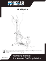
Air Elliptical Pro
IMPORTANT: Read all instructions carefully before using this product.
Retain this owner’s manual for future reference.
The specifications of this product may vary from this photo and, subject to
change without notice.
2307.6-110216

1
TABLE OF CONTENTS
SERVICE ---------------------------------------------------------------------------- 2
LABEL PLACEMENT ------------------------------------------------------------- 3
IMPORTANT SAFETY GUIDELINES ------------------------------------------ 4
OVERVIEW DRAWING ------------------------------------------------------------ 5
PARTS LIST -------------------------------------------------------------------------- 6
HARDWARE & TOOLS PACK --------------------------------------------------- 8
ASSEMBLY --------------------------------------------------------------------------- 10
COMPUTER CONSOLE ---------------------------------------------------------- 22
TENSION ADJUSTMENT --------------------------------------------------------- 23
LEVEL ADJUSTMENTS ----------------------------------------------------------- 24
MOVING THE ELLIPTICAL EQUIPMENT ------------------------------------ 25
MAINTENANCE --------------------------------------------------------------------- 26
TROUBLE SHOOTING ------------------------------------------------------------ 27
WARRANTY -------------------------------------------------------------------------- 29
PARTS REQUEST FORM -------------------------------------------------------- 30

IMPORTANT: FOR NORTH AMERICA ONLY
For damaged or defective product, questions, replacement parts or
any other service support, please contact our customer service
department (8:00 AM - 5:00 PM Pacific Standard Time, Daily) by the
below methods:
For The Best Service, please Email:
Service@paradigmhw.com*
Response Time: 1-2 Business Days
Website:
www.paradigmhw.com**
Toll-Free:
1-844-641-7920
Response time may vary via calling.
Please have the following information ready when requesting for service:
• Your name
• Phone number
• Model number
• Serial number
• Part number
• Proof of Purchase
*Emailing us with the information above will be the best
method to receive a response during peak business hours.
**Response time may vary.
For damaged or defective product please contact our customer
service before returning to the store.
Paradigm Health & Wellness, Inc.
1189 Jellick Ave.
City of Industry, CA 91748, USA
2
LABEL PLACEMENT SERVICE

LABEL PLACEMENT
3

Basic precautions should always be followed, including the following safety
instructions when using this equipment. Read all the instructions before using this
equipment.
1. Before exercising and to avoid injuring your muscles, it is highly recommended that
you perform warm-up exercises for each muscle group.
2. Make sure all the components are not damaged and are in working order before
using. This equipment should be placed on a stable, flat surface. Using a mat or
similar material on the ground is recommended.
3. Please wear proper fitness apparel when using this equipment. Do not wear loose
clothing or accessories that may get caught by any part of the equipment.
4. Only perform maintenance or adjustments that are instructed in this manual. Should
any problems arise, discontinue usage of the equipment and consult with our
customer service.
5. Be careful when stepping on or stepping off the pedals. Always hold onto the
handlebars first and step on the pedals when they are closest to the ground.
6. With your other leg, swing over the main frame and come to rest onto the other
pedal. To ensure the pedals run smoothly, push or pull on the handlebars first before
testing the leg motions. To dismount, reduce pedaling speed gradually before you
stop. When stepping off the machine, make sure you step off one leg at a time. One
leg should be on a pedal at its lowest while the other leg dismounts slowly off the
other pedal. Hold onto the equipment for balance while fully dismounting.
7. Keep dry. Do not operate the equipment in wet or moist condition. Do not use the
equipment outdoors. This equipment is for household use only.
8. Only one person should be on the equipment at a time. Keep children and pets away
from the product at all times. This machine is designed for adults only.
9. This product requires a minimum of 6 feet of space in radius for safe operation.
10. If you feel any chest pains, nausea, dizziness, or short of breath, you should stop
exercising immediately and consult with your physician before continuing.
The maximum weight capacity for this product is 275 lbs/125 kgs.
WARNING: Before beginning any exercise program consult your physician.
This is especially important for the people who are over 35 years old or who have
pre-existing health problems.
CAUTION: Read all instructions carefully before operating this product.
Retain this Owner’s Manual for future reference.
4
IMPORTANT SAFETY GUIDELINES

5
OVERVIEW DRAWING

No.
Description
Qty
No.
Description
Qty
001
Handrail Arm End Cap Ø25
2
023
Bolt M8x43
4
002
Right Handrail Arm
Ø25x1.8x990
1
024 Washer Ø8 8
003
Handrail Arm Foam Grip
Ø24xØ34x280
2
025 Nylon Nut M8 4
004
Handrail Arm Plastic Bushing
Ø32x1.5
2
026 Right Crank 6.7" 1
005
Bolt M10x18
2
027
Spring Washer Ø20xØ13x2
2
006
Spring Washer Ø10xØ18x3
2
028
Nylon Nut for Right Crank 1/2”
1
007
Washer Ø28xØ16xδ5
2
029
Computer Console M1202
1
008
Powder Metal Bushing
Ø24.5xØ16x14
10
030
Hand Pulse Handlebar End Cap
Ø25x1.5
2
009
Right Handrail
1
031
Hand Pulse Sensor
2
010
Extension Sensor Wire
L=650 mm
1
032
Hand Pulse Handlebar Foam Grip
Ø24xØ30x240
2
011
Bolt M10x55
2
033
Hand Pulse Handlebar
1
012
Handrail End Cap Ø32x1.5
2
034
Wire Grommet Ø12.1
2
013
Serrated Lock Washer External
Teeth Ø10
2
035
Hand Pulse Sensor Wire
L=500 mm
2
014
Nylon Nut M10
6
036
Spring Washer Ø8
4
015
Foot Bar End Cap 30x30x1.5
2
037
Tension Control Knob
1
016
Powder Metal Bushing
Ø14xØ10x10
4
038 Bolt M5x15 2
017
Right Foot Bar
1
039
Carriage Bolt M8x35
2
018
Foot Pedal Support Bracket
245x38xδ3.0
2
040 Bottle Holder 1
019L
Left Foot Pedal 349x150x56 1
041
Hand Pulse Handlebar Support
Frame
1
019R
Right Foot Pedal 349x150x56 1
042
Hand Pulse Handlebar Support
Frame End Cap 30x20x2.0
2
020
Bolt M10x45
4
043
Cover Cap Ø25
2
021
Right Bolt for Right Crank
Ø16x89xL23
1
044 Eyebolt M6x33 2
022
Wave Washer Ø28xØ17x0.3
4
045
Nut M10x1xB5
2
6
PARTS LIST

No.
Description
Qty
No.
Description
Qty
046
Tension Bracket
2
074
Nut 7/8"
1
047
Bolt M8x38
8
075
Left Crank 6.7"
1
048
Nut M6
2
076
Left Foot Bar
1
049
Fan Wheel Ø503x85
1
077
Left Handrail
1
050
Fan Wheel Axle
M10x1xL150xL25xL40
1
078 Sensor with Wire L=900 mm 1
051
Spacer Ø16xØ10x20
1
079
Tension Cable L=1020 mm
1
052
Bolt M10x57
4
080
Cap Nut M8
6
053
Front Stabilizer End Cap Ø50
2
081
Big Curve Washer Ø8xØ20x2
6
054
Front Stabilizer Ø50x1.5
1
082
Flange Nut M10x1xB10
2
055
Curve Washer Ø10xØ25x2
4
083
Right Cover 705x362
1
056
Cap Nut M10
4
084
Left Cover 705x362
1
057
Adjustable Leveler M8x45
2
085
Chain
1
058
Nut M8
2
086
Screw ST4.2x20
2
059
Mainframe
1
087
Nylon Nut for Left Crank 1/2”
1
060
Rotation Rod Ø15.8x376
1
088
Nut Cap S16
4
061
Rear Stabilizer End Cap Ø50
2
089
Small Magnet Ø15x7
1
062
Rear Stabilizer Ø50x1.5x540
1
090
Left Handrail Arm Ø25x1.8x990
1
063
Tension Strap 1150x18
1
091
Crank Cover Ø22
2
064
Left Bolt for Left Crank
Ø16x89xL23
1
092 Bolt M6x45 2
065
Screw ST4.8x40
7
093
Transport Wheel Ø23xØ6x32
2
066
S Phillips Self Drilling Screw
ST4.8x20
3
094 Nylon Nut M6 2
067
Chain Pulley
1
095
Plastic Clip 20
1
068
Washer Ø40x24x3
1
096
Flange Nut M10x1.25
2
069
Bearing Nut II 15/16"
1
097
Nut Cap S18
2
070
Bearing
2
098
Spring Ø12x1.8x32
1
071
Bearing Cup
2
099
Round Plug Ø25x1.5
4
072 Bearing Nut I 7/8" 1
100
Cross Recessed Pan Head Screw
M5x15
1
073
Washer Ø34.5x23x2.5
1
101
Clip
1
7
PARTS LIST

HARDWARE & TOOLS PACK
8

THIS PAGE IS INTENTIONALLY LEFT BLANK
9

1. Front/Rear Stabilizers and Adjustable Levelers Installation:
Align the holes of the Front Stabilizer (54) to the bracket located at the front end of the Mainframe
(59). Make sure the arrow sticker on the Front Stabilizer (54) is pointing up so that the Transport
Wheels (93) are positioned toward the front and parallel to the floor. Insert two Bolts (52) through
the Front Stabilizer (54) and secure with two Curve Washers (55) and two Cap Nuts (56). Using
the Open-Ended Flat Wrench, tighten the Cap Nuts (56) until they are secure.
Align and attach the Rear Stabilizer (62) to the bracket located at the bottom of the back end of
Mainframe (59) with two Bolts (52). Secure the two Bolts (52) with two Curve Washers (55) and
two Cap Nuts (56). Using the Open-Ended Flat Wrench, tighten the Cap Nuts (56) until they are
secure.
Hardware:
Tools:
Open-Ended Flat Wrench
(52) Bolt M10x57
4PCS
(55) Curve Washer
Ø10xØ25x2
4PCS
(56) Cap Nut M10
4PCS
10
ASSEMBLY
10

2. Handrails, Foot Bars and Rotation Rod Installation:
Position the Right Foot Bar (17) so that it angles downwards as shown above. Attach the Right
Foot Bar (17) onto the brackets on the bottom end of the Right Handrail (9) with one Bolt (11) and
one Nylon Nut (14). Tighten the bolt until it is firm against the bracket on the Right Handrail (9).
Cover the Bolt (11) and Nylon Nut (14) with two Nut Caps (88).
Using the provided 6mm Allen Wrench, remove the PRE-ASSEMBLED bolts and washers from
both sides of the Rotation Rod (60) and put them to the side. Take the Rotation Rod (60) and
lubricate it with the Grease provided.
Insert the Rotation Rod (60) into the tube on the top of the Mainframe (59) (above the flywheel).
Slide the Right Handrail (9) onto the right end of the Rotation Rod (60) and insert a Bolt (5),
Spring Washer (6), Washer (7), and Waves Washer (22) on to the right end of the Rotation Rod
(60). Do not tighten the Bolt (5) until both handrails have been mounted to the Rotation Rod (60).
Repeat the steps above for installing the Left side parts (75), and (77) onto the Rotation Rod (60).
Use both the 6mm Allen Wrench and the 6mm Allen Wrench with a Phillips Screwdriver to
secure the Bolts (5) on both ends of the Rotation Rod (60). Tighten the both Bolts (5) at the same
time until firm and secure.
Hardware:
(11) Bolt M10x55
2PCS
(14) Nylon Nut M10
2PCS
(88) Nut Cap S16
4PCS
11
Tools:
6mm Allen Wrench & 6mm Allen Wrench
with Phillips Screwdriver
ASSEMBLY

.
3. Foot Pedal Support Bracket and Right Crank Bolt Installation:
Attach the Foot Pedal Support Bracket (18) onto the right side of the Right Foot Bar (17) using
two Bolts (23), two Washers (24), and two Nylon Nuts (25). Use the Open-Ended Flat Wrench
and 6mm Allen Wrench to tighten the Foot Pedal Support Bracket (18) to the Right Foot Bar
(17).
Lubricate the Right Crank Bolt (21) with some of the Grease provided. Insert the Right Crank
Bolt (21) and one Wave Washer (22) through the right holes of the Right Foot Bar (17). Raise the
rear end of the Right Foot Bar (17) and align it with the threaded hold of the Right Crank (26).
Make sure the Right Crank Bolt (21) is perfectly level and straight as you insert it through the hole
of the Right Crank (26). Turn the Right Crank Bolt (21) clockwise by hand until it is firm. After
hand tightening, completely tighten the Right Crank Bolt (21) with the 8mm Allen Wrench
provided. Put one Spring Washer (27) and one Right Nylon Nut (28) on to the threaded end of the
Right Crank Bolt (21). Use the Open-Ended Wrench on the Right Nylon Nut (28) and the 8mm
Allen Wrench on the Right Crank Bolt (21) simultaneously to tighten the Right Nylon Nut (28).
Cover the Right Nylon Nut (28) with one Cap (97).
Read the note on next page regarding tightening guidelines. Refer to the illustration
showing the correct installation of the Right Crank Bolt (21). See Figure F on the next page.
12
ASSEMBLY
Tools:
6mm Allen
Wrench
Open-Ended
Flat Wrench
8mm Allen
Wrench
Important:
Installing right bolt into right
crank can only be done by
turning right (CLOCKWISE).
R for right bolt

Hardware
Figure F.
Note: Figure F shows the correct installation of the Right Crank Bolt
(21). Keep the bolt perfectly straight when the bolt goes through the
Right Foot Bar (17), and is being screwed into the Right Crank (26). If
the bolt is screwed into the crank at an angle, this may damage the
equipment.
Please make sure the right bolt is for the right crank only and the
left bolt is for the left crank only. If done incorrectly, the bolts
and/or cranks may be damaged or stripped.
(21) Right Crank Bolt
1PC
(22) Wave Washer
Ø28xØ17x0.3
1PC
(23) Bolt M8x43
2PCS
(24) Washer Ø8
2PCS
(25) Nylon Nut M8
2PCS
(27) Spring Washer
Ø20xØ13x2
1PC
(28) Right Nylon Nut
1PC
(97) Nut Cap S18
1PC
ASSEMBLY
13

4. Foot Pedal Support Bracket and Left Crank Bolt Installation:
Attach the Foot Pedal Support Bracket (18) onto the left side of the Left Foot Bar (76) using two
Bolts (23), two Washers (24), and two Nylon Nuts (25). Use the Open-Ended Flat Wrench and
6mm Allen Wrench to tighten the Foot Pedal Support Bracket (18) to the Left Foot Bar (76).
Lubricate the Left Crank Bolt (64) with some of the grease provided. Insert the Left Crank Bolt
(64) and one Wave Washer (22) through the left holes of the Left Foot Bar (76). Raise the rear
end of the Left Foot Bar (76) and align it with the threaded hold of the Left Crank (75).
Make sure the Left Crank Bolt (64) is level and straight as you insert it through the threaded hole
of the Left Crank (75). Turn the Left Crank Bolt (64) counter-clockwise by hand until it is
firm. After hand tightening, completely tighten the Left Crank Bolt (64) with the 8mm Allen
Wrench provided. Put one Spring Washer (27) and one Left Nylon Nut (87) on to the threaded
end of the Left Crank Bolt (64). Use the Open-Ended Wrench on the Left Nylon Nut (87) and the
8mm Allen Wrench on the Left Crank Bolt (64) simultaneously to tighten the Left Nylon Nut
(87).
Cover the Left Nylon Nut (87) with one Cap (97).
Read the note on next page regarding tightening guidelines. Refer to the illustration
showing the correct installation of the Left Crank Bolt (64). See Figure F on the next page.
14
L for left bolt
Important:
Installing left bolt into left
crank can only be done
by turning left
(COUNTER-CLOCKWISE).
Tools:
6mm Allen Wrench
Open-Ended Flat Wrench
8mm Allen Wrench
ASSEMBLY

Hardware:
ASSEMBLY
(64) Left Crank Bolt
1PC
(22) Wave Washer
Ø28xØ17x0.3
1PC
(23) Bolt M8x43
2PCS
(24) Washer Ø8
2PCS
(25) Nylon Nut M8
2PCS
(27) Spring Washer
Ø20xØ13x2
1PC
(87) Left Nylon Nut
1PC
(97) Nut Cap S18
1PC
15
Figure F.
Note: Figure F shows the correct installation of the Left Crank Bolt
(64). Keep the bolt perfectly straight when the bolt goes through the Left
Foot Bar (76), and is being screwed into the Left Crank (75). If the bolt
is screwed into the crank at an angle, this may damage the equipment.
Please make sure the right bolt is for the right crank only and the
left bolt is for the left crank only. If secured incorrectly, the bolts
and/or cranks may be damaged or stripped.

5. Right and Left Foot Pedals Installation:
Attach the Right Foot Pedal (19R) onto the top of the right side Foot Pedal Support Bracket (18)
located on the Right Foot Bar (17) with two Bolts (20) and two Nylon Nuts (14). Tighten the
Nylon Nuts (14) using the Open-Ended Flat Wrench provided.
Attach the Left Foot Pedal (19L) onto the top of the left side Foot Pedal Support Bracket (18)
located on the Left Foot Bar (76) with two Bolts (20) and two Nylon Nuts (14). Tighten the Nylon
Nuts (14) using the Open-Ended Flat Wrench provided.
Hardware:
(20) Bolt M10x45
4PCS
(14) Nylon Nut M10
4PCS
16
ASSEMBLY
Tools:
Open-Ended Flat Wrench

6. Right and Left Handrail Arms Installation:
Insert the Right Handrail Arm (2) with the handlebar grip bent outwards into the Right Lower
Handrail (9) and align the holes. Secure the Right Handrail Arm (2) using two Big Curve
Washers (81), two Bolts (47), and two Cap Nuts (80). Tighten the nuts and bolts using the 6mm
Allen Wrench and Open-Ended Flat Wrench simultaneously.
Insert the Left Handrail Arm (90) with the handlebar grip facing outwards into the Left Lower
Handrail (77) and align the holes. Secure the Left Handrail Arm (90) using two Big Curve
Washers (81), two Bolts (47), and two Cap Nuts (80). Tighten the nuts and bolts using the 6mm
Allen Wrench and Open-Ended Flat Wrench simultaneously.
17
ASSEMBLY
Tools:
6mm Allen Wrench
Open-Ended Flat Wrench
(47) Bolt M8x38
4PCS
(81) Big Curve Washer
Ø8xØ20x2
4PCS
(80) Cap Nut M8
4PCS
Hardware:

7. Support Frame Handlebar Installation:
As you begin to mount the Hand Pulse Handlebar Support Frame (41) to the Mainframe (59),
insert the Tension Cable (79) through the bottom opening in the shaft of the Hand Pulse
Handlebar Support Frame (41) and pull it out through the shaft opening located midway up the
support frame. See Figure G.
Fully mount the Hand Pulse Handlebar Support Frame (41) to the Mainframe (59). After being
mounted, secure the Hand Pulse Handlebar Support Frame (41) onto the Mainframe (59) with
four Bolts (47), four Spring Washers (36), and four Washers (24). Use the 6mm Allen Wrench
with Phillips Screwdriver to tighten the bolts until they are firm and secure.
Connect the Sensor Wire (78) attached to the Mainframe (59) to the Extension Sensor Wire (10)
coming from the bottom end of the Hand Pulse Handlebar Support Frame (41). Make sure the
connectors “click” when connected. See Figure A.
Multi Hex Tool with Phillips
Screwdriver
Tools:
6mm Allen Wrench with
Phillips Screwdriver
ASSEMBLY
18
Figure G
Figure A
(47) Bolt M8x38
4PCS
(24) Washer Ø8
4PCS
(36) Spring Washer Ø8
4PCS
Hardware:
/


