Page is loading ...

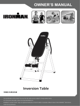
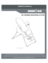
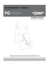
OWNER’S MANUAL
Infrared Inversion Table
5214.5-082517
The specifications of this product may vary from this photo and are subject to change without notice.
For more brand information, please visit www.IRONMAN.com
IRONMAN® and the "M-DOT" logo are registered trademarks of World Triathlon Corporation Official Product of the IRONMAN® TRIATHLON.
Used here by permission.

PLEASE DO NOT RETURN THIS PRODUCT T
O THE STORE.
STOP and contact customer service if you have any questions
regarding assembly or proper operation of the machine.
Email us at:
Service@paradigmhw.com
Or call us at:
1-844-641-7922
Hours:
8:00 am to 5:00 pm (PST) Daily
Email us at:
Service@paradigmhw.com
STOP
ARRÊT
ALTO

SERV
I
LABE
L
IMPO
R
OVE
R
PART
HARD
A
SSE
M
SAFE
T
OPE
R
STOR
A
TEMP
TOUB
WAR
R
PART
S
I
CE -------
L
PLACE
M
R
TANT S
A
R
VIEW D
R
LIST -----
-
WARE LI
M
BLY ----
-
T
Y OPE
R
R
ATION &
A
GE & M
A
ERATUR
E
LESHOO
R
ANTY ---
S
REQU
E
T
A
------------
-
M
ENT ----
A
FETY G
U
R
AWING -
-
-----------
-
ST & TO
O
-
-----------
-
R
ATING I
N
A
DJUST
M
A
INTEN
A
E
& REM
O
TING-----
-
------------
-
E
ST FOR
M
A
BLE
O
-
-----------
-
-
-----------
-
U
IDELIN
E
-
-----------
-
-
------------
-
O
LS PAC
K
-
------------
N
STRUC
T
M
ENTS -
-
A
NCE ----
-
O
TE CO
N
-
-----------
-
-
------------
M
----------
-
1
O
F CO
-
------------
-
-
-----------
-
E
S --------
-
-
-----------
-
------------
-
K
-----------
------------
-
T
IONS ----
-
------------
-
-
------------
-
N
TROLLE
-
------------
-
-
------------
-
-
-----------
-
NTEN
T
-
-----------
-
-
------------
-
-
-----------
-
------------
-
-
-----------
-
------------
-
-
-----------
-
------------
-
-
-----------
-
-
-----------
-
R ---------
-
-
-----------
-
-
-----------
-
-
------------
T
S
-
------------
-
-
-----------
-
------------
-
-
-----------
-
------------
-
-
------------
-
------------
-
-
------------
-
------------
-
------------
-
-----------
-
-
------------
-
-
------------
-
-
-----------
-
------- 2
-
------- 3
-
------- 4
-
------- 7
-
------ 8
-
------- 1
0
-
------- 1
1
-
------- 1
7
-
------- 2
0
-
------- 2
5
-
------- 2
6
------- 2
7
------- 2
8
-
------ 2
9
0
1
7
0
5
6
7
8
9

IM
Fo
r
su
p
F
o
s
e
Re
s
E
m
pe
a
W
e
w
w
Tol
1-8
4
(8:
Re
s
Ple
Fo
r
the
Pa
r
11
8
Cit
y
PORT
A
r
damage
d
p
port, ple
a
o
r The
e
rvice
@
s
ponse Ti
m
ailing us
w
a
k busine
s
e
bsite
:
w
w.pa
r
l-Free:
4
4-641-79
0
0 AM -
5
s
ponse ti
m
ase have
Your na
m
Phone n
Model n
u
Serial n
u
Part nu
m
Proof of
r
damage
d
store.
r
adigm H
e
8
9 Jellick
A
y
of Indu
s
A
NT: FO
d
or defec
a
se conta
c
Best
S
@
para
d
me: 1-2 B
w
ith the i
n
s
s hours
:
r
adig
m
22
5
:00 PM
m
e may v
a
the follo
w
m
e
umber
u
mber
u
mber
m
ber
Purchas
e
d
or defec
e
alth & W
e
A
ve.
s
try, CA 9
1
R NOR
T
tive prod
u
c
t our cu
s
S
ervice
d
igmh
w
usiness
D
n
formatio
n
m
hw.co
m
Pacific
S
a
ry via ca
l
w
ing infor
m
e
tive prod
u
e
llness, In
1
748, US
A
S
T
H AM
E
u
ct, quest
s
tomer se
r
, plea
s
w
.com
D
ays
n
above
w
m
S
tandar
d
l
ling
m
ation re
a
u
ct pleas
e
c.
A
2
S
ERVI
C
E
RICA
O
t
ions, repl
r
vice dep
a
s
e Em
a
w
ill be the
d
Time,
D
a
dy when
e
contact
o
C
E
O
NLY
acement
p
a
rtment b
y
a
il:
best met
h
D
aily)
requesti
n
o
ur custo
m
p
arts or a
n
y
the belo
h
od to rec
e
n
g for ser
v
m
er servi
c
n
y other
s
o
w metho
d
e
ive a res
v
ice:
c
e before
s
ervice
d
s:
ponse du
r
returning
r
ing
to

W
ARNING
AVERTISSEMENT
T
o avoid serious injury,
hold on to handle bars
and invert slowly
Pour éviter des blessures
graves, bien tenir les poignées
de sécurité et procéder à
and
invert
slowly
.
de
sécurité
et
procéder
à
l'inversion lentement.
L
A
For customer assistance call:
Pour le service a la clientèle
composer le:
A
BEL
1-844-641-7922
8 am - 5 pm PST
Daily
composer
le:
1-844-641-7922
Tous les jours
8:00 h - 17 h (HNP)
3
PLAC
E
E
MEN
T
13
13
13
13
T
S
Heel Bracket must
WARNING AVERTISSEMENT
AVERTISSEMENT
Le poids maximum pout ce produit
est 159 k
g
s.
Maximum weight capacity is 350 lbs.
Heel
Bracket
must
be secured in slot
before use.
Support de talon
doit être xé dans
la fente avant
g
la
fente
,
avant
utilization.

Re
a
pr
e
W
A
1.
2.
3.
pe
o
4.
5.
6.
da
m
7.
8.
9.
10.
rec
o
11.
12.
13.
14.
15.
dis
a
16.
co
m
17.
im
m
18.
the
19.
rep
r
20.
equ
Do
21.
22.
23.
of
a
24.
inv
e
25.
and
26.
Inst
a
d all inst
e
cautions
A
RNING -
T
Make sure
Be sure all
The equip
m
o
ple.
Before usi
n
Only one p
e
Never ope
r
m
aged. If a
p
A
lways us
e
For house
h
Do not us
e
Use the in
v
o
mmended
A
lways we
a
Do not we
a
Keep all h
a
Never dro
p
Close sup
e
a
bled perso
Listen to y
o
m
e up too f
a
If at any ti
m
m
ediately. Y
o
Wait at lea
s
upright po
s
For any pr
o
r
esentative
.
Warni
n
ipment is
a
not use thi
s
Warni
n
Warni
n
Warni
n
a
ll moving
p
Warni
n
e
rting. Failu
Warni
n
contact cu
Warni
n
ructions B
e
I
M
ructions
b
should al
w
T
o reduce
your equip
m
screws, nu
m
ent weigh
s
n
g this equi
p
erson shou
r
ate this E
p
roblem is
e
e
this equip
m
h
old use on
l
e
outdoor
s
v
ersion tabl
e
by the ma
n
a
r shoes w
h
a
r loose clo
t
a
nds and fe
e
p
or insert a
n
e
rvision is n
ns.
o
ur body. It
a
st.
m
e you fe
e
o
u should
a
s
t 2 hours
a
s
ition slowl
y
o
blems co
n
.
Our conta
c
n
g:
- Ris
a
ppropriate
s
equipmen
t
n
g:
-
Ris
k
n
g:
-
Ris
k
n
g:
-
Ris
k
parts.
n
g:
- Ris
k
re to compl
n
g:
- Ris
stomer ser
v
n
g
:
- To
e
fore Using
M
POR
T
b
efore usi
w
ays be f
o
the risk
o
m
ent is cor
r
ts, and bol
t
s
more tha
n
p
ment, we
r
ld be using
quipment i
f
e
ncountere
m
ent on a
c
l
y.
s
or near
w
e
only for it
s
n
ufacturer.
h
en using t
h
t
hing when
e
t away fro
m
n
y object i
n
ecessary
w
is recomm
e
e
l faint, ligh
t
a
lso stop e
x
a
fter eating
y
.
n
tact custo
m
c
t number i
s
k of Perso
for you. Th
t
without y
o
k
of Person
a
k
of Person
a
k
of Person
a
k
of Person
a
y could res
k of Perso
n
v
ice.
Reduce
T
The Invers
i
T
ANT
S
ng the In
v
o
llowed, i
o
f injury t
o
r
ectly asse
m
t
s are tight
e
n
44lbs / 2
0
r
ecommen
d
the equip
m
f
it is dam
a
d contact
C
c
lear and le
v
w
ater.
s
intended
u
h
e inversio
n
using the
e
m
any mov
i
n
to any ope
n
w
hen the in
v
e
nded that
y
t
-headed,
o
x
ercising if
y
before usi
n
m
er servic
e
s
on the se
nal Injury
-
is is espec
o
ur physicia
a
l Injury –
D
a
l Injury - K
a
l Injury
–
K
a
l Injury -
A
l
w
ult in serio
u
n
al Injury -
T
he Risk
O
i
on Table.
4
S
AFET
Y
v
ersion T
a
ncluding
t
o
persons
m
bled befo
r
e
ned prior t
o
0
kgs and s
d
doing wa
r
m
ent at a ti
m
a
ged, if it
C
ustomer S
e
vel surface
u
se as des
c
n
table.
e
quipment.
ing parts.
n
ing.
v
ersion tabl
y
ou rotate
u
o
r dizzines
s
y
ou are exp
n
g the inver
s
e
. Servicin
g
rvice page.
-
Consult
w
ially import
a
n's approv
a
D
o not allo
w
K
eep childre
K
eep bod
y
w
ays hold
o
u
s bodily inj
Do not att
e
O
f Personal
Y
GUI
D
a
ble. Whe
n
t
he follo
w
:
r
e you use
i
o
use.
hould be a
s
r
m ups.
m
e.
is not wor
k
e
rvice befo
r
.
c
ribed in thi
s
e is used n
u
p and do
w
s
while ope
r
eriencing p
s
ion table.
I
g
should b
e
w
ith your p
e
a
nt for peo
p
a
l.
w
children t
o
n under th
e
y
parts, ha
i
o
n to the sa
ury.
e
mpt to ser
v
Injury -
R
D
ELIN
E
n
using a
n
w
ing:
t.
s
sembled
a
k
ing prope
r
r
e using th
e
s
manual.
D
e
ar childre
n
w
n slowly. D
r
ating the
e
ain or any
d
f you start
f
e
performe
d
e
rsonal ph
y
p
le with pr
e
o
use this
m
e
age of 13
r, loose cl
o
fety handle
v
ice the uni
t
R
ead And
U
E
S
n
Inversio
a
nd moved
r
ly, has be
e
e
equipmen
D
o not use
a
n
, or by or
n
izziness mi
e
quipment,
d
iscomfort.
f
eeling nau
s
d
by an au
t
y
sician to
s
e
-existing h
m
achine.
away from
o
thing, an
d
s and tilt-b
a
t
yourself.
D
U
nderstan
d
n table, b
a
by two or
m
e
n droppe
d
t
again.
a
ttachment
s
n
ear invalid
ght occur i
f
stop exerc
i
s
eous, retu
t
horized se
r
s
ee if inve
r
ealth probl
e
the machin
d
jewelry
c
a
ck slowly
w
D
iscontinu
e
All Read
a
sic
m
ore
d
, or
s
not
s, or
f
you
i
sing
rn to
r
vice
r
sion
e
ms.
e.
c
lear
w
hen
e
use
The

Do
ort
h
D
o
u
s
Th
e
Th
e
R
e
fo
r
not use t
h
Pregnanc
y
Extreme
o
Middle ea
Hiatus he
r
Glaucom
a
Use of an
t
Spinal inj
u
Heart or
c
High bloo
d
Bone we
a
h
opedic su
p
o
not e
x
er heig
h
e
Maximu
m
e
Maximu
m
e
tain th
r
future
I
M
h
is equip
m
y
o
besity
r infection
r
nia or Ven
t
a
, retinal de
t
icoagulant
s
u
ry, Cerebr
a
c
irculatory
d
d
pressure,
a
knesses i
n
p
ports.
x
ceed t
h
h
t:
m
Weight
m
Rated
H
is own
e
refere
n
M
POR
T
The prod
recomm
e
m
ent if yo
t
ral hernia
tachment
o
s
including
A
a
l Sclerosis
d
isorders fo
r
Hypertens
n
cluding O
s
h
e max
i
Capacity
H
eight thi
s
e
r’s m
a
n
ce.
S
A
T
ANT
S
uct weig
h
e
nded tha
t
u have a
n
o
r conjuncti
v
A
spirin in h
, or acutely
r
which you
ion, Recen
t
s
teoporosis
,
i
mum r
a
for this p
r
s
product
a
nual a
n
A
VE TH
E
5
S
AFET
Y
h
s more t
h
t
at least
2
n
y of the f
o
v
itis
igh doses.
y
swollen joi
are being
t
t
stroke or
T
,
Unhealed
a
ted w
e
r
oduct is
3
is 6’6”/19
n
d kee
p
E
SE GU
Y
GUI
D
h
an 44 lbs
2
Persons
o
llowing
c
nts
t
reated
T
ransient Is
fractures,
e
ight (l
o
3
50lbs/15
9
8cm.
p
the o
r
IDELIN
E
D
ELIN
E
. It is hea
v
assembl
e
c
ondition
s
c
hemic att
a
Modular pi
n
o
ad) an
d
9
kgs.
r
iginal
p
E
S
E
S
v
ily
e
.
s
or ailme
n
a
ck
n
s, or surg
d
maxi
m
purcha
s
n
ts:
i
cally impla
m
um ra
t
s
e rec
e
nted
t
ed
e
ipt

EL
Wh
the
Re
a
DA
per
1.
2.
3.
4.
5.
6.
7.
8.
9.
10.
11.
ECTRIC
A
en using t
h
following:
a
d all instr
u
NGER - T
o
s
ons:
The far i
n
outlet wh
Excessiv
Close su
p
disabled
Use this
u
purpose
t
STOP u
s
properly,
Keep the
Do not u
s
Do not o
p
administ
e
To disco
n
plug fro
m
Do not u
s
CABLE
S
frame as
THE DI
M
There is
a
( width) ,
as below
I
M
A
L SAF
E
h
e far infr
a
u
ctions be
f
o
reduce t
h
n
frared fo
a
en not in
u
e heating
m
p
ervision i
s
persons.
u
nit only f
o
t
hat is not
s
ing this u
n
been dro
p
e
cord awa
y
s
e it outdo
o
p
erate wh
e
e
red.
n
nect, turn
m
outlet.
s
e on an i
n
S
TORAG
E
illustrated
M
ENSION
O
a
heating
p
o
r
700m
m
:
M
POR
T
E
TY
a
red foam
b
f
ore using
h
e risk of
e
a
m bed sh
o
u
se and b
e
m
ay occu
r
s
necessa
o
r its inten
d
recomme
n
n
it IMMEDI
p
ped, dam
a
y
from an
y
o
rs.
er
e aeroso
the remot
n
fant or on
E
: When n
o
. Do not l
a
O
F HEATI
N
p
ad inside
m
(length)
x
Heating
T
ANT
S
b
ed, basic
this unit.
e
lectric sh
o
o
uld never
e
fore clean
r
and caus
e
ry when t
h
d
ed use a
s
n
ded by th
e
ATELY if i
t
a
ged, or d
r
y
heated s
u
l (spray) p
e control
o
a sleepin
g
o
t in use,
w
a
y it on the
N
G PAD:
the foam
b
x
300mm (
w
Pad
6
S
AFET
Y
c
precautio
n
o
ck, of bur
n
be left un
a
n
ing.
e
fire, ele
c
h
is unit is
u
s
describe
d
e manufa
c
t
has a da
m
r
opped int
o
u
rface.
roducts ar
o
r controll
e
g
person.
w
ind the c
a
ground to
b
ed. The
h
w
idth) in d
3
0
Y
GUI
D
n
s should
n
s, fire, el
e
a
ttended
w
c
tric shock,
u
sed by, o
n
d
in this m
a
c
turer.
m
aged co
r
o
water.
e being u
s
e
r to the “
O
a
ble aroun
d
avoid ca
b
h
eating pa
d
imension.
00
D
ELIN
E
a
lways be
e
ctric shoc
k
w
hen plug
g
or injury t
o
n
, or near
c
a
nual. Do
d or plug.
s
ed or whe
O
FF” positi
o
d
the anch
le damag
e
d
is 27.55”
The heati
n
700
100
E
S
followed,
k, or injur
y
g
ed in. Un
p
o persons
.
c
hildren, in
not use fo
If it is not
w
re oxygen
o
n, then r
e
h
ors on th
e
e
.
(length) x
n
g area is
including
y
to
p
lug from
.
valids or
r
other
w
orking
is being
e
move
rear right
11.81”
i
llustrated

O
O
VERV
I
7
I
EW D
R
R
AWI
N
G

No.
1
2
3
4
5
6
7
8
9
10
11
12
13
14
15
16
17
18
19
20
21
22L
22R
23
24
25
26
27
Front Fr
a
Rear U-
F
A
djustab
l
Bed Fra
m
Pivot Ar
m
A
djustab
l
Heel Hol
d
Folding
A
Rear Ro
d
Bolt M8x
2
Front Ro
d
Phillips
S
Washer
Ø
Round P
l
Lock Nut
Lock Nut
Blocking
Spring K
n
Safety H
o
Rubber
P
Rear U-
F
Left Adju
s
Right Adj
In-Step
F
In-Step
F
Round E
n
Lower B
e
Washer
Ø
Descri
p
a
me
F
rame
l
e Boom
m
e
m
l
e Lock Pl
a
d
er Brack
e
A
rm
d
2
3
d
S
crew M6x
3
Ø
20xØ8.5
x
l
ate
M8
M6
Bush Ø2
8
n
ob
o
ok
P
ad
F
rame Ov
a
s
table Bo
o
ustable B
o
F
rame
F
oot Pad
n
d Cap
e
d Frame
B
Ø
16xØ6.5
x
p
tion
a
te
e
t
3
5
x
1.5
8
.5xØ23x1
4
a
l End Cap
o
m Plate
o
om Plate
B
ushing
x
1.0
P
A
Q
t
1
1
1
1
2
1
4
2
1
2
1
4
1
7
1
1
2
6
4
2
1
2
1
2
1
1
2
2
4
1s
e
6
8
A
RTS L
t
y
2
2
3
3
2
3
3
4
3
2
3
3
2
3
3
4
3
7
4
4
2
4
6
4
2
4
4
2
4
4
2
4
4
4
2
5
2
5
4
5
e
t
5
6
5
IST
No.
2
8 Up
p
2
9 Ha
n
3
0 Kn
o
3
1 Ru
b
3
2 Nyl
o
3
3 Lo
o
3
4 Str
a
3
5 Fo
a
3
6 Far
3
7 Pro
t
3
8 He
x
3
9 Fro
n
4
0L Lef
t
4
0R Rig
h
4
1
A
dj
u
Ca
p
4
2 Loc
4
3 He
x
4
4 Hei
g
4
5 Lat
c
4
6 He
x
4
7 Lef
t
4
8 Lef
t
4
9 Rig
h
5
0 Rig
h
5
1 Bol
t
5
2
Be
d
(□2
5
5
3 Fro
n
5
4 Scr
e
De
s
p
er Bed Fr
a
n
dleba
r
o
b
b
ber Heel
H
o
n Strap
p Strap
a
p Lock
a
m Bed
Infrared F
t
ective Co
v
x
Head Bol
n
t Plastic
C
t
Plastic C
o
h
t Plastic
C
u
stable B
o
p
king Pin
x
Head Bol
g
ht Scale
c
h
x
Head Bol
t
Rear Foo
t
t
Front Fo
o
h
t Rear F
o
h
t Front F
o
t
M6x25
d
Frame E
n
5
x50mm)
n
t Foot Ca
e
w ST3.5
x
s
cription
a
me Bush
H
olde
r
oam Grip
v
e
r
l
t M8x23
C
ove
r
o
ve
r
C
ove
r
o
om Squar
e
l
t M8x43
l
t M8x40
o
t Cap with
o
t Cap wit
h
o
ot Cap wi
t
o
ot Cap wi
n
d Cap
a
p
x
15
ing
e
End
Handle
h
Handle
t
h Handle
th Handle
Qty
1
2
1
4
1
1
1
1
2
2
2
1
1
1
2
1
2
1
1
5
1
1
1
1
2
5
2
10

No.
55
56
57
58
59
60
61
62
63
64
65
66
67
Nut Cap
Ø
A
djustabl
e
Handle C
a
Handle S
p
Button
Handle Ti
p
Blocking
B
Screw M
3
Bolt M6x1
Carriage
B
Bolt M6x
3
Spacer Ø
2
Screw S
T
Descrip
Ø
27xØ13.
5
e
Handle
a
p
p
ring
p
B
ush Ø28.
3
x10
5
B
olt M8x7
0
3
0
2
2x16.8
T
4.2x12
tion
5
5xØ22.5x
1
0
P
A
Qt
y
4
1
1
1
1
1
1
0 2
10
1
2
1
2
8
9
A
RTS L
y
N
6
8
6
9
7
0
71
7
2
7
3
7
6
7
7
7
8
7
9
8
0
81
IST
N
o.
8
Scre
w
9
Shaft
0
Bolt
M
Bolt
M
2
Pivot
A
3
Bolt
M
6
Powe
7
Rem
o
8
Velcr
o
9
A
nch
o
0
Scre
w
Tem p
e
De
s
w
ST4.8x2
0
Nut Ø8
M
5x10
M
8x50
A
rm Ring
M
4x16
r Cord
o
te Control
o
Strap
or
w
ST4.0x1
6
e
rature C
o
s
cription
0
6
o
ntrol Box
Qty
1
1
2
4
2
1
1
1
2
2
2
1

HARDWAR
10
R
E & T
O
O
OLS
P
P
ACK

St
e
1A
Sta
U-
F
the
1B
A
tt
a
tw
o
Ca
p
Ri
g
the
ca
p
Ha
M
P
T
o
e
p 1
Setting U
nd up the
F
rames (1
,
two Foldi
n
Securing
a
ch both t
h
o
Bolts (51
p
With Ha
n
g
ht Rear F
back righ
t
p
s with ha
n
rdware:
M
ulti Hex
T
P
hillips Sc
1
P
o
ol:
(51)
B
2 P
C
p The Fra
base of th
e
,
2) as far
a
ng Arms
(
The Foot
h
e Front F
). Wrap b
o
n
dle (48)
o
oot Cap
W
t
corner of
n
dles. Atta
c
T
ool with
rewdrive
r
P
C
B
olt
C
S
mes
e
machine
a
part from
(
8) until th
e
Caps Fo
r
oot Caps
o
th the Le
f
o
utside th
e
W
ith Hand
the Rear
U
c
h all the f
o
r
4
AS
by separ
a
each oth
e
e
y are full
y
r
The Fra
m
(53) onto
t
f
t Rear Fo
o
e
back left
le (49) an
d
U
-Frame (
2
o
ot caps a
2
9
50
4
(27)
W
4
P
11
S
SEM
B
a
ting the fr
a
e
r as possi
b
y
straight a
m
es
t
he Front
o
t Cap Wi
corner of
t
d
Right Fr
2
). Use ei
g
s shown a
1
54
7
5
W
asher
P
CS
B
L
Y
a
mes. Pul
l
b
le. Then
p
nd locked.
F
rame (1)
th Handl
e
t
he Rear
U
ont Foot
C
g
ht Screw
s
bove.
8
48
53
51
l
the Fron
t
p
ush dow
n
with two
W
e
(47) and
t
U
-Frame (
2
C
ap With
H
s
(54) to ti
g
54
27
(54)
S
8P
t
and Rea
r
n
on the m
W
ashers (
2
t
he Left F
r
2
). Wrap b
o
H
andle (5
0
g
hten the
r
53
51
27
S
crew
P
CS
r
i
ddle of
2
7) and
r
ont Foot
o
th the
0
) outside
r
ear foot

St
e
2A
A
tt
a
Nu
t
2B
Sli
d
of t
h
are
Vel
c
se
c
Ha
St
e
3A
En
s
sid
e
e
p 2
Installing
a
ch one N
u
t
s (15).
Installing
d
e the Pro
t
h
e frame.
covering
t
c
ro straps
c
ure the co
rdware:
e
p 3
Installing
s
uring that
e
s of the
B
(
5
4
5
Nut Cap
s
u
t Cap (5
5
the Prot
e
t
ective C
o
Pull down
t
he Foldin
on the bo
t
o
vers to th
e
a
the Pivot
both Piv
o
B
ed Fram
e
5
5) Nut C
a
2 PCS
4
s
Onto Th
e
5
) onto ea
c
e
ctive Co
v
o
vers (37)
on the co
v
g Arms (
8
t
tom of the
e
folding a
r
Arms
o
t Arms (5
)
e
(4), secu
r
a
p
AS
e
Joint Fr
a
c
h of the L
o
v
ers
onto both
s
v
ers until t
h
8
). Use the
covers to
r
ms.
)
are align
e
r
e the arm
s
5
12
S
SEM
B
a
mes
o
ck
s
ides
h
ey
e
d at the
s
s
into the
p
B
L
Y
s
ame hole
s
p
egs on th
e
Note: Us
e
machine
s
Pivot Ar
m
holes.
T
h
a
d
a
n
in
s
br
s
onto the
b
e
brackets
4
5
e
rs unfamil
s
hould mo
u
m
s (5) usin
g
h
e Pivot A
d
justed by
n
d realigni
n
s
erted by
t
a
ckets.
b
rackets o
s
..
l
iar with th
i
u
nt the
g the low
e
A
rms (5) c
a
pulling ou
t
n
g the hol
e
t
he peg on
n the
i
s
st
a
n be
t
the post
e
s
the

St
e
4A
Sli
d
Pi
v
pla
t
4B
Mo
u
Ar
m
Ha
e
p 4
Installing
d
e a Pivot
v
ot Arms (
5
t
es and ar
m
Installing
u
nt the Be
m
s (5) into
rdware:
A
The Pivo
t
Arm Rin
g
5
) onto th
e
m
s. See F
i
The Bed
e
d Frame
(
the pivot
p
5
5
A
72
t
Arm Rin
g
g
(72) bet
w
e
pivot plat
i
gure A &
Frame To
(
4) to the
R
p
lates of t
h
2
AS
g
s
w
een the pi
v
e. Ensure
B.
The Fra
m
R
ear U-Fr
a
h
e frames.
(72)
P
13
S
SEM
B
v
ot plate
a
that the a
r
m
es
a
me (2) by
Pivot Ar
m
2PCS
5
B
B
L
Y
a
nd the Pi
v
r
m rings a
r
inserting
t
m
Rings
5
72
v
ot Arms (
r
e snug cl
o
t
he post e
n
7
(
5) as you
o
se to the
p
n
ds of the
2
4
install the
p
ivot
Pivot

St
e
5A
A
li
g
on
e
A
tt
a
(43
Si
m
Re
p
5B
.
Ins
t
oth
e
Ha
(38) H
e
(13
)
e
p 5
Installing
g
n and se
c
e
Hex Hea
d
a
ch the bo
)
, one Lo
c
m
ultaneou
s
p
eat the a
b
Installin
g
t
all two N
u
e
r Handle
b
rdware:
Multi He
x
Phillips
S
1
Tool
13mm
/
Hex
W
1
P
e
x Head
B
2PCS
)
Washer
8PCS
4
the Han
d
c
ure the to
p
d
Bolt (38
ttom end
o
c
k Nut (15
)
s
ly tighten
b
ove sam
e
g
the Nut
C
u
t Caps (5
5
bar (29) o
n
x
Tool wit
S
crewdriv
e
PC
/
17mm
W
rench
P
C
B
olt
29
4
3
13
d
lebars
p
end of H
a
), one Lo
c
o
f the Han
)
, and two
the bolts
e
steps to
a
C
aps Ont
o
5
) onto He
n
to the Re
h
e
r
(15) L
o
4
P
5
5
AS
a
ndlebar
(
c
k Nut (15
)
dlebar (2
9
Washers
(
and nuts
a
ttach the
s
o
The Bol
t
x Head B
o
ar U-Fra
m
o
ck Nut
P
CS
14
38
13
2
7
5
S
SEM
B
(
29) onto t
)
, and two
9
) onto th
e
(13).
in this st
e
s
econd H
a
t
o
lt (38). R
e
m
e (2) and
72
B
L
Y
he pivot pl
Washers
e
Rear U-
F
e
p using t
h
a
ndlebar (
e
peat abo
v
other Piv
o
(55) Nu
t
2PC
13
15
ate and P
i
(13).
F
rame (2)
w
h
e provide
2
9) on the
v
e same s
t
o
t Arm Ri
n
t
Cap
S
13
1
5
i
vot Arm
R
w
ith one
H
e
d Wrenc
h
e
other sid
e
teps to att
a
n
g (72).
(43)
H
5
R
ing (72)
w
H
ex Head
B
h
& Hex
T
e
.
a
ch the
H
ex Head
B
2PCS
w
ith
B
olt
T
ool.
B
olt

St
e
6A
.
Pul
the
He
i
Bo
o
do
w
the
St
e
7A
.
Ru
b
Wr
a
He
e
(31
sur
e
the
He
e
(9),
are
illu
s
e
p 6
Installin
g
l and hold
bottom of
ght Scale
o
m (3) in
p
w
n slightly
Knob (30
e
p 7
Installin
g
b
ber Heel
a
p a Heel
e
l Holder
)
onto the
e
the teet
h
slots on t
h
e
l Holder
s
making s
u
slotted
o
s
tration on
g
the Adju
the Sprin
g
the Bed
F
e
(44) is ju
s
p
lace by r
e
until the S
) into the
b
g
the He
e
Holders
Holder B
r
(31). Plac
e
ends of
t
h
of the ho
h
e ends o
f
s
(31) ont
o
u
re that th
e
o
n the
e
the right.
3
stable B
o
g
Knob (1
8
F
rame (4)
a
s
t below th
e
leasing th
e
pring Kn
o
b
ack side
o
e
l Holder
r
acket (7)
o
e
two Ru
b
t
he Front
lder brack
e
f
the rod.
A
o
the end
s
e
teeth of t
h
e
nds of t
h
0
AS
om To Th
8
), and sli
d
a
s shown.
e
bracket
o
e
Spring
K
o
b (18) “P
O
o
f the brac
k
Brackets
o
nto each
ber Heel
H
Rod (11),
e
ts are slo
A
ttach two
s
of the R
e
h
e holder
b
h
e rod.
S
15
4
3
1
S
SEM
B
e Bed Fr
a
d
e the
A
dj
u
Slide the
b
o
n the be
d
K
nob (18)
O
PS” into
t
ket on the
To The
Rubber
H
olders
making
o
tted into
Rubber
e
ar Rod
b
rackets
S
ee the
8
B
L
Y
a
me
u
stable B
o
b
oom upw
a
d
frame. L
o
and slidin
g
t
he locked
Bed Fra
m
44
o
om (3) in
a
rd, until t
h
o
ck the
A
d
j
g
the
A
dj
u
position.
F
m
e (4).
n
to the squ
a
h
e desired
j
ustable
u
stable B
o
F
or added
a
re brack
e
height on
o
om (3) u
p
safety, se
c
e
t on
the
p
or
c
ure

St
e
8A
.
A
tt
a
the
(33
ba
c
St
e
9A
.
A
tt
a
the
19 3
3
e
p 8
Assembl
a
ch the N
y
bottom of
)
and dow
n
c
k through
e
p 9
Securin
g
a
ch the S
a
Front U-
F
34
3
ing the S
t
y
lon Strap
the strap
l
n
through
t
the Strap
g
the Safe
t
a
fety Hoo
k
F
rame (1).
t
rap
(32) to th
e
l
ock, loop
t
t
he Strap
Lock (34)
t
y Hooks
k
s (19) on
t
32
AS
e
Strap Lo
c
t
he Nylon
L
ock (34)
.
, and pull
t
t
he ends
o
32
16
S
SEM
B
ck (34) by
Strap (32
)
.
Then, lo
o
t
ightly to s
e
o
f the Loo
p
19
B
L
Y
inserting
t
)
over the
o
p the stra
p
e
cure. Se
e
p
Strap (3
3
19
33
he end of
t
P
re-asse
m
p
back ov
e
e
diagram.
3
) to both
t
34
3
t
he strap
u
m
bled Loo
p
e
r itself, an
t
he Bed F
r
3
2
1
9
u
p through
p
Strap
d insert
r
ame (4)
a
9
a
nd

S
S
UPPL
E
SA
F
E
MENT
A
F
ETY
O
A
L INS
T
O
PER
A
T
RUCT
I
17
A
TION I
I
ON FO
NSTR
U
R CON
N
M
a
F
e
1.
C
f
e
2.
T
c
3.
M
m
b
4.
S
s
U
CTIO
N
N
ECTI
N
a
le side (
w
e
male sid
e
C
onnect
e
male pl
T
he mal
e
c
onnect
o
M
ake su
r
m
ale sid
e
b
ulge on
S
crew th
s
ide ont
o
N
S
N
G CA
B
w
ith red ri
e
male pl
u
l
ug.
e
side of
o
r has a
g
r
e the g
a
e
match
e
the fem
a
e gap o
n
o
the fe
m
LES
ng & cap)
u
g with
the
g
a
p
her
e
a
p on th
e
e
s the
a
le side.
n
the ma
m
ale plu
g
e
.
e
le
g
.

R
O
Ro
u
wa
y
the
it b
e
of i
n
Ca
u
dur
76
78
Ro
u
ca
b
ca
b
bet
w
an
c
Fo
r
Pa
g
O
UTING
T
u
te the wir
e
y
down. U
s
wire arou
n
e
comes 1
8
n
version t
a
u
tion: Do
n
ing inverti
n
2
7
8
u
te the ca
b
b
le anchor
s
b
le rest in
t
w
een the
f
c
hors.
r
storage
o
g
e 6 of thi
s
S
T
HE CA
B
e
as illustr
s
e a
V
elcr
o
n
d the An
c
8
0 degree
a
ble while
y
n
ot route t
h
n
g.
76
8
7
9
b
le throug
h
s
, make s
u
t
he space
f
rame and
o
f cable, re
f
s
manual.
7
AFET
Y
B
LE
ated, lead
o
Strap (7
8
c
hors (79)
to make s
u
y
ou are u
s
h
e wire ot
h
78
76
9
h
u
re the
the
f
er to
6
2
7
78
Y
OPE
R
the Powe
r
8
) to secu
r
on the re
a
u
re the wi
r
s
ing it.
h
er than in
7
7
6
18
76
7
6
R
ATIO
N
r Cord (7
6
r
e the Po
w
a
r right fra
m
r
e has eno
structed h
e
7
9
79
76
7
8
6
76
N
GUI
D
6
) through
w
er Cord (
7
m
e. Slowl
y
ugh slack
e
rewith, o
r
2
8
D
ELIN
E
t
he protec
t
7
6) to the
P
y
turn the t
a
and will n
o
r
the wire
m
Power Co
Velcro S
Pow
e
Power Co
E
S
tive cover
P
ivot Arm
a
ble all th
e
o
t entangl
e
m
ay be sn
a
rd
S
trap
e
r Cord
rd
Rear
U-Fra
m
Pivot Ar
m
all the
(5). Wind
e
way until
e
any part
a
pped
Pivot Ar
m
m
e
m
m
/