Page is loading ...

Installation Manual
Generating Set
Thank you for purchasing this quality-built Briggs & Stratton® generating set. We’re pleased that you’ve placed your
confidence in the Briggs & Stratton brand. When operated and maintained according to the instructions in the operator’s
manual, your generating set will provide many years of dependable service.
This manual contains safety information to make you aware of the hazards and risks associated with residential generating set
systems and how to avoid them. This generating set system is designed and intended only for use as an optional system that
provides an alternate source of electric power and to serve loads such as heating, refrigeration systems, and communication
systems that, when stopped during any power outage, could cause discomfort or inconvenience. Save these instructions for
future reference.
This generating set system requires professional installation before use. The installer should follow the instructions
completely.
Where to Find Us
You never have to look far to find support and service for your generating set. Consult your Yellow Pages. There are many
Briggs & Stratton authorized service dealers worldwide who provide quality service. You can also contact Technical Service at
BRIGGSandSTRATTON.COM, which provides a list of authorized dealers.
For Future Reference
Please fill out the information below and keep with your receipt to assist in unit identification for future purchase issues.
Date of Purchase
Generating set
Model Number
Model Revision
Serial Number
Engine
Model Number
Serial Number
Briggs & Stratton Power Products Group, LLC
P.O. Box 702
Milwaukee, WI 53201-0702
Copyright © 2013. All rights reserved. No part of this material
may be reproduced or transmitted in any form without the express
written permission of Briggs & Stratton Power Products Group, LLC.
ORIGINAL INSTRUCTIONS (English)

3
Table of Contents
Important Safety Instructions........................4
Installation ....................................7
Equipment Description.........................................7
Cold Weather Kit .............................................7
Unpacking Precautions ........................................7
Delivery Inspection............................................7
Installation Checklist ..........................................8
Shipment Contents............................................8
Generating Set Placement ......................................9
Placement Generating Set to REDUCE THE RISK OF CARBON MONOXIDE
POISONING ................................................10
Examples of generating set locations to reduce the risk of fire: ........12
Other General Location Guidelines...............................15
Electrical and Fuel Inlet Locations ...............................16
Lifting the Generating Set .....................................16
Access Ports ...............................................17
The Gaseous Fuel System .....................................18
Fuel Consumption ...........................................19
Fuel Pipe Sizing .............................................19
System Connectors ..........................................20
Fuel Conversion .............................................21
Generating set AC Connection System............................22
Grounding the Generating set ..................................22
Utility Circuit Connection ......................................22
Transfer Switch Communication ................................22
Fault Detection System .......................................23
System Control Panel.........................................23
Final Installation Considerations ................................24
Initial Start-up (No Load)......................................24
Engine Adjustment...........................................25
Controls ..................................... 25
Operation .................................... 26
Automatic Operation Sequence .................................26
Setting Exercise Timer ........................................26
Installation Inspection ........................................26
12500 Watt Schematic Diagram ................................27
12500 Watt Wiring Diagram ...................................28
Generating Set and Transfer Switch Connections - TT Utility Supply ....29
Generating Set and Transfer Switch Connections - TN-S Utility Supply ..30
Generating Set and Transfer Switch Connections - TN-C-S Utility Supply 31
Generating Set and Transfer Switch Connections - Typical Australian
Connections ................................................32
4
Save These Instructions
WARNING Running engine gives off carbon monoxide,
an odorless, colorless, poison gas.
Breathing carbon monoxide could result
in death, serious injury, headache, fatigue,
dizziness, vomiting, confusion, seizures, nausea
or fainting.
• Operate this product ONLY outdoors in an area that will
not accumulate deadly exhaust gas.
• Keep exhaust gas away from any windows, doors,
ventilation intakes, soffit vents, crawl spaces, open garage
doors or other openings that can allow exhaust gas
to enter inside or be drawn into a potentially occupied
building or structure.
• Carbon monoxide detector(s) MUST be installed and
maintained indoors according to the manufacturer’s
instructions/recommendations. Smoke alarms cannot
detect carbon monoxide gas.
WARNING Storage batteries give off explosive
hydrogen gas during recharging.
Slightest spark will ignite hydrogen
and cause explosion, resulting in
death, serious injury and/or property damage.
Battery electrolyte fluid contains acid and is
extremely caustic.
Contact with battery contents could cause severe
chemical burns.
A battery presents a risk of electrical shock and high short
circuit current.
• DO NOT dispose of battery in a fire. Recycle battery.
• DO NOT allow any open flame, spark, heat, or lit cigarette
during and for several minutes after charging a battery.
• DO NOT open or mutilate the battery.
• Wear protective goggles, rubber apron, rubber boots and
rubber gloves.
• Remove watches, rings, or other metal objects.
• Use tools having insulated handles.
Important Safety Instructions
SAVE THESE INSTRUCTIONS - This manual contains important
instructions that should be followed during installation and
maintenance of the generating set and batteries.
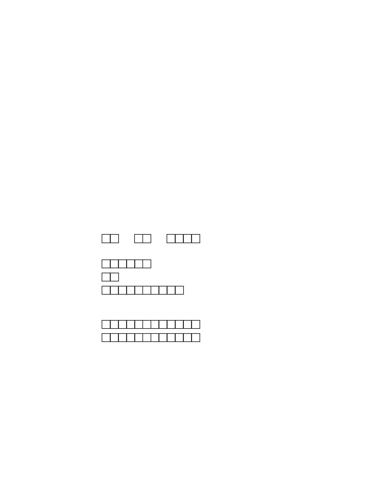
Safety Symbols and Meanings
The safety alert symbol indicates a potential personal
injury hazard. A signal word (DANGER, WARNING, or
CAUTION) is used with the alert symbol to designate a
degree or level of hazard seriousness. A safety symbol
may be used to represent the type of hazard. The signal
word NOTICE is used to address practices not related to
personal injury.
DANGER indicates a hazard which, if not avoided, will
result in death or serious injury.
WARNING indicates a hazard which, if not avoided, could
result in death or serious injury.
CAUTION indicates a hazard which, if not avoided, could
result in minor or moderate injury.
NOTICE addresses practices not related to personal injury.
The manufacturer cannot possibly anticipate every possible
circumstance that might involve a hazard. The warnings in
this manual, and the tags and decals affixed to the unit are,
therefore, not all-inclusive. If you use a procedure, work
method or operating technique that the manufacturer does
not specifically recommend, you must satisfy yourself that
it is safe for you and others. You must also make sure that
the procedure, work method or operating technique that you
choose does not render the generator system unsafe.
Explosion
Fire
Electrical Shock
Rotating Parts
Hot Surface
Toxic Fumes
Chemical BurnExplosive PressureAuto Start
Lift Hazard
Read Manual

5
WARNING Generating set produces hazardous voltage.
Failure to properly ground generating set could
result inelectrocution.
Failure to isolate generating set from utility power
could result in death or serious injury to electric
utility workers due to backfeed of electrical energy.
• Electrical system must meet current requirements when
generating set is installed. This includes the RCD in
distribution panel.
• DO NOT touch bare wires or bare receptacles.
• DO NOT use generating set with electrical cords which are
worn, frayed, bare or otherwise damaged.
• DO NOT handle generating set or electrical cords while
standing in water, while barefoot, or while hands or
feet are wet.
• If you must work around a unit while it is operating,
stand on an insulated dry surface to reduce the risk of
a shock hazard.
• DO NOT allow unqualified persons or children to operate
or service generating set.
• In case of an accident caused by electrical shock,
immediately shut down the source of electrical power and
contact the local authorities. Avoid direct contact with
the victim.
• Despite the safe design of the generating set, operating
this equipment imprudently, neglecting its maintenance or
being careless could cause possible injury or death.
• Remain alert at all times while working on this equipment.
Never work on the equipment when you are physically
or mentally fatigued.
• Before performing any maintenance on the generating set,
disconnect the battery cable indicated by a NEGATIVE,
NEG or (-) first. When finished, reconnect that cable last.
• After your system is installed, the generating set may
crank and start without warning any time there is a
power failure. To prevent possible injury, always set the
generating set’s system switch to OFF, remove the service
disconnect from the disconnect box AND remove the
15 Amp fuse BEFORE working on the equipment.
WARNING Propane and Natural Gas are extremely
flammable and explosive, which could cause
burns, fire or explosion resulting in death,
serious injury and/or property damage.
• Install the fuel supply system according applicable fuel-
gas codes.
• Before placing the generating set into service, the fuel
system lines must be properly purged and leak tested.
• After the generating set is installed, you should inspect
the fuel system periodically.
• NO leakage is permitted.
• DO NOT operate engine if smell of fuel is present or other
explosive conditions exist.
• DO NOT smoke around the generating set. Wipe up
any oil spills immediately. Ensure that no combustible
materials are left in the generator compartment. Keep the
area near the generator clean and free of debris.
WARNING Hazardous Voltage - Contact with power
lines could cause electric shock or burns,
resulting in death or serious injury.
Lifting Hazard / Heavy Object - Could result
in serious injury.
• If lifting or hoisting equipment is used, DO NOT contact
any power lines.
• DO NOT lift or move generating set without assistance.
• Use lifting pipes as described in Lifting the Generating
Set.
• DO NOT lift unit by roof as damage to generating set
will occur.
6
WARNING Starter and other rotating parts could
entangle hands, hair, clothing, or accessories
resulting in serious injury.
• NEVER operate generatng set without protective housings,
covers, or guards in place.
• DO NOT wear loose clothing, jewelry or anything that
could be caught in the starter or other rotating parts.
• Tie up long hair and remove jewelry.
• Before servicing, remove 15 Amp fuse from control panel
and disconnect Negative (NEG or -) battery cable.
CAUTION Installing the 15A fuse could cause the
engine to start at any time without warning
resulting in minor or moderate injury.
• Observe that the 15 Amp fuse has been removed from the
control panel for shipping.
• DO NOT install this fuse until all plumbing and wiring has
been completed and inspected.
CAUTION Excessively high operating speeds could
result in minor injury and/or equipment damage,
Excessively low speeds impose a heavy load on generating
set.
• DO NOT tamper with governed speed. Generator supplies
correct rated frequency and voltage when running at
governed speed.
• DO NOT modify generating set in any way.
NOTICE Improper treatment of generating set could
damage it and shorten its life.
• Use generating set only for intended uses.
• If you have questions about intended use, contact your
authorized dealer.
• Operate generating set only on level surfaces.
• Adequate, unobstructed flow of cooling and ventilating air
is critical to correct generating set operation.
• The access panels/doors must be installed whenever the
unit is running.
• DO NOT expose generating set to excessive moisture,
dust, dirt, or corrosive vapors.
• Remain alert at all times while working on this equipment.
Never work on the equipment when you are physically
or mentally fatigued.
• DO NOT start engine with air cleaner or air cleaner
cover removed.
• DO NOT insert any objects through cooling slots.
• DO NOT use the generating set or any of its parts as a
step. Stepping on the unit could cause stress and break
parts. This may result in dangerous operating conditions
from leaking exhaust gases, fuel leakage, oil leakage, etc.
• Exceeding generating set’s wattage/amperage capacity can
damage unit and/or the electrical devices connected to it.
• If connected devices overheat, turn them off and
disconnect them from generating set.
Shut off generating set if
- electrical output is lost;
- equipment sparks, smokes, or emits flames;
- unit vibrates excessively;
- unit makes unusual noises.
WARNING
Exhaust heat/gases could ignite combustibles
or structures resulting in death, serious
injury and/or property damage. Contact with
muffler area could cause burns resulting in
serious injury.
• DO NOT touch hot parts and AVOID hot exhaust gases.
• Allow equipment to cool before touching.
• Exhaust outlet side of weatherproof enclosure must have
at least 1.5 m minimum clearance from any structure,
shurbs, trees or any kind of vegetation.
• Weatherproof enclosure must be at least 1.5 m from
windows, doors, any wall opening, shrubs or vegetation
over 30.5 cm in height.
• Weatherproof enclosure must have a minimum of 1.5 m
overhead clearance from any structure, overhang or trees.
• DO NOT place weatherproof enclosure under a deck or
other type of structure that may confine airflow.
• Use only flexible fuel line provided. Connect provided fuel
line to generating set, DO NOT use with or substitute any
other flexible fuel line.
• Smoke detector(s) MUST be installed and maintained
indoors according to the manufacturer’s instructions/
recommendations. Carbon monoxide alarms cannot
detect smoke.
• Keep at least minimum distances shown in General
Location Guidelines to insure for proper generating set
cooling and maintenance clearances.
• To use or operate the engine on any forest-covered,
brush-covered, or grass-covered land, contact the original
equipment manufacturer, retailer, or dealer to obtain a
spark arrester designed for the exhaust system installed
on this engine.
• Replacement parts must be the same and installed in the
same position as the original parts.
7
Installation
Equipment Description
This product is intended for use as an optional system
which provides an alternate source of electric power and
to serve loads such as heating, refrigeration systems, and
communication systems that, when stopped during any
power outage, could cause discomfort or inconvenience.
Every effort has been made to ensure that information in this
manual is accurate and current. However, we reserve the
right to change, alter, or otherwise improve the product and
this document at any time without prior notice.
Only current licensed electrical and plumbing
professionals should attempt generating set system
installations. Installations must strictly comply with all
applicable codes, industry standards and regulations.
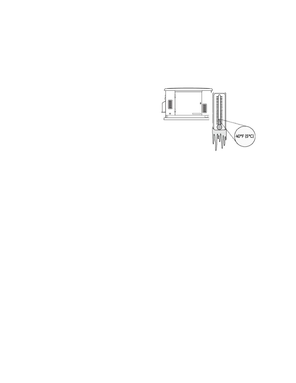
Cold Weather Kit
If operating the generating set below 5°C, it is HIGHLY
RECOMMENDED that a Model 6030A Cold Weather Kit be
installed. These items are available at your local
servicing dealer.
If you need more information on this matter, please visit
www.BRIGGSANDSTRATTON.COM.
Unpacking Precautions
The unit is shipped bolted to its mounting pad, ready
for installation. Avoid damage from dropping, bumping,
collision, etc. Store and unpack carton with the proper side
up, as noted on the shipping carton.
Delivery Inspection
After removing the carton, carefully inspect the generating
set for any damage that may have occurred during shipment.
If loss or damage is noted at time of delivery, have the
person(s) making delivery note all damage on the freight
bill and affix his signature under the consignor’s memo of
loss or damage. If loss or damage is noted after delivery,
separate the damaged materials and contact the carrier
for claim procedures. Missing or damaged parts are
notwarranted.
8
Shipment Contents
The generating set is supplied with:
• Pre-attachedmountingpad
• Fully-servicedoil/lubricatingsystem
• Flexiblefuelhook-uphose
• Installationandstart-upmanual
• Operator’smanual
• Spareaccessdoorkeys
• Spare15AmpATO-typefuse
• Two-pinconnectorplug
• Ten-pinconnectorplug
• Touchuppaint
• RemoteLEDindicatorkit(LED/plate/screws)
Not Included:
• Carbonmonoxidedetector(s)
• Smokedetector(s)
• Startingbattery
• Connectingwireandconduit
• Fuelsupplyvalves/plumbing
• Crane,liftingstraps,chainsorcables
• Two1.2meterlengthsof25mmpipe,3.3mm
minimum thickness (NOT conduit)
• Holepunchesfor1.6mmsteel
• Torquescrewdriver,0.5to5Nmrange
• Voltage/frequencymeter
• Variousspecialtoolsandequipment
Proper installation of the generator requires the completion
of the following tasks:
Carbon Monoxide (CO) Detector
Carbon Monoxide (CO) detector in working order.
Smoke detector in working order.
Placement
Required permits have been obtained.
Generator placed in a Carbon Monoxide (CO) safe
zone. See Placement of Generator to Reduce the
Risk of Carbon Monoxide Poisoning.
Generator placed in a fire safe zone. See Placement
of Generator to Reduce the Risk of Fire.
Generator placed in a water damage safe zone. See
Other General Location Guidelines.
Generator placed in a utility safe zone. See Other
General Location Guidelines.
Generator placed in a debris free zone. See Other
General Location Guidelines.
Fuel
Generator is connected to fuel source with flexible
fuel line, has no fuel leaks and conforms to local
codes. See The Gaseous Fuel System.
Proper fuel pressure has been measured with all
gas appliances operating. See The Gaseous Fuel
System.
Fuel system has been configured for the proper
fuel supply: Natural gas (NG) or liquefied petroleum
( LP). See Fuel Conversion.
Electrical
Generator is grounded. See Grounding the
Generator.
Generator is connected to the transfer switch with
the specified wiring. See Utility Circuit Connection
and Transfer Switch Communication.
Generator is connected to the transfer switch with
the specified wiring. #18AWG twisted pair wiring
from the generator control panel to the transfer
switch is installed in a separate conduit from
high voltage wires unless the insulation rating on
all wiring is rated for 600V See Transfer Switch
Communication.
Dipswitches in most transfer switches must be set
to correspond to the wattage of the generator. See
Transfer Switch Operator/Installation Manual.
Operation
Cold weather kit is installed, if required. See Cold
Weather Kit.
Correct battery type is installed and fully charged.
See Final Installation Considerations.
Generator engine oil level is at full mark. See Final
Installation Considerations.
Utility was shut off to test the operation of generator
and transfer switch. Note any fault codes and make
corrections as required.
Installation Checklist
9
Generating Set Placement
Before installing generating set, consult with owner and convey
the following requirements, which must be satisfied before the
installation is complete.
There are two equally important safety concerns in regards to
carbon monoxide poisoning and fire. There are also several
general location guidelines that must be met before the
installation in considered complete.
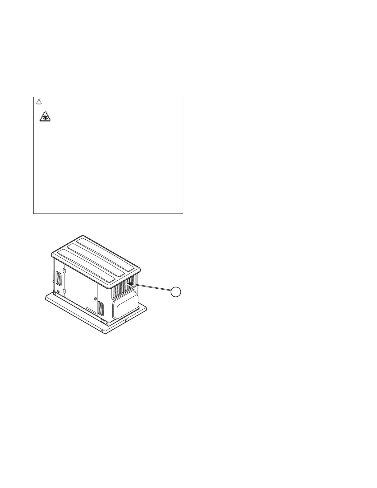
Exhaust Side of the Generating Set
A - Exhaust outlet side of weatherproof enclosure
WARNING Running engine gives off carbon monoxide,
an odorless, colorless, poison gas.
Breathing carbon monoxide could result in death
serious injury, headache, fatigue, dizziness,
vomiting, confusion, seizures, nausea or fainting.
• Operate this product ONLY outdoors in an area that will
not accumulate deadly exhaust gas.
• Keep exhaust gas away from any windows, doors,
ventilation intakes, soffit vents, crawl spaces, open garage
doors or other openings that can allow exhaust gas
to enter inside or be drawn into a potentially occupied
building or structure.
• Carbon monoxide detector(s) MUST be installed and
maintained indoors according to the manufacturer’s
instructions/recommendations. Smoke alarms cannot
detect carbon monoxide gas.
A

10
All fossil fuel burning equipment, such as generating sets,
contains carbon monoxide (CO) gas in the engine exhaust.
CO gas is odorless, colorless and tasteless and is unlikely to
be noticed until a person is overcome. CO gas can kill you
so it is required that the following is included as part of the
installation:
• Installgeneratingsetoutdoorsinanareathatwillnot
accumulate deadly exhaust gas.
• DONOTinstallgeneratingsetwhereexhaustgas
could accumulate and enter inside or be drawn into a
potentially occupied building or structure.
• ItmayberequiredtohaveaCarbonMonoxide(CO)
detector in operating condition in your. Carbon
monoxide detector(s) (A) MUST be installed and
maintained indoors according to the manufacturer’s
instructions / recommendations. A CO monitor is an
electric device that detects hazardous levels of CO.
When there is a buildup of CO, the monitor will alert the
occupants by flashing visual indicator light and alarm.
Smoke alarms cannot detect CO gas.
• Yourneighbor(s)maybeexposedtotheengine
exhaust and exhaust noise from your generating set
and must be considered when installing.
• Ensureexhaustgasiskeptawayfrom:
B - windows
C - doors
D - ventilation intakes
E - soffit vents
F - garage doors
G - crawl spaces or other openings that can allow
exhaust gas to enter inside or be drawn into a
potentially occupied building or structure.
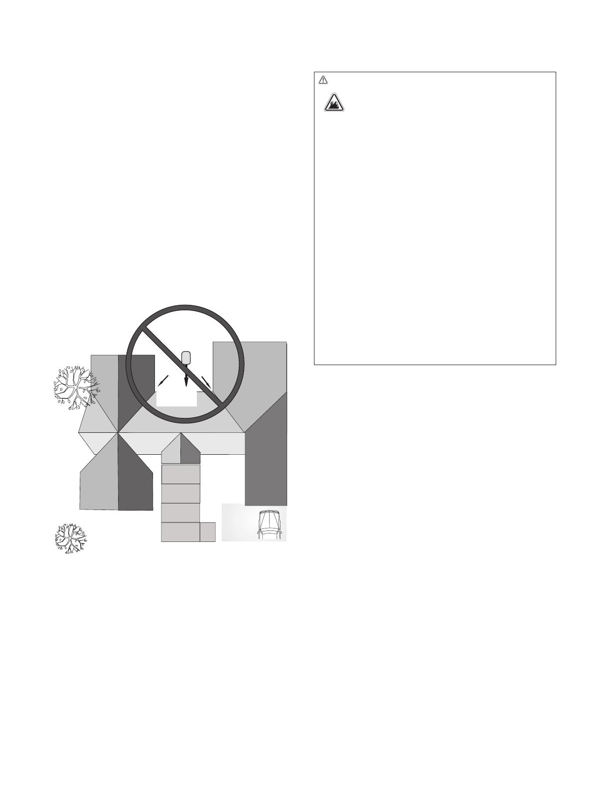
Placement Generating Set to REDUCE THE RISK OF CARBON MONOXIDE POISONING
The arrows in the figure below point to POTENTIAL points of entry for Carbon Monoxide Gas.
A
F
C
D
B
E
G
11
• Directthegeneratingsetexhaustawayfromor
parallel to the building or structure. DO NOT direct the
generating set exhaust towards a potentially occupied
building, structure, windows, doors, ventilation intakes,
soffit vents, crawl spaces, open garage doors or other
openings where exhaust gas could accumulate and
enter inside or be drawn into potentially occupied
building or structure.
• DONOTplacegeneratingsetinanyareawhereleaves
or debris normally accumulates. Position generating set
in an area where winds will carry the exhaust gas away
from any potentially occupied building or structure.
WARNING
Exhaust heat/gases could ignite combustibles
or structures resulting in death, serious injury and/
or property damage.
• Exhaust outlet side of weatherproof enclosure must have
at least 1.5 m minimum clearance from any structure,
shrubs, trees or any kind of vegetation.
• Generating set’s weatherproof enclosure must be at least
1.5 m from windows, doors, any wall opening, shrubs or
vegetation over 30.5 cm in height.
• Generating set’s weatherproof enclosure must have
a minimum of 1.5 m overhead clearance from any
structure, overhang or trees.
• DO NOT place weatherproof enclosure under a deck or
other type of structure that may confine airflow.
• Use only flexible fuel line provided. Connect provided fuel
line to generator, DO NOT use with or substitute any other
flexible fuel line.
• Smoke detector(s) MUST be installed and maintained
indoors according to the manufacturer’s instructions/
recommendations. Carbon monoxide alarms cannot
detect smoke.
• DO NOT place weatherproof enclosure in manner other
than shown in illustrations.
Generating
Set
Exhaust
Gas
12
Examples of generating set locations to reduce
the risk of fire:
Legend for Generating Set Locations to reduce the risk of
fire:
A - Generator set’s weatherproof enclosure must be at
least 1.5 m from windows, doors, any wall opening,
shrubs, or vegetation over 30.5 cm in height.
B - Exhaust outlet side of weatherproof enclosure
must have at least 1.5 m minimum clearance from any
structure, overhang or trees.
C - Generating set’s weatherproof enclosure must have
a minimum of 1.5 m overhead clearance from any
structure, overhang, or trees.
NOTICE DO NOT place weatherproof enclosure under a deck
or other type of covered structure that may confine airflow.
Single Combustible Structure Installation
A
Generating
Set
Exhaust
Direction
A
B
Generating
Set
A
Exhaust
Direction
B
1.5 m min.
1.5 m
1.5 m min.
1.5m min.
13
Legend for Generator Locations to reduce the risk of fire:
A - Generating set’s weatherproof enclosure must be
at least 1.5 m from windows, doors, any wall opening,
shrubs, or vegetation over 30.5 cm in height.
B - Exhaust outlet side of weatherproof enclosure
must have at least 1.5 m minimum clearance from any
structure, overhang or trees.
C - Generating set’s weatherproof enclosure must have
a minimum of 1.5 m overhead clearance from any
structure, overhang, or trees.
Dual Combustible Structure Installation
A
A
A
A
1.5 m min.
Exhaust
Direction
Generating
Set
B
1.5 m min.
Generating
Set
Exhaust
Direction
Exhaust
Direction
B
C
B
1.5 m min.
1.5 m min.
1.5 m min.
1.5 m min.
Center of
Exhaust Panel
1.5 m min.
1.5 m min.
14
Single Structure Installation with Structure Having a Fire Resistance Rating of at Least 1 Hour
Legend for Generating Set Locations to reduce the risk of
fire:
A - Generating set’s weatherproof enclosure must be
at least 1.5 m from windows, doors, any wall opening,
shrubs, or vegetation over 30.5 cm in height.
B - Exhaust outlet side of weatherproof enclosure
must have at least 1.5 m minimum clearance from any
structure, overhang or trees.
C - Generator set’s weatherproof enclosure must have
a minimum of 1.5 m overhead clearance from any
structure, overhang, or trees.
NOTICE DO NOT place weatherproof enclosure under a deck
or other type of covered structure that may confine airflow.
A
Exhaust
Direction
Generating Set
A
B
A
Generating
Set
Exhaust
Direction
B
A
A
Exhaust
Direction
Generating Set
B
1.5 m min.
0.6 m min.
1.5 m min.
1.5 m min.
0.6 m min.
1.5 m min.
1.5 m min.
0.9 m min.
1.5 m min.
15
Dual Structure Installation with Structure Having a Fire Resistance Rating of at Least 1 Hour
Legend for Generator Locations to reduce the risk of fire:
A - Generating set’s weatherproof enclosure must be
at least 1.5 from windows, doors, any wall opening,
shrubs, or vegetation over 30.5 cm in height.
B - Exhaust outlet side of weatherproof enclosure
must have at least 1.5 m minimum clearance from any
structure, overhang or trees.
C - Generating set’s weatherproof enclosure must have
a minimum of 1.5 m overhead clearance from any
structure, overhang, or trees.
NOTICE DO NOT place weatherproof enclosure under a deck
or other type of covered structure that may confine airflow.
Other General Location Guidelines
• Placethegeneratingsetinapreparedlocationthatis
flat and has provisions for water drainage.
• Installthegeneratingsetinalocationwheresump
pump discharge, rain gutter down spouts, roof run-
off, landscape irrigation, or water sprinklers will not
flood the unit or spray the enclosure and enter any
air inlet or outlet openings.
• Installthegeneratingsetwhereitwillnotaffector
obstruct any services including covered, concealed
and underground, such as telephone, electric, fuel
(natural gas / LPG vapor), irrigation, air conditioning,
cable, septic, sewer, well and so forth.
• Installthegeneratingsetwhereleaves,grass,snow,
etc. will not obstruct air inlet and outlet openings. If
prevailing winds will cause blowing or drifting, you
may need to construct a windbreak to protect the
unit.
• Allowsufficientroomonallsidesofthegenerating
set for maintenance and servicing.
A
A
Generating
Set
Exhaust
Direction
B
A
A
A
A
Generating
Set
Exhaust
Direction
B
0.9 m
Generating
Set
Exhaust
Direction
B
0.6 m min.
1.5 m min.
1.5 m min.
0.6 m min.
1.5 m min.
1.5 m min.
1.5 m min.
0.6 m min.
1.5 m min.
min.
0.6 m
min.
16
Electrical and Fuel Inlet Locations
The 19mm N.P.T. fuel inlet connector (B) and electrical inlet
location (A) is shown here:
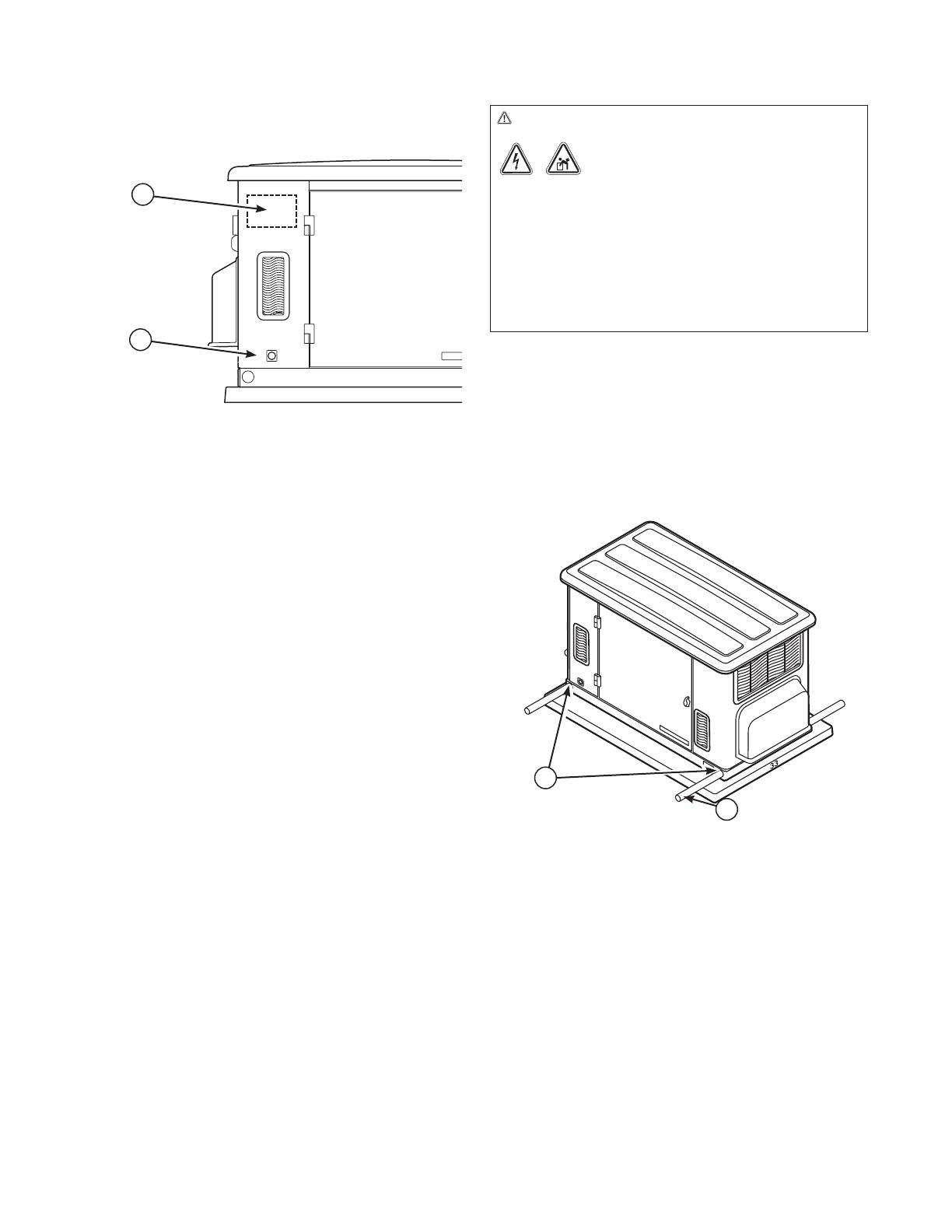
Lifting the Generating Set
The generating set weighs more than 240 kg. Proper tools,
equipment and qualified personnel should be used in all
phases of handling and moving the generating set.
Two 1.2m lengths of size 6 scaffold tube (33.7mmOD x
25mmID to EN39) or equivalent are required to lift the
generating set (C). Insert these tubes through the lifting
holes (D) located near the unit’s base. Position the tubes so
that equal length’s protrude from each side.
You may also lift the unit using a “hook and hoist” method
attached to the lifting pipes, provided that you use a spreader
bar to ensure that the chains or cables DO NOT touch the
generating set’s roof.
After unit is in place, fill the lifting holes with the supplied
lifting hole plugs. Retouch any chipped paint with supplied
touch-up paint.
A
B
C
D
WARNING Hazardous Voltage - Contact with power
lines could cause electric shock or burns,
resulting in death or serious injury.
Lifting Hazard / Heavy Object - Could result
in serious injury.
• If lifting or hoisting equipment is used, DO NOT contact
any power lines.
• DO NOT lift or move generating set without assistance.
• Use lifting pipes as described in Lifting the Generating
Set.
• DO NOT lift unit by roof as damage to generating set
will occur.

17
Access Ports
The generating set is equipped with an enclosure that has
several access doors, as shown. The doors are named for a
significant component located behind them, as follows:
A - Control Panel door (cover to be attached by installer)
B - Fuel Inlet Port (shown for reference)
C - Oil Drain door
D - Oil Fill door
E - Exhaust Port
The access doors must be installed whenever the unit
is running to assure proper cooling, reduce noise and for
added safety.
Each generating set is shipped with a set of identical keys.
These keys fit the locks that secure the access ports.
To open access door:
1. Insert key into lock of access door handle and turn key
one quarter turn counterclockwise.
2. Grasp door’s handle and turn one quarter turn
counterclockwise to open. Remove key.
To close access door:
1. Close door and turn door’s handle one quarter
turnclockwise.
2. Insert key into lock of door handle and turn key one
quarter turn clockwise. Remove key.
BA C D E
WARNING Contact with the muffler area can result in
serious burns.
• DO NOT touch hot parts and AVOID hot exhaust gases.
• Allow equipment to cool before touching.
18
The Gaseous Fuel System
The information below is provided to assist gaseous fuel
system technicians in planning installations. In no way
should this information be interpreted to conflict with
applicable fuel gas codes. Consult with your local fuel
supplier or Fire Marshall if questions or problems arise.
TO THE INSTALLER: Consult with the generating set
owner(s) and convey any technical considerations that
might affect their installation plans before applying these
general guidelines.
The following general rules apply to gaseous fuel
system piping:
• Thepipingshouldbeofamaterialthatconformsto
federal and local codes, rigidly mounted and protected
against vibration.
• Pipingshouldbeprotectedfromphysicaldamage
where it passes through flower beds, shrub beds, and
other cultivated areas where damage could occur.
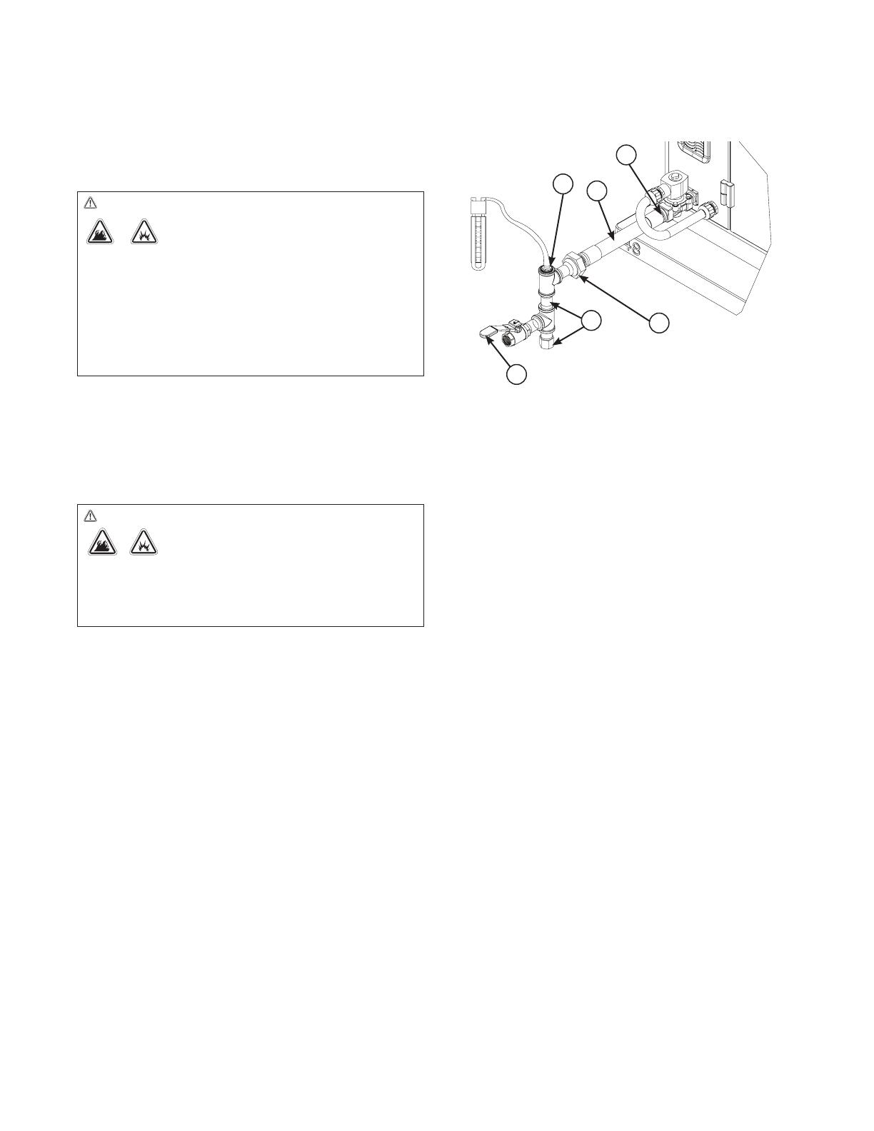
• Installtheflexiblesteelfuelline(B) (supplied) between
the generating set fuel inlet port (A) and rigid piping to
prevent thermal expansion or contraction from causing
excessive stress on the piping material.
• Aunion(C) or flanged connection shall be provided
downstream to permit removal of controls.
• Amanometerportshouldbeprovided(D). When
the initial test runs are completed, the manometer
is removed and the port is plugged. The manometer
port permits temporary installation of a manometer
to ensure that the engine receives the correct fuel
pressure to operate efficiently throughout its operating
range.
• Wheretheformationofhydratesoriceisknownto
occur, piping should be protected against freezing. The
termination of hard piping should include a sediment
trap (F) where condensate is not likely to freeze.
• Aminimumofoneaccessible,approvedmanualshutoff
valve (E) shall be installed in the fuel supply line within
180 cm of the generating set.
• Amanualfuelshut-offvalvelocatedintheinteriorof
the building.
• Wherelocalconditionsincludeearthquake,
tornado, unstable ground, or flood hazards, special
consideration shall be given to increase strength and
flexibility of piping supports and connections.
• Pipingmustbeifthecorrectsizetomaintainthe
required supply pressures and volume flow under
varying generating set load conditions with all gas
appliances connected to the fuel system turned on and
operating.
• Useapipesealantorjointcompoundapprovedfor
use with NG/LPG on all threaded fittings to reduce the
possibility of leakage.
• Installedpipingmustbeproperlypurgedandleak
tested, in accordance with applicable codes and
standards.
Fuel Pressure
Both LP vapor and natural gas fuel supply pressure at
the generating set’s fuel inlet port should be between the
following levels at full load with all gas appliances turned on
and operating.
• NGis12-17millibar
• LPis27-35millibar
Ensure that all gas line shutoff valves are OPEN and that
adequate fuel pressure is available whenever automatic
operation is desired.
Power Loss
Air density is less at high altitudes, resulting in less available
engine power. Specifically, engine power will decrease 3.5%
for each 300 meters above sea level and 1% for each 5.6°C
above 25°C. Make sure you and your installer consider these
factors when determining total generating set load.
B
A
C
D
F
E
WARNING Propane and Natural Gas are extremely
flammable and explosive, which could cause
burns, fire or explosion resulting in death,
serious injury and/or property damage.
• LP gas is heavier than air and will settle in low areas.
• Natural gas is lighter than air and will collect in high
areas.
• The slightest spark could ignite these fuels and cause an
explosion.
• DO NOT light a cigarette or smoke.
WARNING Propane and Natural Gas are extremely
flammable and explosive, which could cause
burns, fire or explosion resulting in death,
serious injury and/or property damage.
• Before placing the generating set into service, the fuel
system lines must be properly purged and leak tested.
• No leakage is permitted.
19
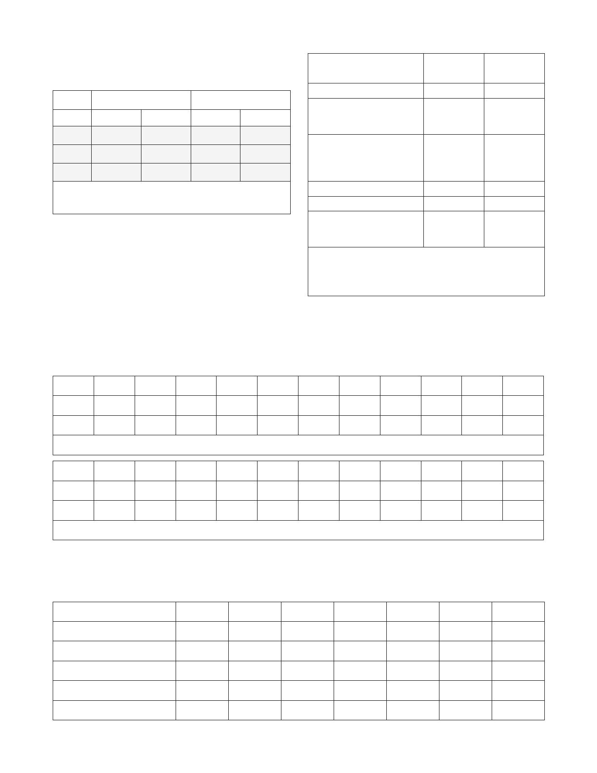
Fuel Consumption
Estimated fuel supply requirements at half and full load for
natural gas and LP vapor fuels are shown below.
Natural Gas LP Vapor
1/2 Load Full Load 1/2 Load Full Load
12.5 kW 3.5 C 6.9 C 1.6 C 3.0 C
133 MJ 255 MJ 147 MJ 283 MJ
126,000 B 242,000 B 140,000 B 270,000 B
C = Cubic meters per hour
MJ = megajoules per hour
B = BTU’s per hour
Physical Properties LP Vapor Natural
Gas
Normal Atmospheric State Gas Gas
Boiling Point (in °F):
Initial
End
-44
-44
-259
-259
Heating Value:
BTU per gallon (Net LHV*)
BTU per gallon (gross**)
Cubic feet (gas)
83,340
91,547
2,500
63,310
1,000
Density*** 36.39 57.75
Weight† 4.24 2.65
Octane Number:
Research
Motor
110+
97
110+
* LHV (Low Heat Value) is the more realistic rating.
** Gross heat value does not consider heat lost in the form of water
during combustion.
*** Density is given in “Cubic Feet of Gas per Gallon of Liquid”.
† Weight is given in “Pounds per Gallon of Liquid”.
NPT 3m 4.5m 6m 9m 12m 15m 18m 21m 24m 27m 30m
3/4” 9.8 8.3 6.8 5.4 4.6 4.1 3.7 3.4 3.2 3.0 2.8
1” 18.5 15.5 12.6 10.2 8.7 7.8 7.1 6.5 6.0 5.6 5.3
Natural Gas Pipe Size - Gas Flow chart, in cubic feet per hour, specific gravity=0.65
NPT 3m 4.5m 6m 9m 12m 15m 18m 21m 24m 27m 30m
3/4” 7.8 5.4 4.5 3.6 3.0 2.7 2.5 2.2 2.1 2.0 1.8
1” 12.1 10.2 8.3 6.7 5.7 5.1 4.6 4.3 3.9 3.7 3.5
Liquid Propane (LP) Gas Pipe Size - Gas Flow chart, in cubic feet per hour, specific gravity=1.50
Fuel Pipe Sizing
The tables below provide the maximum capacity of pipe in cubic feet of gas per hour for gas pressures of 35 mbar or less and
a pressure drop of 0.7 mbar water column. Specific gravity of gas is shown.
Listed values compensate for a nominal amount of restriction from bends, fittings, etc. If an unusual number of fittings, bends,
or other restrictions are used, please refer to federal and local codes.
Withdrawal Rate 0° C -7° C -12° C -18° C -23° C -35° C -40° C
50 CFH 115 115 115 250 250 400 600
100 CFH 250 250 250 400 500 1000 1500
150 CFH 300 400 500 500 1000 1500 2500
200 CFH 400 500 750 1000 1200 2000 2500
300 CFH 750 1000 1500 2000 2500 4000 5000
Required Propane Tank Size
The required size of the propane tank at various temperatures when kept at least half full is shown below in the chart. Given
the gas withdrawal rate and the lowest average winter temperature, an installer can specify the required LP storage tank size.
20
B
A
C
D
E
F
G
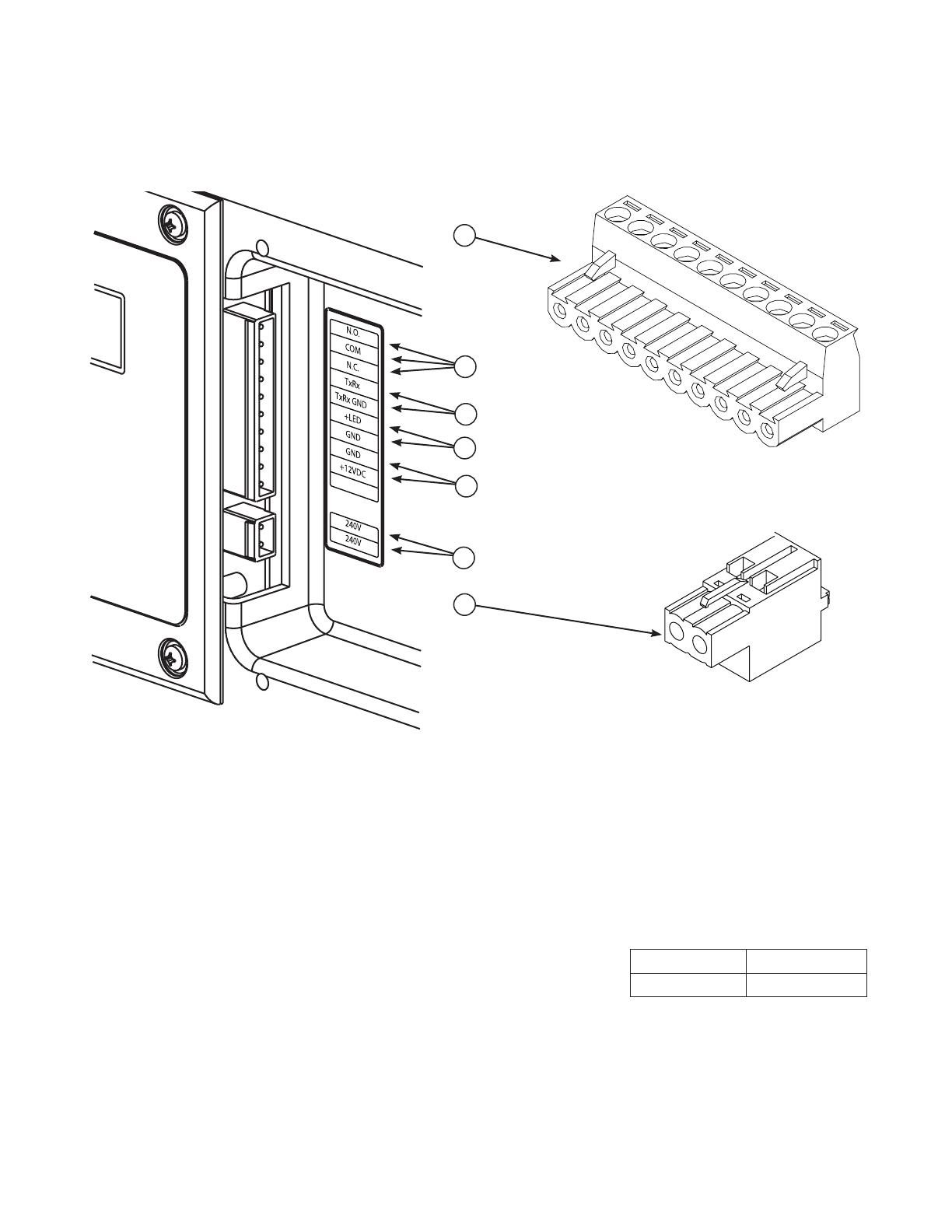
System Connectors
Except for the power output and grounding connectors, all signal wire connections are made to removable two- or ten-pin
connector plugs. Compare this illustration with your generating set to familiarize yourself with the location of these important
connections. Count down to the proper pin location on the control board since visual alignment with the decal can
bemisleading:
A - Ten-pin Connector Plug
B - Fault Contacts — Use NO, COM and NC to hook up a
siren, light, etc. to alert you in case of a fault. Contacts
reverse state (NO goes to NC and vice versa) upon a
faultcondition.
C - Transfer Switch Communication — Connect to transfer
switch control board for communication interface using
18AWG copper twisted pair wire.
D - Remote LED Output — Use this to hook up the optional
remote LED. The remote LED will turn on and off in
a series of blinks if certain faults are detected in the
generator.
E - +12 Volt DC, .5 Amp Output — Internal power supply.
F - 230 Volt Utility — Use to hook up the 230V utility leads
from the transfer switch to the generator.
G - Two-pin Connector Plug
• Forgeneratoroutputconnection,use16mm²minimum300volt75°C-90°C
copper wire
• ForUtilityCircuitconnectionuse2.58mm²minimum300volt75°C-90°C
copperwire.
• Fortransferswitchcommunicationuse0.82mm²twistedpairconductors,no
greater than 200 ft in length, 300 volt 75°C-90°C copper wire.
• Whenconnectingtotheconnectorplugs,fastenonlyonewiretoeach
connectorscrew.
• Torqueconnectorplugscrewsto7.9Newtonmeter.
Generator Wire Size (mm²)
12.5 kW 16
/