Page is loading ...

OPENING RECEIVER
1
B(Yellow)
A(Grey)
CONTROL
STATION
COAXIAL
RECEIVER
Example of Operator
Terminal Strip
C(Blue)
2
3
4
24Vac
Wire nut
STOP
COMMON
CLOSE
CLOSE
OPEN
STOP
OPEN
The receiver can be used with a multi-function remote
control to operate three residential garage door openers, or
with a three-button door control to OPEN, CLOSE or STOP a
commercial garage door opener. Not for use on residential
fail-safe operators.
INSTALLATION
The receiver and antenna use TV Type F coaxial connectors. The
antenna can be plugged directly into the receiver or mounted to a
bracket and connected to the receiver with Model 86 Coaxial
Cable Kit, depending on your requirements.
Select a location for the receiver which allows access to the
terminals and space for the antenna (as far from metal structures
as possible and preferably with the antenna in an upright
position). Fasten the receiver securely with screws through the
two holes provided in the cover flanges.
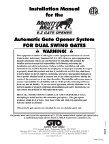
To use the receiver with a 3-button door control
and a commercial door opener:
Consult your manufacturer’s control connection diagram for
instructions on connecting two or more 3-button control devices.
Figure 1.
• Use a screwdriver to pry open the receiver cover.
NOTE: The slide switch is factory set to the N.C. position (other-
wise the opener will not operate). Verify this setting. Re-connect
power to the opener and the accessory transformer, if used.
Figure 1
To prevent possible SERIOUS INJURY or DEATH from electrocution:
• Be sure power is not connected BEFORE installing the receiver.
To prevent possible SERIOUS INJURY or DEATH from a moving gate
or garage door:
• ALWAYS keep remote controls out of reach of children. NEVER
permit children to operate, or play with remote control transmitters.
• Activate gate or door ONLY when it can be seen clearly, is properly
adjusted, and there are no obstructions to door travel.
• ALWAYS keep gate or garage door in sight until completely closed.
NEVER permit anyone to cross path of moving gate or door.
WARNING
CAUTION
WARNING
WARNING
To prevent possible SERIOUS INJURY or DEATH, the use of
CONSTANT OPERATION on residential openers is PROHIBITED.
WARNING
CAUTION
WARNING
WARNING
3-Channel Receiver
Model 323LM
OWNERS MANUAL
When a receiver is used to activate a commercial door opener, a
reversing edge MUST be installed on the bottom of the door. Failure
to install a reversing edge under these circumstances may result in
SERIOUS INJURY or DEATH to persons trapped beneath the door.
WARNING
CAUTION
WARNING
WARNING
1
ABC
Connect
Antenna
Open
Close
Stop
Slide Switch – N.C. Position
• Select a remote control push button to STOP the opener. (It is recommended that you use the large button on remote).
• Press and hold the selected remote push button.
• Then press and release the “learn” button labeled “A” on the receiver. The adjacent indicator light will FLASH.
• Release the remote push button.
Repeat the procedure above with a second remote push button and receiver “learn” button “B” to program the OPEN operation;
and again with the last remote push button and receiver “learn” button “C” to program the CLOSE function of the opener.
Return the front cover to the receiver.
NOTE: If a remote control push button is not pressed within 30 seconds, the indicator light adjacent to the selected “learn” button will
turn OFF. In that case, repeat the programming.
Figure 2

ABC
Select a remote control
push button to operate
each opener
Connect
Antenna
Opener #3
(Blue)
Opener #2
(Yellow)
Opener #1
(Grey)
Slide Switch – N.O. Position
To use the receiver to operate three garage
door openers with a multi-function
remote control:
Garage door opener no. 1 (without transformer)
Refer to Figure 3 for wiring connections:
Connect paired grey receiver wires to the opener terminal screws
used for the wall push button.
Also, connect bell wire to receiver terminal 1 and opener terminal
screw 1; and receiver terminal 2 and opener terminal screw 3.
Garage door opener no.1 (with transformer 95)
Refer to Figure 4 for wiring connections:
Connect bell wire to receiver terminal screws 1 and 2, and to
transformer terminals. Also, connect paired grey receiver wires to
opener terminal screws used for wall push button.
Garage door opener no. 2: Connect paired yellow wires from
the receiver to the opener terminal screws used for the wall
button.
Garage door opener no. 3: Connect paired blue wires from the
receiver to the opener terminal screws used for the wall button.
Use a screwdriver to pry open the receiver cover.
Set the slide switch to the N.O. position. If this is not done,
opener #1 may not operate properly.
Re-connect power to the opener(s) and to the transformer,
if used.
• Select a remote push button to operate garage door opener #1.
• Press and hold the selected remote button. Then press and
release the “learn” button labeled “A” on the receiver. The
adjacent indicator light will FLASH.
• Release the remote push button. Opener #1 will now operate
when the selected remote control push button is pressed.
Repeat the procedure with the other two remote push buttons to
program the second opener (“learn” button “B”) and the third
opener (“learn” button “C”). Figure 5.
Return the cover to the receiver.
NOTE: If opener #1 will not run, check to be sure the slide
switch on the receiver is set to the N.O. position.
NOTE: If a remote control push button is not pressed within 30
seconds, the indicator light adjacent to the selected “learn” button
will turn OFF. In that case, repeat the programming.
1
2
3
1
3
Receiver
(Bottom)
Wall
Button
Operator
24 v
Trans
Primary
4
Common
2
Relay
Transformer 95
Paired grey receiver wires
1
2
3
1
2
3
Receiver
(Bottom)
Paired grey receiver wires
Operator
24 v
Trans
Primary
4
Common
Relay
Wall
Button
Figure 3
Figure 4
© 2005, The Chamberlain Group, Inc.
114A3098 All Rights Reserved Printed in Mexico
Figure 5
NOTICE: To comply with FCC and or Industry Canada (IC) rules, adjustment or modifications of this
receiver and/or transmitter are prohibited, except for changing the code setting or replacing the bat-
tery. THERE ARE NO OTHER USER SERVICEABLE PARTS.
Tested to Comply with FCC Standards FOR HOME OR OFFICE USE. Operation is subject to the fol-
lowing two conditions: (1) this device may not cause harmful interference, and (2) this device must
accept any interference received, including interference that may cause undesired operation.
SPECIFICATIONS
Output Rating......................................5 Amps 28VAC or DC Max.
Power.......................................................18 - 30V ~, 30mA, 60Hz
18 - 30V , 30mA
RF Frequency...................................................................315 MHz
If the power is other than shown in specifications, Accessory
Transformer Model 95 is required. Model 86 Coaxial Cable Kit is
also available.
Accessory Transmitters — Series 300.
/