Traveler Any Spot Traveler AS-TV8 User manual
- Category
- Soundbar speakers
- Type
- User manual
This manual is also suitable for

USER'S GUIDE
Wireless Portable Sound System
Compact, Lightweight
Clear sound quality
High output power
TRAVELER
ANY SPOT
ANY SP T O
®
AS-TV8
TM
®

Contents
Operating Manual for AS-TV8 Series.....................................................1
Front Panel Configuration of AS-TV8 Series..........................................2
Rear Panel Configuration of AS-TV8 Series ..........................................3
Description of Functions of AS-TV8 Series...........................................6
Caution Before Using the System..........................................................9
Installation and Operation of Portable Sound System............................9
Wireless Mic/Receiver Audio Link..........................................................9
Anti Shock CD/CMP Player...................................................................10
Tone Controls........................................................................................10
In/Out Jacks..........................................................................................11
Speaker Out..........................................................................................11
Digital Echo System..............................................................................11
Audio Link Transmitter..........................................................................11
Description of Functions for Handheld Microphone Front....................13
Description of Functions for Handheld Microphone Back.....................14
Operation of Handheld Microphone......................................................15
Description of Functions for Body Pack Transmitter.............................18
Operation of Body Pack Transmitter.....................................................19
Maintenance.........................................................................................21
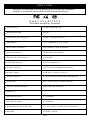
Specifications..................................................................................22-26
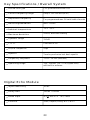
Key Specs/Overall System...................................................................23
Digital Echo Module..............................................................................23
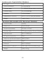
Audio Link Transmitter Module.............................................................24
Receiver Module...................................................................................24
Handheld Microphone..........................................................................25
Bodypack Transmitter...........................................................................26

Operating Manual for AS-TV8 Series
**Please visit for the latest updates**www.galaxyaudio.com
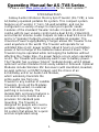
Introduction
1
Galaxy Audio introduces the Any Spot Traveler (AS-TV8); a new
AC/battery operated portable PA system. This compact system
features an 8” woofer, 1” horn, 50-watt amplifier, and can be
configured in a variety of ways to meet your specific needs.
Features of the standard Traveler include: 2 Inputs (XLR/1/4”
combo with its own volume control and a dual RCA), 2 Band EQ,
and a Master Volume. Audio Outputs include a dual RCA Line Out
and a ¼” Speaker Output to power an additional speaker. The
Universal Power Supply/Battery Charger allows the Traveler to be
used anywhere in the world. The Traveler will operate for an
unlimited time on AC power and for about 6 hours on just battery
power. A full recharge of the batteries takes about 4 hours. The
Traveler may be operated while recharging the batteries without
affecting the charge time. If a power failure occurs when operating
on AC, the Traveler will seamlessly switch over to battery power.
The Traveler has a unique “plug in” modular design, which allows
optional Function Modules to be easily added or removed. Optional
Modules include Wireless Mic Receivers (with Handheld, Headset,
& Lapel options), a CD/MP3 player, and the choice of an
Echo/Delay unit or an Audio Link Module,
which wirelessly transmits the
entire audio mix from one
Traveler to any number of satellite
Travelers. Since all the Modules
are internally wired, no external
patching is necessary. The
durable ABS enclosure features a
convenient carry handle and a
provision for standard pole
mounting. The Traveler is
designed for people who need a
portable, lightweight, “all in one”
PA system that allows for a quick
and uncomplicated setup.

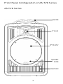
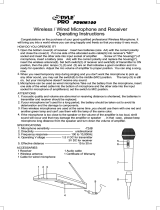
Front Panel Configuration of AS-TV8 Series
AS-TV8 Series
2
Heat Sink
Speaker
Grille
8" Woofer
1" Horn
Handle

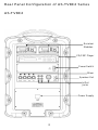
Rear Panel Configuration of AS-TV8C2 Series
AS-TV8C2
Power Supply
In/Out
Jacks
Speaker Out
Mixer
Power Switch
CD/CMP Player
Receiver
Modules
3

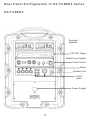
AS-TV8CE2
Mixer
Receiver
Modules
CD/CMP Player
Digital Echo System
Power Switch
Speaker Out
In/Out
Jacks
Power Supply
4
Rear Panel Configuration of AS-TV8CE2 Series

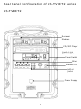
AS-TV8CT2
Mixer
Receiver
Modules
CD/CMP Player
Audio Link
Transmitter
Speaker Out
In/Out
Jacks
Power Supply
Power Switch
5
Rear Panel Configuration of AS-TV8CT2 Series

6
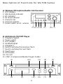
Description of Functions for AS-TV8 Series
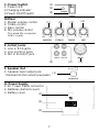
A. Wireless Microphone/Audio Link Receiver
1. LCD display
2. A/B diversity indicator
3. RF indicator
4. AF level indicator
5. Channel Set
6. Channel selector
7. Power switch & mic. volume
B. Anti-Shock CD/CMP Player
1. Program Playlist
2. Power switch
3. LCD display
4. Shuffle/Repeat
5. Stop/Eject
6. Search and play the previous track
7. Search and play the next track
8. Play/Pause
9. CD volume
10. CD slot
11. CMP Folder(Compressed Media Player)
(2)(1) (3)(4) (5) (6) (7)
(1)
(2) (3)
(5)(4) (8)
(9)
(10)
(11) (6) (7)

(3)
(2)
(1)
(2)(1) (3)
(4)
(2)(1) (3)
(1)
(1)
(2)
(3)
C. Power Switch
1. Power LED
2.Charging indicator
3.Power On/Off switch
D.Mixer
1. Master volume control
2. Treble control
3. Bass control
4. Mic volume control
(For wired Mic connected
to Mic in jack)
E. In/Out Jacks
1. Line in RCA jacks
2. Line out RCA jacks
3. Mic in XLR/1/4" jack
F. Speaker Out
1. Speaker level output jack.
Minimum 8 ohm external speaker
G. Power Supply
1. AC Power Cable connector
2. Batteries (behind cover)
3. Battery cover
7

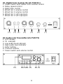
H1. Digital Echo System (for AS-TV8CE2 )
1. Power switch and master echo volume control
2. Delay repeat control
3. Delay time control
4. Wired mic 1 volume control
5. Wired mic 2 volume control
6. Wired mic 1 1/4” input jack
7. Wired mic 2 1/4” input jack
H2. Audio Link Transmitter (AS-TV8CT2)
1. LCD display
2. TX indicator
3. Low audio level indicator
4. High audio level indicator
5. Enter Setting
6. Channel selector
7. Power switch and volume control
(1)
(1)
(2)
(2)
(3)
(3)
(4)
(4)
(5)
(5)
(6)
(6)
(7)
(7)
8
ECHO
REPEAT
DELAY
MIC 1
MIC 2
MIC 1
MIC 2

9
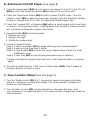
Cautions Before Using the System
1. There is a universal AC switching power supply/charger built into the system
that will operate on voltages of 100~240V,50/60Hz. Verify that the voltage to
which you are connecting is in that range and then connect the AC power
cord from the AC IN (G1) Pg. 7 to the wall outlet.
2. Charge the battery for at least 8 hours with the Power Switch OFF prior to first
time use to maintain the quality of the battery and provide maximum operation
time. When charging, the charging indicator (C2) Pg. 7 lights RED. When
charging is almost complete, the indicator will flash RED and GREEN. After the
battery is fully charged, the indicator lights GREEN. After the initial charge the
Traveler may be operated on either AC or Battery power. When operating on
AC power the Traveler will simultaneously recharge its internal batteries.
3. This system has auto protection circuitry for the battery that will protect the
battery from being overcharged or overused. When running on battery power
and the power switch LED (C1) Pg. 7 lights RED, the battery power is down to
30%. When the power switch flashes repeatedly, the battery is nearly
exhausted and the system will turn off automatically to protect the battery.
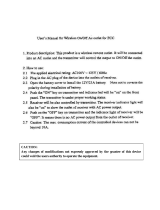
Installation and Operation of Portable Sound System
A. Wireless Mic/Audio link Receiver (see page 6)
This system includes one or two receivers with selectable PLL 96 channel
operation. These modules receive signals from wireless Mics or from another
Traveler equiped with an Audio Link Transmitter.
1. Turn the power switch (A7) pg. 6 clockwise to turn on the receiver.
2. The LCD display (A1) will show "On" and the channel that was last in use
when the unit was turned off.
3. To select a different channel, press the set button (A5). The channel number
will flash in the in LCD display. Press the up or down button (A6) to select a
channel to use, and then press the set button. After a channel has been set,
press either the up or down button to display the frequency of the selected
channel.
4. Adjust the volume control to a usable level.
5. When receiving signal, the A/B diversity indicator (A2) will light RED or
Green to show the normal condition. The RF indicator (A3) will light to show
RF received and the AF indicator (A4) will show audio received.

10
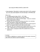
B. Anti-Shock CD/CMP Player (see page 6)
1. Push the powerswitch (B2) Pg. 6 to turn on the player. Put a CD in the CD slot
(B10) or push the Stop/Eject button (B5) to take a CD out of the slot.
2. Press the Play/Pause button (B8) to start or pause CD/MP3 play .Turn the
volume control (B9) to adjust to the proper volume. Push the Stop/Eject button
to stop or change the CD or CMP (Compressed Media Player) disc.
3. Press the Forward (B7) or Reverse (B6) button to skip forward to the next track
or reverse to the previous track. Holding down the Forward or Reverse button
will continuously forward or reverse the tracks.
4. Repeat/Shuffle (B4) has three modes:
1. Repeat one song
2. Repeat all songs
3. Shuffle for random play.
5. Create Program Playlist:
Step 1: Press Prog button (B1) to begin setting up the program playlist
Step 2: Select a song (see step 3 and 6)
Step 3: Press Repeat (B4) to enter the song. Repeat steps 2 and 3 to enter
additional songs.
Step 4: Press Play (B4) to play the programmed songs in memory
*Please note that the program will reset once the Program button is pressed
again.
6. To select a folder from an CMP, press Folder button (B11). Use Forward or
Reverse buttons to select a song.
C. Tone Controls (Mixer) (see the page 7)
1. Turn the Treble control (D2) Pg. 7 counterclockwise to decrease the treble,
and turn clockwise to increase the treble. The center position (straight up)
produces a flat response.
2. Turn the Bass control (D3) counterclockwise to decrease the bass, and
turn clockwise to increase the bass. The center position (straight up) produces
a flat response.

11
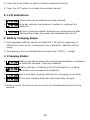
D. In/Out Jacks (see page 7)
1. The system contains Line In, Line Out, and Mic in jacks for connecting external
audio devices.
2. Line In (E1): Pg.7 RCA jacks to connect external audio sources, such as CD/
MP3 players or iPods. The volume of the Line In is controlled solely by the
Master (D1).
3. Line Out (E2): RCA jacks to send the signal to other audio devices, such as
recorders, mixers, or power amps.
4. Mic In (E3): XLR or 1/4” (6.3mm) phone jack for wired microphones. Volume
of this input is controlled by Mic In (D4) and the Master (D1).
E. Speaker Out: (see page 7)
1. Used to connect to an external unpowered speaker (8Ω Min.)
F. Digital Echo System (see page 8)
1. Turn the power switch (H1-1) Pg.8 clockwise to turn on the echo system. Then
use this control to adjust the level of echo in the mix .
2. Adjust the repeat button (H1-2) to select the number of repeats desired.
Adjust the delay button to select the delay time.
3. Mic input jacks (H1-6 and H1-7) are provided for connecting wired Mics. Mic
volume is controlled by H1-4 and H1-5 plus the Master (D-1).
G. Audio Link Transmitter (see page 8)
This module transmits the entire audio mix from one Traveler to another Traveler
equiped with a wireless Mic/Audio Link Receiver.
1. Turn the power switch (H2-7) clockwise to turn on the transmitter.
2. The LCD display (H2-1) will show “On” and the channel in use when the unit
was last turned off.
3. To select a different channel, press the set button (H2-5) and the channel will
flash in the LCD display. Press the up or down button (H2-6) to select the
transmit channel, and then press the set button again to enter the setting. The
LCD will then automatically display the selected channel. To display the
frequency of the selected channel press and hold either the up or down button.
4. Turn the volume control (H2-7) to adjust the audio transmit level. Use this
control in conjunction with the volume controls on the receiving Traveler.

12
5. When transmitting signal, the TX indicator (H2-2) pg. 8 will light Green to
show the transmitting condition. The AF Level indicator lights Yellow (H2-3) to
show a low audio level and lights Red (H2-4) to show high audio level.
6. Set up the receiving Traveler according to the procedure outlined in: A.
Wireless Mic/Audio Link Receiver on page 9. Select the channel chosen
on the transmitting Traveler.
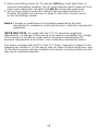
Notice: Changes or modifications not expressly approved by the party
responsible for compliance could void the user's authority to operate the
equipment.
IMPORTANT NOTE: To comply with the FCC RF exposure compliance
requirements, no change to the antenna or the device is permitted. Any change
to the antenna or the device could result in the device exceeding the RF
exposure requirements and void the user's authority to operate the device.
This device complies with Part 15 of the FCC Rules. Operation is subject to the
following two conditions: (1) this device may not cause harmful interference, and
(2) this device must accept any interference received, including interference that
may cause undesired operation.

13
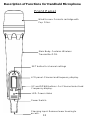
Description of Functions for Handheld Microphone
Wind Screen:
Pop Filter.
Protects cartridge with
Front Panel
Main Body: Contains Wireless
Transmitter PCB.
SET button for channel settings
LCD panel: Channel and frequency display.
UP and DOWN buttons: For Channel select and
Frequency display.
LED: Power status
Power Switch:
Charging Input: Remove lower housing to
access.

14
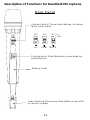
Description of Functions for Handheld Microphone
Rear Panel
HI LOW
MUTE
Volume Control: Three level settings, including
mute, LOW and HI.
Pushing point: Slide the battery cover down by
pressing here.
Battery Cover
Lower Housing: Remove to slide battery cover off or
to connect charger
HI
LOW
HI
LOW
HI
LOW
HI
LOW

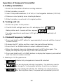
Operation of Handheld Microphone
A. Battery Installation Steps:
1. Turn off the microphone before inserting batteries.
2. Press in the latch to release the lower housing and slide it off.
3. Press in the latch to release the battery cover and slide it down.
4. Insert 2 disposable batteries of 1.5V type or 2 rechargeable batteries of 1.2V
type.
5. Observe proper polarity while inserting batteries.
6. Slide the battery cover back to its original position.
7. Install the lower housing back to the lower part of the microphone.
B. Switch-On Steps:
1. Press the power switch and hold for about two seconds until the LED
turns to RED and "on" is displayed in the LCD.
2. The LCD will then automatically display the selected channel.
:Channel indicator.
:Press and hold the Up or Down button to display the
corresponding frequency
C. Switch Off steps:
1. Press and hold power switch for about two seconds until the LCD displays
OFF.
D. Channel/Frequency Settings (with power on):
1. Press the SET button and hold for about 2 seconds.
2. The Channel number display will start flashing.
3. Press the Up button to display a higher numbered channel.
15

4. Press the Down button to display a lower numbered channel.
5. Press the SET button to activate the selected channel.
E. LCD Indications:
1. :Three bars means batteries are fully charged.
2. :One bar indicates low batteries. Replace or recharge the
batteries.
3. :No bars showing indicates batteries are exhausted and after
flashing three times the power will automatically shut off.
F. Battery Charging Steps:
1. Rechargeable batteries need to be NiMH AA 1.2V with an amperage of
2100mAH or less as the charging function is limited to batteries of that
rating.
2. Recharging is best accomplished by using the AS-TV8DCC charger
3. Charging status:
a. Battery indicator flashing: Non-Rechargeable batteries installed or
no batteries installed. Check the batteries.
b. Battery indicator is flashing and LCD backlight is on: Failing,
corroded, or over-temperature batteries.
c. One or two bars showing: Batteries are charging successfully.
d. Three bars showing: Batteries have been fully charged.
* Please note the microphone will be turned off automatically while it is being
charged.
16

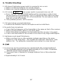
G. Trouble Shooting:
1. LED doesn't light when power switch is pressed to turn on mic.
a. Make sure that the batteries are not discharged.
b. Make sure that the batteries are installed correctly.
2. LCD shows when power switch is pressed to turn mic off.
a. Press the SET, UP and DOWN buttons at the same time in order to turn
the microphone off automatically. The LCD display will flash about ten times
and then the microphone will turn off automatically. The microphone should
now turn on and off normally.
b. If the problem persists, call for service.
3. LCD panel shows unusual indications.
a. Remove the batteries from the microphone and re-install them.
4. No audio from microphone.
a. Check that the frequency of the transmitter is the same as that of the receiver.
b. Make sure that the Mic switch is not set to Mute.
c. Check if the distance between the transmitter and the receiver is too great.
d. Check if the transmitter or the receiver is too close to any large metal objects.
5. Interference and signal Disturbance.
a. Make sure there are no other wireless systems operating on the same
frequency in the same area. This includes Microphones, televisions, radio
stations, etc. Try setting the transmitter and receiver to a new channel.
H. Q&A
1. Q: How long can the microphone be operated with fully charged batteries?
A: Re-chargeable batteries will last approximately 8 to 10 hours. Disposable
batteries will last approximately 13 hours.
Q: How much time is required to recharge batteries from a fully exhausted
state.?
A: Approximately 4 to 5 hours.
17

(14)
(13)
(12)
(11)
(10)
(9)
(8)
(7)
(6)
(1)
(2)
(3)
(4)
(5)
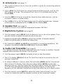
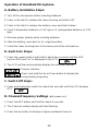
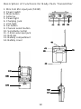
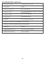
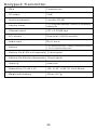
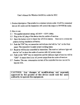
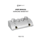
Description of Functions for Body Pack Transmitter
1. Mini XLR Mic input jack (TA3M)
2. Power switch
3. Mute button
4. Antenna
5. Power light
6. Charging Jack
7. LCD light
8. Set button
9. Channel select button
10. Sensitivity control
11. 3.5mm aux input jack
12. Belt clip
13. Battery compartment
14. Battery cover
18
Page is loading ...
Page is loading ...
Page is loading ...
Page is loading ...
Page is loading ...
Page is loading ...
Page is loading ...
Page is loading ...
Page is loading ...
Page is loading ...
Page is loading ...
Page is loading ...
-
 1
1
-
 2
2
-
 3
3
-
 4
4
-
 5
5
-
 6
6
-
 7
7
-
 8
8
-
 9
9
-
 10
10
-
 11
11
-
 12
12
-
 13
13
-
 14
14
-
 15
15
-
 16
16
-
 17
17
-
 18
18
-
 19
19
-
 20
20
-
 21
21
-
 22
22
-
 23
23
-
 24
24
-
 25
25
-
 26
26
-
 27
27
-
 28
28
-
 29
29
-
 30
30
-
 31
31
-
 32
32


Traveler Any Spot Traveler AS-TV8 User manual
- Category
- Soundbar speakers
- Type
- User manual
- This manual is also suitable for
Ask a question and I''ll find the answer in the document
Finding information in a document is now easier with AI
Other documents
-
Rockville RWM1203VS Owner's manual
-
 Jasco Products NHS-PT456 User manual
-
 Jasco Products NHS-TX01A User manual
-
 Powertech Industrial NHSPT-458 User manual
-
Pyle PDWM96 User manual
-
PYLE Audio PDWM94 User manual
-
-
 PYLE Audio PDWM100 User manual
-
Pyle PDMW410BP User manual
-
 qtxsound 103.112 User manual


