Page is loading ...

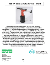
This newly designed light-duty air/hydraulic riveter is ergonomically
designed with the professional in mind. The light weight 2.9 lbs.
well balanced MP-3V includes a Vacuum System and is designed
to maximize a 3/4” stroke and 1,800 lbs. of pulling force along with
a 3 jaw setup that gets the job done. The air supply can be
connected directly or you can use the supplied air connection with
the attached hose for operator convenience. Each tool is supplied
with nosepieces to set 3/32”- 3/16” rivets in all alloys, adjustment
service wrenches, hydraulic fluid, fluid applicator, spare jaws and a
removable swivel air connection line with an air off/on valve built in.
The adjustable Vacuum System control located inside the mandrel
collection bottle allows you to control the force of the air needed to
hold the rivet in place or you may operate with the vacuum system
turned off. Recommended air pressure is 60-95 PSI.
MP-3V Light Duty Riveter / 39045
LA-532
Alcoa Fastening Systems
1925 N MacArthur Dr
Suite 200
Tracy, CA 95376

ADDITION OF HYDRAULIC
Use only compressed air. Check airline for damage from humidity &
contaminants. In order to protect the tool from premature wear, we recommend
the use of a filter, lubricator & regulator. Air connection size ¼” NPT.
WARNING:
Do not use air supply greater than recommended
or tool may be damaged or burst.
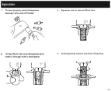
NORMAL OPERATION
1. Connect the air supply then switch
ON/OFF valve to ON position.
2. To turn on and adjust the Vacuum
system remove mandrel nail container
and rotate bar counter-clockwise
Adjust the amount of suction the
vacuum system needs to hold the rivet
in place and to eject spent mandrel
into collection cup. Replace nail
container.
If you don’t want to use vacuum
WARNING: ALWAYS WEAR SAFETY GLASSES
WHEN OPERATING AND PERFORMING MAINTENANCE ON TOOL

system you can turn the vacuum system clockwise to shut it off. The tool will
still be able to set rivets, but it must be tilted backwards to allow spent mandrel
to fall into nail container.
ADDITION OF HYDRAULIC FLUID
Tool is shipped with oil. If it becomes necessary to add oil, follow this procedure.
Please use the supplied priming pump as shown (fig. 4)
1.Disconnect air supply to tool and
switch ON/OFF valve to OFF position.
2.Remove seal screw and seal (see Fig. 3)
3. Screw the priming pump of filled oil into the
bleed screw hole. Actuate the priming pump by
pressing down and releasing several times until
resistance is felt. (Fig. 4)
4. Remove the priming pump and the excessive oil
will flow out. Wipe away and clean out the
excessive oil and replace the seal and screw.
IMPORTANT: Use only Anti-Foam Hydraulic Fluid
WARNING: ALWAYS WEAR SAFETY GLASSES
WHEN OPERATING AND PERFORMING MAINTENANCE ON TOOL

CHANGING NOSEPIECES
1. After selecting the correct size nosepiece for the rivet being used Connect tool to
air supply and pull trigger and hold trigger button.
2. Using wrench (supplied), unscrew nosepiece from frame head & replace with
proper size nosepiece. Tighten down with wrench. DO NOT OVERTIGHTEN.
Release trigger.
Your tool is now ready to work. Insert rivet mandrel into nosepiece. Insert rivet into
predrilled hole in application and pull trigger button and hold until rivet sets then release
the trigger. A second pull may be required.
CLEANING & CHANGING OF JAWS
With use, the jaws of the tool may become dirty or worn. This will cause slipping of the
rivet mandrel & and improper setting of the rivet. To clean the jaws follow this
procedure.
1. Disconnect air supply.
2. Use a suitable wrench, unscrew frame head and remove.
3. Using a pair of wrenches, disassemble front jaw case from rear jaw case.
DO NOT MOVE rear jaw case as this will affect tool operation.
4. To clean jaws, use a stiff dry wire brush.
5. If excessive wear is apparent, replace with new jaws.
6. Reassemble the jaw case assembly.
WARNING: ALWAYS WEAR SAFETY GLASSES
WHEN OPERATING AND PERFORMING MAINTENANCE ON TOOL

IF further maintenance is beyond the scope of this direction sheet and the tool fails to function properly,
contact the factory or return it to the factory for service. Contact our Tool Repair Center at 317-704-8874
for further information.
LIMITED TOOL WARRANTY
Alcoa Fastening Systems - Marson division warrants that this tool will be free from defects in material and workmanship under
normal service and for ninety (90) days from the date of purchase. This warranty applies to the purchaser of the tool for original use
only. All other warranties, whether expressed or implied, including any warranties of merchantability or fitness for purpose are
hereby excluded.
Should this tool fail during this ninety (90) day period, and no unauthorized repairs have been made, return the tool freight prepaid
to the factory for free of charge replacement of any part or parts found by Alcoa Fastening System - Marson division to be defective
due to faulty material or workmanship. This represents the sole obligation of Alcoa Fastening Systems - Marson under this warranty.
In no event shall Alcoa Fastening Systems - Marson division be liable for any consequential or special damages arising from the
purchase or use of this tool. You may have other rights which vary from state to state.

Part
Number
AFS Part No.
Description
Part
Number
AFS Part No.
Description
Part
Number
AFS Part No.
Description
1
M95200
3/32" NOSEPIECE
1
M95201
1/8" NOSEPIECE
1
M95202
5/32" NOSEPIECE
1
M95203
3/16" NOSEPIECE
2
M95204
O-RING 7x1
3
M95205
NOSEPIECE CASING
4
M95206
JAW CARRIER
5
M95207
JAWS (1set=3pcs)
6
M95208
PUSHER
7
M95209
JAW PUSHER SPRING
8
M95210
JAW HOUSING
9
M95211
LOCK RING
10
M95212
O-RING 12x2.4
11
M95213
TEFLON RING 12x1.4
12
M95214
HEAD ASSEMBLY
13
M95215
O-RING 20x3.5
14
M95216
TEFLON RING 20x1.4
15
M95217
PRINCIPAL AXIS UNIT
16
M95218
RESTORE SPRING
17
M95219
O-RING 7x2
18
M95220
VACUUM VALVE ASSEMBLY
19
M95221
O-RING 16x2.4
20
M95222
O-RING 27.2x1.9
21
M95223
AIRPROOF LID
22
M95224
O-RING 31.5x3.1
23
M95225
PARTITION
24
M95226
SILENCER
25
M95227
NAIL CONTAINER
26
M95228
REAR COVER
27
M95229
O-RING 8x2
28
M95230
WASHER
29
M95231
SCREW 5x8
30
M95232
HANDLE(LEFT)
31
M95233
HANDLE(RIGHT)
32
M95234
TRIGGER
33
M95235
TRIGGER VALVE
34
M95236
ON/OFF BASE
35
M95237
O-RING 3.7x1
Part
Number
AFS Part No.
Description
36
M95238
AIR INTERFACE
37
M95239
TIE RING
38
M95240
AIR TUBE
39
M95241
TAPPING SCREW
40
M95242
AIR VALVE BODY
41
M95243
AIR VALVE RING
42
M95244
O-RING 9.5x12.5x1.5
43
M95245
AIR VALVE BASE
44
M95246
SUBORDINATE TUBE
45
M95247
O-RING 11.5x14.5x1.5
46
M95248
CONNECTING BASE
47
M95249
O-RING 9.2x2.4
48
M95250
ON/OFF ASSEMBLY
49
M95251
AIR VALVE ROD
50
M95252
SCREW PLUG
51
M95253
SILENCER
52
M95254
CYLINDER COVER
53
M95255
O-RING 66x2
54
M95256
BOLT 3x6
55
M95257
ROCK NUT
56
M95258
BUFFER
57
M95259
LIP SEAL 8x14x6
58
M95260
AIR TUBE PISTON
59
M95261
O-RING 11.6x1.5
60
M95262
PISTON RING
61
M95263
TRANSFER TUBE
62
M95264
PISTON ROD
63
M95265
CYLINDER PISTON
64
M95266
O-RING 75x86x5.7
65
M95267
EL 8x14.2x5
66
M95268
BOLT 6x10
67
M95269
CYLINDER
68
M95270
BASE COVER
69
M95271
BS 5.7x10x1
70
M95272
SEAL SCREW 5x6
71
M95273
HOOK
/