Bauknecht DKE 1360 AL Program Chart
- Category
- Cooker hoods
- Type
- Program Chart
This manual is also suitable for

5019 418 33032
DKE 1390 - DKE 1360 - DKEL 1760
INSTALLATIONSANGABEN
Mindestabstand zur Kochfläche: 60 cm (Elektroplatten), 75 cm (Gas-, Öl-
oder Kohleflammen). Folgen Sie bei der Installation der Nummerierung
(1
Ö
2
Ö
3
Ö
.....). Schließen Sie das Gerät erst nach erfolgter Installation an
die Stromversorgung an.
INSTALLATION SHEET
Minimum height above cooker: 60cm (electric cookers), 75cm (gas, gas oil
or coal cookers). To install follow points (1
Ö
2
Ö
3
Ö
.....). Do not connect the
appliance to the electrical power supply until installation is completed.
FICHE D'INSTALLATION
Distance minimale par rapport à la cuisinière : 60 cm (cuisinière
électrique), 75 cm (cuisinière à gaz, mazout ou charbon). Pour le montage,
suivez la numérotation (1
Ö
2
Ö
3
Ö
.....). Ne branchez pas l'appareil tant que
l'installation n'est pas terminée.
INSTALLATIEKAART
Minimumafstand tot het kooktoestel: 60cm (elektrische kooktoestellen),
75cm (kooktoestellen op gas, olie of kolen). Volg voor de montage de
nummering (1
Ö
2
Ö
3
Ö
.....). Geef het apparaat geen stroom totdat de
installatie geheel voltooid is.
FICHA DE INSTALACIÓN
Distancia mínima desde los quemadores: 60 cm (fuegos eléctricos), 75 cm
(fuegos de gas, gasóleo o carbón). Para el montaje, siga la numeración
(1
Ö
2
Ö
3
Ö
...). No enchufe el aparato hasta que su instalación no esté
terminada.
FICHA DE INSTALAÇÃO
Distância mínima dos fogões: 60 cm (fogões eléctricos), 75 cm (fogões a
gás, óleo ou carbono). Para montar siga a numeração (1
Ö
2
Ö
3
Ö
.....). Não
ligue o aparelho à corrente eléctrica até a instalação estar concluída.
SCHEDA INSTALLAZIONE
Distanza minima dai fuochi: 60cm (fuochi elettrici), 75cm (fuochi a gas,
gasolio o carbone). Per il montaggio seguire la numerazione (1
Ö
2
Ö
3
Ö
.....).
Non dare corrente all’apparecchio finchè l’installazione non è totalmente
completata.
ùüùü+ùùùþ
ü$12.)12.1.)2"0120"FP02!"0120"FP0120"
.0! #02!0. #0! # +.22 21. #1202
.!1
Ö
Ö
Ö
2! 3 / 2020002!)!0*.21#10#!
2 !&12"0.212.1"
D
GB
F
NL
E
P
I
GR
41833032.fm Page 1 Friday, October 24, 2003 10:06 AM

5019 418 33032
DKE 1390 - DKE 1360 - DKEL 1760
R
T
Y
Y
Y
Y
R
T
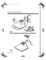
!
S
U
1
2
V
Z
W
41833032.fm Page 2 Friday, October 24, 2003 10:06 AM

5019 418 33032
DKE 1390 - DKE 1360 - DKEL 1760
V
X
Z
F
J
D
G
P
M
L
3
4
41833032.fm Page 3 Friday, October 24, 2003 10:06 AM

5019 418 33032
DKE 1390 - DKE 1360 - DKEL 1760
Assembly - fig. 1-2-3-4
•
In order to facilitate installation of the hood and flue support, trace a centre line on the wall
between the hob and ceiling (
Z
).
•
Position the template against the wall, then mark and drill the holes where indicated (
Y
).
•
Insert two wall plugs with hooks (
V
).
•
Hang the hood and adjust the position by turning the adjustment screws (
S
).
•
Remove the grease filters and mark the holes for secure fixing (
T-R
).
•
Remove the hood and drill the holes (4 x Ø 8 mm).
•
Insert 4 wall plugs and two screws in the top holes: they will ensure secure fixing (
X
).
•
Fix the flue support (
Z
) as close as possible to the ceiling with two screws and wall plugs.
Important! Check that the support is perfectly aligned with the hood.
•
Rehang the hood on the wall.
•
Fix the hood with two screws at the bottom (
D
).
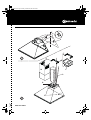
Installing the exhaust pipe (Extractor version)
Warning! The exhaust pipe and clamps are not supplied and must be bought separately.
•
Connect one end of the exhaust pipe (
J
) to the hood (
G
) with the other end directed to the
outside.
Installing the deflector (Filter version)
•
Fix the deflector (
F
) to the flue support with 4 screws.
•
Connect the deflector to the hood with an exhaust pipe.
Warning! The exhaust pipe and clamps are not supplied and must be bought separately.
Installing the telescopic flue
•
Connect the hood to the power supply.
•
Fix the telescopic flue (
M
) to the support (
Z
) with two screws and let it slide down to its
specific seat on the top of the hood.
D F NL E
GB
P I GR
41833032.fm Page 7 Friday, October 24, 2003 10:06 AM

5019 418 33032
DKE 1390 - DKE 1360 - DKEL 1760
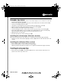
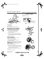
1.
Control panel
2.
Grease filters
3.
Lighting unit
4.
Telescopic flue
5.
Grease filter release-replace handle
Removing and renewing or
washing the grease filter
1.
Disconnect the electrical power supply.
2.
Remove the grease filters (
Fig. 5
):
a
- push the handles backwards
b
- then downwards.
3.
After the grease filter has been replaced or
cleaned (depending on model), refit the parts in
reverse order, making sure the entire extraction
surface is covered.
Replacing bulbs
1.
Disconnect the electrical power supply.
2.
Remove the grease filters.
3.
Remove the burnt-out bulb.
Replace using 40W max (E14) bulbs only.
4.
Refit the lighting unit.
Fitting or renewing the carbon
filter - Fig. 6:
1.
Disconnect the electrical power supply.
2.
Remove the grease filters.
3.
If the filters are not already fitted, locate one on
each side to cover both motor protection grilles,
check that pins
R
on the duct align with slots
S
,
then turn it clockwise until it locks.
4.
To remove the carbon filter, proceed in reverse
order.
5.
Replace the grease filters.
CONTROL PANEL
A.
Light switch.
B.
Speed selector switch.
Fig. 5
4
2
3
3
1
OI O123i
A
B
a
b
Fig. 8
Very large amount of
steam and fumes
(only model DKEL 1760)
R
R
S
S
Fig. 7
Small amount
of steam and fumes
Medium amount of
steam and fumes
Large amount of steam and
fumes
Fig. 6
D F NL E
GB
P I GR
PRODUCT DESCRIPTION SHEET
41833032.fm Page 8 Friday, October 24, 2003 10:06 AM
-
 1
1
-
 2
2
-
 3
3
-
 4
4
-
 5
5


Bauknecht DKE 1360 AL Program Chart
- Category
- Cooker hoods
- Type
- Program Chart
- This manual is also suitable for
Ask a question and I''ll find the answer in the document
Finding information in a document is now easier with AI
Related papers
-
Bauknecht DKE 1360 IN Program Chart
-
Bauknecht DKEL 3860 IN Program Chart
-
Bauknecht DKLC 3710 IN Program Chart
-
Whirlpool DNHV 5363 SG User guide
-
-
Bauknecht DKEL 5790 IN Program Chart
-
-
Whirlpool DDB 5390 AL User guide
-
Bauknecht DE 5363 SG Program Chart
-
Other documents
-
Faro 63520 Operating instructions
-
-
-
-
Whirlpool AKR 921 AL Program Chart
-
IKEA HDN SW800 Program Chart
-
-
-
Whirlpool AKR 651 IX Program Chart
-
Whirlpool AKR 643 GY Owner's manual