Asus B85-A User manual
- Category
- Server/workstation motherboards
- Type
- User manual

Motherboard
B85-A

ii
E8695
First Edition V1
Sept. 2013
Copyright © 2013 ASUSTeK COMPUTER INC. All Rights Reserved.
No part of this manual, including the products and software described in it, may be reproduced,
transmitted, transcribed, stored in a retrieval system, or translated into any language in any form or by any
means, except documentation kept by the purchaser for backup purposes, without the express written
permission of ASUSTeK COMPUTER INC. (“ASUS”).
Product warranty or service will not be extended if: (1) the product is repaired, modied or altered, unless
such repair, modication of alteration is authorized in writing by ASUS; or (2) the serial number of the
product is defaced or missing.
ASUS PROVIDES THIS MANUAL “AS IS” WITHOUT WARRANTY OF ANY KIND, EITHER EXPRESS
OR IMPLIED, INCLUDING BUT NOT LIMITED TO THE IMPLIED WARRANTIES OR CONDITIONS OF
MERCHANTABILITY OR FITNESS FOR A PARTICULAR PURPOSE. IN NO EVENT SHALL ASUS, ITS
DIRECTORS, OFFICERS, EMPLOYEES OR AGENTS BE LIABLE FOR ANY INDIRECT, SPECIAL,
INCIDENTAL, OR CONSEQUENTIAL DAMAGES (INCLUDING DAMAGES FOR LOSS OF PROFITS,
LOSS OF BUSINESS, LOSS OF USE OR DATA, INTERRUPTION OF BUSINESS AND THE LIKE),
EVEN IF ASUS HAS BEEN ADVISED OF THE POSSIBILITY OF SUCH DAMAGES ARISING FROM ANY
DEFECT OR ERROR IN THIS MANUAL OR PRODUCT.
SPECIFICATIONS AND INFORMATION CONTAINED IN THIS MANUAL ARE FURNISHED FOR
INFORMATIONAL USE ONLY, AND ARE SUBJECT TO CHANGE AT ANY TIME WITHOUT NOTICE,
AND SHOULD NOT BE CONSTRUED AS A COMMITMENT BY ASUS. ASUS ASSUMES NO
RESPONSIBILITY OR LIABILITY FOR ANY ERRORS OR INACCURACIES THAT MAY APPEAR IN THIS
MANUAL, INCLUDING THE PRODUCTS AND SOFTWARE DESCRIBED IN IT.
Products and corporate names appearing in this manual may or may not be registered trademarks or
copyrights of their respective companies, and are used only for identication or explanation and to the
owners’ benet, without intent to infringe.
Offer to Provide Source Code of Certain Software
This product contains copyrighted software that is licensed under the General Public License (“GPL”),
under the Lesser General Public License Version (“LGPL”) and/or other Free Open Source Software
Licenses. Such software in this product is distributed without any warranty to the extent permitted by the
applicable law. Copies of these licenses are included in this product.
Where the applicable license entitles you to the source code of such software and/or other additional data,
you may obtain it for a period of three years after our last shipment of the product, either
(1) for free by downloading it from http://support.asus.com/download
or
(2) for the cost of reproduction and shipment, which is dependent on the preferred carrier and the location
where you want to have it shipped to, by sending a request to:
ASUSTeK Computer Inc.
Legal Compliance Dept.
15 Li Te Rd.,
Beitou, Taipei 112
Taiwan
In your request please provide the name, model number and version, as stated in the About Box of the
product for which you wish to obtain the corresponding source code and your contact details so that we
can coordinate the terms and cost of shipment with you.
The source code will be distributed WITHOUT ANY WARRANTY and licensed under the same license as
the corresponding binary/object code.
This offer is valid to anyone in receipt of this information.
ASUSTeK is eager to duly provide complete source code as required under various Free Open Source
Software licenses. If however you encounter any problems in obtaining the full corresponding source
code we would be much obliged if you give us a notication to the email address [email protected], stating
the product and describing the problem (please DO NOT send large attachments such as source code
archives, etc. to this email address).

iii
Contents
Safety information ...................................................................................... iv
About this guide ......................................................................................... iv
Package contents ....................................................................................... vi
B85-A specications summary ................................................................. vi
Product introduction
1.1 Before you proceed ..................................................................... 1-1
1.2 Motherboard overview ................................................................. 1-1
1.3 Central Processing Unit (CPU) ................................................... 1-3
1.4 System memory ........................................................................... 1-7
1.5 Expansion slots ............................................................................ 1-9
1.6 Jumpers ...................................................................................... 1-10
1.7 Connectors ................................................................................. 1-11
1.8 Onboard LEDs ............................................................................ 1-19
1.9 Software support ........................................................................ 1-20
BIOS information
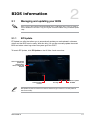
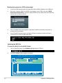
2.1 Managing and updating your BIOS ............................................ 2-1
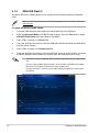
2.2 BIOS setup program .................................................................... 2-6
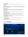
2.3 My Favorites ................................................................................. 2-9
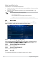
2.4 Main menu .................................................................................. 2-10
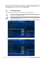
2.5 Ai Tweaker menu ........................................................................ 2-12
2.6 Advanced menu ......................................................................... 2-24
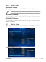
2.7 Monitor menu ............................................................................. 2-33
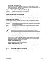
2.8 Boot menu .................................................................................. 2-36
2.9 Tools menu ................................................................................. 2-42
2.10 Exit menu .................................................................................... 2-43
Appendices
Notices .......................................................................................................A-1
ASUS contact information .......................................................................A-3

iv
Safety information
Electrical safety
To prevent electrical shock hazard, disconnect the power cable from the electrical outlet
before relocating the system.
When adding or removing devices to or from the system, ensure that the power cables
for the devices are unplugged before the signal cables are connected. If possible,
disconnect all power cables from the existing system before you add a device.
Before connecting or removing signal cables from the motherboard, ensure that all
power cables are unplugged.
Seek professional assistance before using an adapter or extension cord. These devices
could interrupt the grounding circuit.
Ensure that your power supply is set to the correct voltage in your area. If you are not
sure about the voltage of the electrical outlet you are using, contact your local power
company.
If the power supply is broken, do not try to x it by yourself. Contact a qualied service
technician or your retailer.
Operation safety
Before installing the motherboard and adding components, carefully read all the manuals
that came with the package.
Before using the product, ensure all cables are correctly connected and the power
cables are not damaged. If you detect any damage, contact your dealer immediately.
To avoid short circuits, keep paper clips, screws, and staples away from connectors,
slots, sockets and circuitry.
Avoid dust, humidity, and temperature extremes. Do not place the product in any area
where it may be exposed to moisture.
Place the product on a stable surface.
If you encounter technical problems with the product, contact a qualied service
technician or your retailer.
About this guide
This user guide contains the information you need when installing and conguring the
motherboard.
How this guide is organized
This guide contains the following parts:
• Chapter 1: Product introduction
This chapter describes the features of the motherboard and the new technology it
supports. It includes descriptions of the switches, jumpers, and connectors on the
motherboard.
• Chapter 2: BIOS information
This chapter discusses changing system settings through the BIOS Setup menus.
Detailed descriptions fo the BIOS parameters are also provided.
•
•
•
•
•
•
•
•
•
•
•
•
v
Where to nd more information
Refer to the following sources for additional information and for product and software
updates.
1. ASUS websites
The ASUS website provides updated information on ASUS hardware and software
products. Refer to the ASUS contact information.
2. Optional documentation
Your product package may include optional documentation, such as warranty yers,
that may have been added by your dealer. These documents are not part of the
standard package.
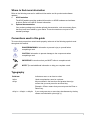
Conventions used in this guide
To ensure that you perform certain tasks properly, take note of the following symbols used
throughout this manual.
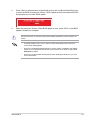
DANGER/WARNING: Information to prevent injury to yourself when
completing a task.
CAUTION: Information to prevent damage to the components when
completing a task
IMPORTANT: Instructions that you MUST follow to complete a task.
NOTE: Tips and additional information to help you complete a task.
Typography
Bold text Indicates a menu or an item to select.
Italics
Used to emphasize a word or a phrase.
<Key> Keys enclosed in the less-than and greater-than sign
means that you must press the enclosed key.
Example: <Enter> means that you must press the Enter or
Return key.
<Key1> + <Key2> + <Key3> If you must press two or more keys simultaneously, the key
names are linked with a plus sign (+).

vi
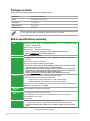
B85-A specications summary
(continued on the next page)
Package contents
Check your motherboard package for the following items.
Motherboard ASUS B85-A motherboard
Cables 2 x Serial ATA 6.0 Gb/s cables
Accessories 1 x I/O Shield
Application DVD Support DVD
Documentation User Guide
If any of the above items is damaged or missing, contact your retailer.
CPU LGA1150 socket for Intel® 4th Generation Core™ i7 / i5 / i3, Pentium®, and
Celeron® processors
Supports Intel® 22nm CPU
Supports Intel® Turbo Boost Technology 2.0
* The Intel® Turbo Boost Technology 2.0 support depends on the CPU types.
** Refer to www.asus.com for Intel® CPU support list.
Chipset Intel® B85 Express Chipset
Memory 4 x DIMM, max. 32GB, DDR3 1600 / 1333 / 1066 MHz, non-ECC, un-buffered
memory
Dual-channel memory architecture
Supports Intel® Extreme Memory Prole (XMP)
* Due to Intel® chipsest limitation, DDR3 1600MHz and higher memory modules on XMP
mode will run at the maximum transfer rate of DDR3 1600MHz.
** When you install a total memory of 4GB capacity or more, Windows® 32-bit operating
system may only recognize less than 3GB. We recommend a maximum of 3GB system
memory if you are using a Windows® 32-bit operating system.
*** Refer to www.asus.com for the latest Memory QVL (Qualied Vendors List).
Graphics Integrated graphics processor - Intel® HD Graphics support
Multi-VGA output support: DVI-D and RGB ports
- Supports DVI-D with max.resolution of 1920 x 1200 @60Hz
- Supports RGB with max. resolution of 1920 x 1200 @60Hz
Supports Intel® InTruTM 3D/Quick Sync Video/Clear Video HD Technology/InsiderTM
Maximum shared memory of 1024MB
Multi-GPU
Support Supports AMD® CrossFireXTM technology
Expansion
slots
1 x PCI Express 3.0/2.0 x16 slot (@ x16)
1 x PCI Express 2.0 x16 slot (@ x4, compatible with PCIe x4, x1 devices)
2 x PCI Express 2.0 x1 slots
3 x PCI slots
Audio Realtek® ALC887 8-channel High Denition Audio CODEC
- Supports jack-detection, multi-streaming and front panel jack-retasking
* Use a chassis with HD audio module in the front panel to support an 8-channel audio
output.

vii
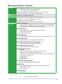
B85-A specications summary
(continued on the next page)
Storage Intel® B85 Express Chipset:
- 2 x Serial ATA 3.0 Gb/s connectors (dark brown)
- 4 x Serial ATA 6.0 Gb/s connector (yellow)
Supports Intel® Rapid Start Technology, Intel® Smart Connect Technology*
* These functions will work depending on the CPU installed.
LAN Realtek® 8111G Gigabit LAN controller
USB Intel® B85 Express Chipset - supports ASUS USB 3.0 Boost
2 x USB 3.0/2.0 ports at midboard for front panel support
2 x USB 3.0/2.0 ports at rear panel (blue)
8 x USB 2.0 ports (4 ports at midboard, 4 ports at back panel)
ASUS unique
features
ASUS 5X Protection
- ASUS motherboards safeguard your PC with 5X Protection: DIGI+VRM, DRAM
Fuse, ESD Guards, High-quality 5K-Hour Solid Capacitors, and Stainless Steel
Back I/O to ensure the best quality, reliability, and durability
ASUS Dig+VRM
- ASUS Digital Power Control: Digital Power Design for CPU
- ASUS 4 Phase Power Design
- ASUS CPU power utility
ASUS DRAM Fuse
- Enhanced DRAM overcurrent protection and short circuit damage prevention
ASUS ESD Guards
- Strong ESD protection for extended component lifespan
ASUS High-quality 5K-Hour Solid Capacitors
- 2.5x Long Lifespan with excellent durability
ASUS Stainless Steel Back I/O
- 3x More durable corrosion-resistant coating
ASUS Exclusive Features:
- ASUS EPU
- ASUS USB 3.0 Boost featuring speedy USB 3.0 transmission
- ASUS Disk Unlocker featuring 3TB+ HDD support
- ASUS Network iControl featuring instant network network bandwidth domination
for top network program in use
- ASUS GPU Boost
- ASUS AI Suite 3
- ASUS Anti Surge
ASUS Quiet Thermal Solution:
- ASUS Fanless Design: stylish heatsink solution
ASUS EZ DIY:
- ASUS UEFI BIOS EZ Mode featuring friendly graphical user interface
- ASUS CrashFree BIOS 3
- ASUS EZ Flash 2
ASUS Q-Design
- ASUS Q-Slot

viii
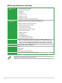
B85-A specications summary
Specications are subject to change without notice.
Back Panel I/O
ports
1 x PS/2 keyboard port (purple)
1 x PS/2 mouse port (green)
1 x DVI-D port
1 x RGB port
1 x LAN (RJ-45) port
4 x USB 2.0/1.1 ports
2 x USB 3.0/2.0 ports
3 x Audio jacks support 8-channel audio output
Internal
connectors
1 x USB 3.0 connector supports additional 2 USB 3.0 ports
2 x USB 2.0 connectors support additional 4 USB 2.0 ports
2 x SATA 3.0 Gb/s connectors (dark brown)
4 x SATA 6.0 Gb/s connector (yellow)
1 x 4-pin CPU fan connector
1 x 4-pin Chassis fan connector
1 x Front panel audio connector (AAFP)
1 x System panel connector
1 x S/PDIF connector
1 x COM Header
1 x Clear CMOS jumper
1 x 24-pin EATX power connector
1 x 8-pin ATX 12V power connector
BIOS features 64 Mb Flash ROM, UEFI AMI BIOS, PnP, DMI v2.0, WfM2.0, SM BIOS v2.7,
ACPI v4.0a, Multi-language BIOS, ASUS EZ Flash 2, ASUS CrashFree BIOS
3, My Favorites, Quick Note, Last Modied log, F12 PrintScreen, F3 Shortcut
function, and ASUS DRAM SPD (Serial Presence Detect) memory information
Manageability Wfm 2.0, DMI 2.0, WOL by PME, PXE
Support DVD Drivers
ASUS utilities
EZ Update
Anti-virus software (OEM version)
Form factor ATX form factor: 12.0”x 8.2” (30.5cm x 20.8cm)

ASUS B85-A 1-1
Product introduction
1
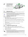
1.1 Before you proceed
Take note of the following precautions before you install motherboard components or change
any motherboard settings.
• Unplug the power cord from the wall socket before touching any component.
• Before handling components, use a grounded wrist strap or touch a safely grounded
object or a metal object, such as the power supply case, to avoid damaging them due
to static electricity.
• Hold components by the edges to avoid touching the ICs on them.
• Whenever you uninstall any component, place it on a grounded antistatic pad or in the
bag that came with the component.
• Before you install or remove any component, ensure that the ATX power supply is
switched off or the power cord is detached from the power supply. Failure to do so
may cause severe damage to the motherboard, peripherals, or components.
1.2 Motherboard overview
Before you install the motherboard, study the conguration of your chassis to ensure that the
motherboard ts.
Unplug the power cord before installing or removing the motherboard. Failure to do so can
cause you physical injury and damage to motherboard components.
1.2.1 Placement direction
When installing the motherboard, place it into the chassis in the correct orientation. The edge
with external ports goes to the rear part of the chassis as indicated in the image.
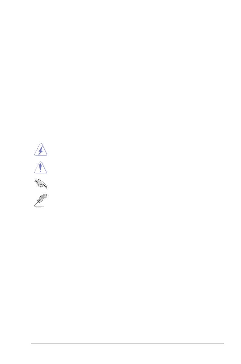
1.2.2 Screw holes
Place six screws into the holes indicated by circles to secure the motherboard to the chassis.
Do not overtighten the screws! Doing so can damage the motherboard.
1-2 Chapter 1: Product introduction
B85-A
Place this side
towards the rear
of the chassis
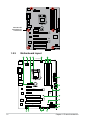
1.2.3 Motherboard layout
B85-A
PCIEX16_1
PCIEX16_2
PCIEX1_1
PCIEX1_2
ASM
1083
PCI1
PCI2
PCI3
USB1112 USB1314
AAFP
EATXPWR
CPU_FAN
BATTERY
Super
I/O
Realtek
ALC887
RTL
8111G
KBMS
DVI_VGA
64Mb
BIOS
SB_PWR
CLRTC
20.8cm(8.2in)
Intel®
B85
DDR3 DIMM_A1 (64bit, 240-pin module)
DDR3 DIMM_A2 (64bit, 240-pin module)
DDR3 DIMM_B1 (64bit, 240-pin module)
DDR3 DIMM_B2 (64bit, 240-pin module)
SATA6G_3SATA6G_4
PANEL
SATA_5
SATA6G_1SATA6G_2
SATA_6
AUDIO
LAN_USB34
USB3_56
USB910
CHA_FAN1
SPDIF_OUT
30.5cm(12.0in)
LGA1150
DIGI
+VRM
COM
EATX12V
USB3_12
32 31 4 5
10
13 11
12
2
8
7
6
9
6
14

ASUS B85-A 1-3
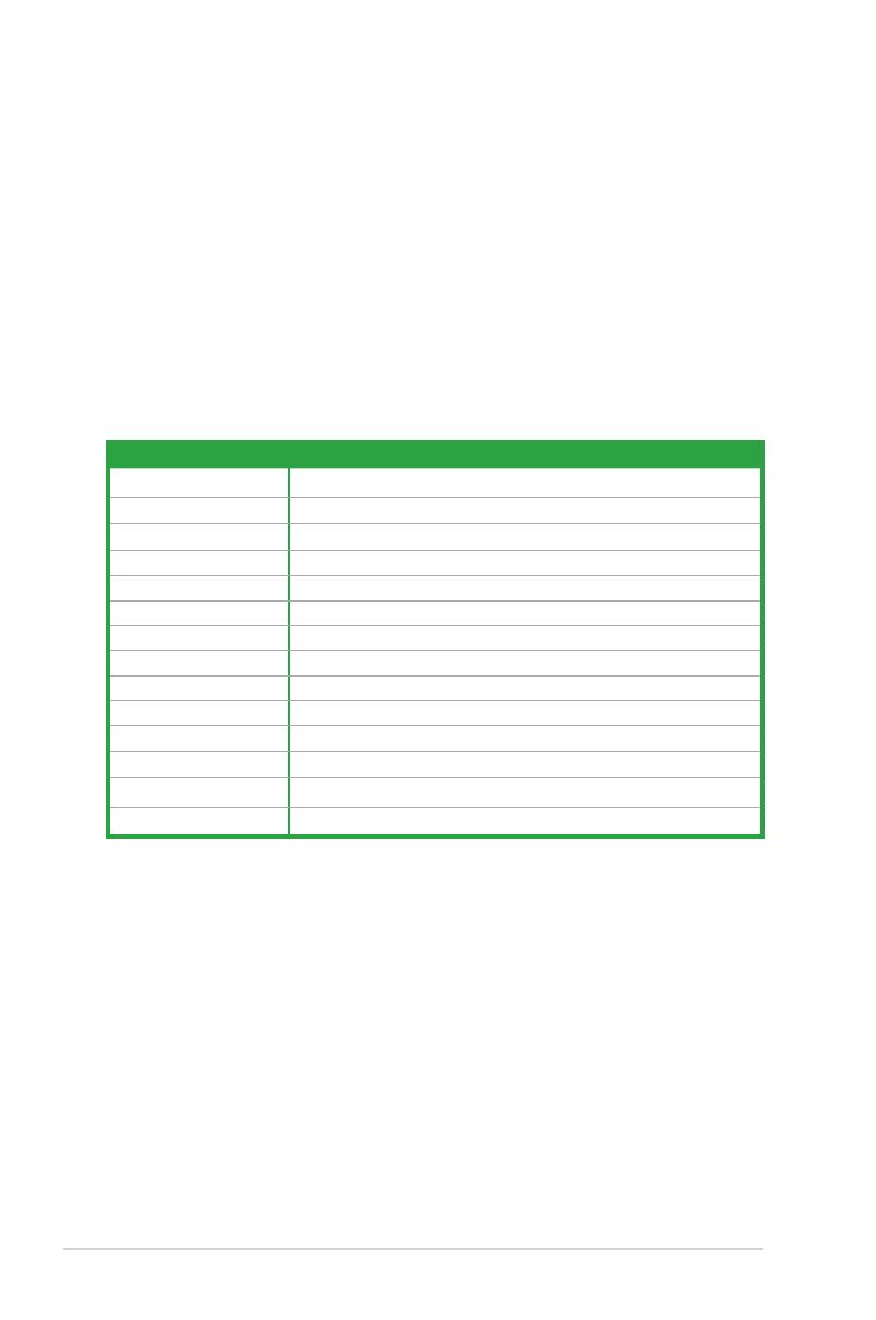
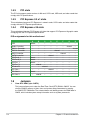
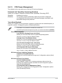
1.2.4 Layout contents
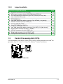
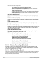
1.3 Central Processing Unit (CPU)
This motherboard comes with a surface mount LGA1150 socket designed for the Intel® 4th
generation Core™ i7 / Core™ i5 / Core™ i3, Pentium® , Celeron® processors.
B85-A
B85-A CPU socket LGA1150
Connectors/Jumpers/Slots/LED Page
1. Serial port connectors (10-1 pin COM) 1-13
2. ATX power connectors (24-pin EATXPWR, 8-pin EATX12V) 1-14
3. CPU and chassis fan connectors (4-pin CPU_FAN, 4-pin CHA_FAN) 1-16
4. Intel® LGA1150 CPU socket 1-3
5. DDR3 DIMM slots 1-7
6. Intel® B85 Serial ATA 6.0Gb/s connector (7-pin SATA6G_1~4 [yellow]) 1-17
7. USB 3.0 connector (20-1 pin USB3_12) 1-16
8. Onboard LED (SB_PWR) 1-19
9. Clear RTC RAM (3-pin CLRTC) ) 1-10
10. Intel® B85 Serial ATA 3.0Gb/s connectors (7-pin SATA_5~6 [dark brown]) 1-17
11. System panel connector (20-8 pin F_PANEL) 1-18
12. USB 2.0 connectors (10-1 pin USB11~14) 1-15
13. Digital audio connector (4-1 pin SPDIF_OUT) 1-14
14. Front panel audio connector (10-1 pin AAFP) 1-15
1-4 Chapter 1: Product introduction
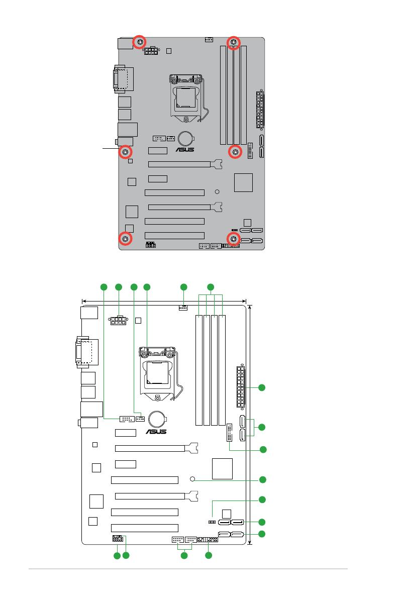
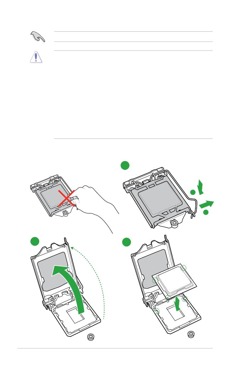
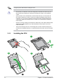
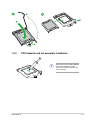
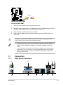
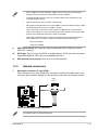
1.3.1 Installing the CPU
1
23
A
B
Unplug all power cables before installing the CPU.
• Ensure that you install the correct CPU designed for the LGA1150 socket only. DO
NOT install a CPU designed for LGA1155 and LGA1156 sockets on the LGA1150
socket.
• Upon purchase of the motherboard, ensure that the PnP cap is on the socket and
the socket contacts are not bent. Contact your retailer immediately if the PnP cap
is missing, or if you see any damage to the PnP cap/socket contacts/motherboard
components. ASUS will shoulder the cost of repair only if the damage is shipment/
transit-related.
• Keep the cap after installing the motherboard. ASUS will process Return Merchandise
Authorization (RMA) requests only if the motherboard comes with the cap on the
LGA1150 socket.
• The product warranty does not cover damage to the socket contacts resulting from
incorrect CPU installation/removal, or misplacement/loss/incorrect removal of the PnP
cap.

ASUS B85-A 1-5
A
B
C
5
4
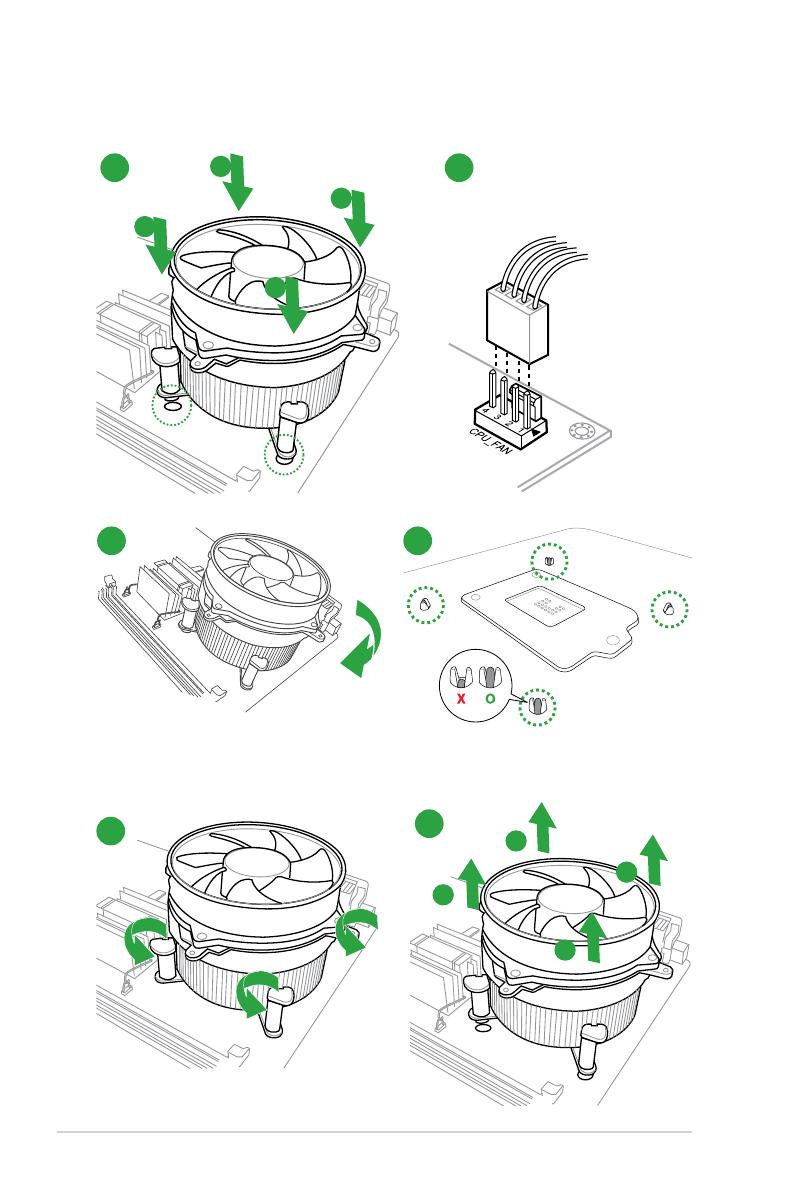
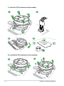
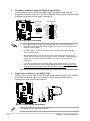
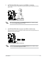
1.3.2 CPU heatsink and fan assembly installation
Apply the Thermal Interface Material
to the CPU heatsink and CPU
before you install the heatsink and
fan if necessary.
1-6 Chapter 1: Product introduction
3 4
A
B
B
A
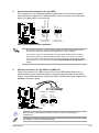
To uninstall the CPU heatsink and fan assembly
2
1
To install the CPU heatsink and fan assembly
2
B
A
A
B
1
ASUS B85-A 1-7
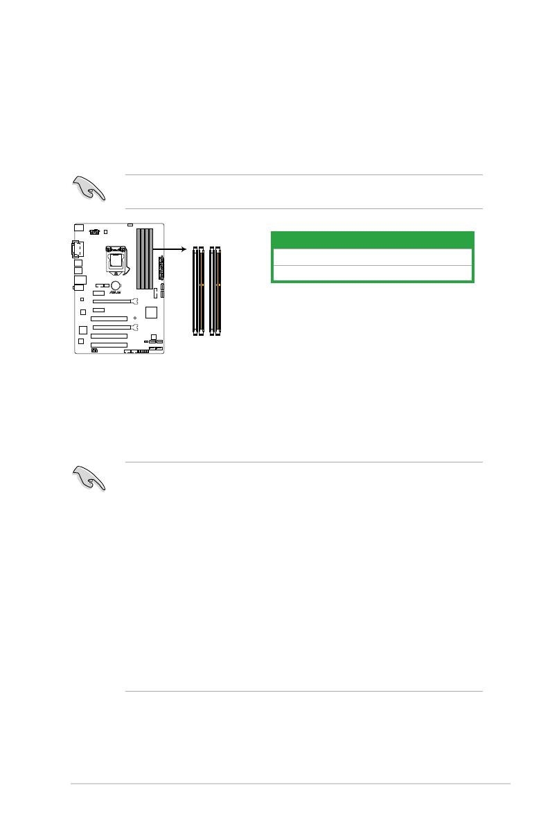
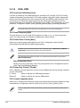
1.4 System memory
1.4.1 Overview
This motherboard comes with four Double Data Rate 3 (DDR3) Dual Inline Memory Module
(DIMM) sockets. A DDR3 module is notched differently from a DDR or DDR2 module. DO
NOT install a DDR or DDR2 memory module to the DDR3 slot.
According to Intel® CPU spec, DIMM voltage below 1.65V is recommended to protect the
CPU.
Channel Sockets
Channel A DIMM_A1 & DIMM_A2
Channel B DIMM_B1 & DIMM_B2
B85-A
B85-A 240-pin DDR3 DIMM sockets
DIMM_A1
DIMM_A2
DIMM_B1
DIMM_B2
1.4.2 Memory congurations
You may install 1GB, 2GB, 4GB, and 8GB unbuffered non-ECC DDR3 DIMMs into the DIMM
sockets.
• You may install varying memory sizes in Channel A and Channel B. The system maps
the total size of the lower-sized channel for the dual-channel conguration. Any excess
memory from the higher-sized channel is then mapped for single-channel operation.
• Due to Intel® chipset limitation, DDR3 1600MHz and higher memory modules on XMP
mode will run at the maximum transfer rate of DDR3 1600MHz.
• Always install DIMMs with the same CAS latency. For optimal compatibility, we
recommend that you install memory modules of the same version or date code (D/C)
from the same vendor. Check with the retailer to get the correct memory modules.
• Due to the memory address limitation on 32-bit Windows® OS, when you install 4GB
or more memory on the motherboard, the actual usable memory for the OS can be
about 3GB or less. For effective use of memory, we recommend that you do any of the
following:
- Use a maximum of 3GB system memory if you are using a 32-bit Windows® OS.
- Install a 64-bit Windows® OS if you want to install 4GB or more on the
motherboard.
• This motherboard does not support DIMMs made up of 512Mb (64MB) chips or less.

1-8 Chapter 1: Product introduction
• The default memory operation frequency is dependent on its Serial Presence Detect
(SPD), which is the standard way of accessing information from a memory module.
• For system stability, use a more efcient memory cooling system to support a full
memory load (4 DIMMs).
• Visit the ASUS website at: www.asus.com for the latest QVL.
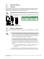
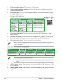
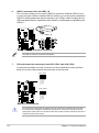
1.4.3 Installing a DIMM
Unplug the power supply before adding or removing DIMMs or other system components.
Failure to do so can cause severe damage to both the motherboard and the components.
1. Press the retaining clips
outward to unlock a
DIMM socket.
2. Align a DIMM on the
socket such that the
notch on the DIMM
matches the DIMM slot
key on the socket.
A DIMM is keyed with a notch so that it ts in only one direction. DO NOT force a DIMM into
a socket in the wrong direction to avoid damaging the DIMM.
3. Firmly insert the DIMM into the
socket until the retaining clips snap
back in place and the DIMM is
properly seated.
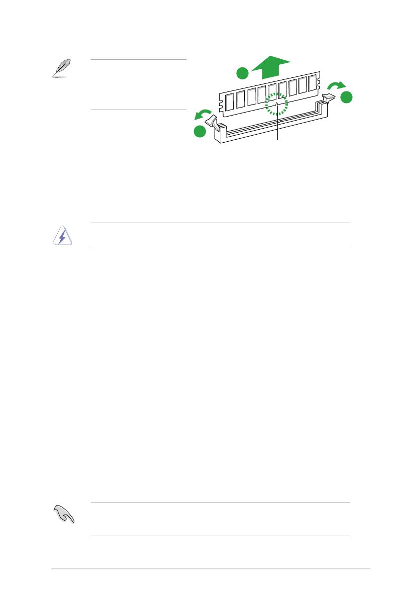
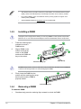
1.4.4 Removing a DIMM
To remove a DIMM:
1. Simultaneously press the retaining clips outward to unlock the DIMM.
Unlocked retaining clip
1
DIMM notch
2
1
DIMM slot key
Locked Retaining Clip
3
ASUS B85-A 1-9
2. Remove the DIMM from the socket.
Support the DIMM lightly with
your ngers when pressing the
retaining clips. The DIMM might
get damaged when it ips out
with extra force.
1.5 Expansion slots
In the future, you may need to install expansion cards. The following sub-sections describe
the slots and the expansion cards that they support.
Unplug the power cord before adding or removing expansion cards. Failure to do so may
cause you physical injury and damage motherboard components.
1.5.1 Installing an expansion card
To install an expansion card:
1. Before installing the expansion card, read the documentation that came with it and
make the necessary hardware settings for the card.
2. Remove the system unit cover (if your motherboard is already installed in a chassis).
3. Remove the bracket opposite the slot that you intend to use. Keep the screw for later
use.
4. Align the card connector with the slot and press rmly until the card is completely
seated on the slot.
5. Secure the card to the chassis with the screw you removed earlier.
6. Replace the system cover.
1.5.2 Conguring an expansion card
After installing the expansion card, congure it by adjusting the software settings.
1. Turn on the system and change the necessary BIOS settings, if any. See Chapter 2 for
information on BIOS setup.
2. Assign an IRQ to the card.
3. Install the software drivers for the expansion card.
When using PCI cards on shared slots, ensure that the drivers support “Share IRQ” or that
the cards do not need IRQ assignments. Otherwise, conicts will arise between the two PCI
groups, making the system unstable and the card inoperable.
DIMM notch
1
1
2
1-10 Chapter 1: Product introduction
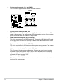
1.5.3 PCI slots
The PCI slot supports cards such as a LAN card, SCSI card, USB card, and other cards that
comply with PCI specications.
1.5.3 PCI Express 2.0 x1 slots
This motherboard supports PCI Express x1 network cards, SCSI cards, and other cards that
comply with the PCI Express specications.
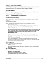
1.5.4 PCI Express x16 slots
This motherboard has two PCI Express x16 slots that support PCI Express x16 graphic cards
complying with the PCI Express specications.
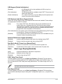
1.6 Jumpers
1. Clear RTC RAM (3-pin CLRTC)
This jumper allows you to clear the Real Time Clock (RTC) RAM in CMOS. You can
clear the CMOS memory of date, time, and system setup parameters by erasing
the CMOS RTC RAM data. The onboard button cell battery powers the RAM data in
CMOS, which include system setup information such as system passwords.
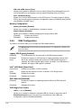
IRQ assignments for this motherboard
A B C D E F G H
IGD shared – – – – – – –
Audio Controller – – – – – – shared –
EHCI 1 Controller – – – – – – – shared
EHCI 2 Controller – – – – shared – – –
XHCI Controller – – – – – shared – –
SATA Controller – – – shared – – – –
PCIE x16_1 shared – – – – – – –
PCIE x16_2 shared – – – – – – –
PCIE x1_1 shared – – – – – – –
PCIE x1_2 – shared – – – – – –
RTL8111G – – shared – – – – –
PCI Slot 1 – – – shared – – – –
PCI Slot 2 shared – – – – – – –
PCI Slot 3 – shared – – – – – –

ASUS B85-A 1-11
B85-A
B85-A Clear RTC RAM
1 2 2 3
Normal
(Default)
Clear RTC
CLRTC
To erase the RTC RAM:
1. Turn OFF the computer and unplug the power cord.
2. Move the jumper cap from pins 1-2 (default) to pins 2-3. Keep the cap on pins 2-3
for about 5-10 seconds, then move the cap back to pins 1-2.
3. Plug the power cord and turn ON the computer.
• If the steps above do not help, remove the onboard battery and move the jumper
again to clear the CMOS RTC RAM data. After clearing the CMOS, reinstall the
battery.
• You do not need to clear the RTC when the system hangs due to overclocking. For
system failure due to overclocking, use the CPU Parameter Recall (C.P.R.) feature.
Shut down and reboot the system, then the BIOS automatically resets parameter
settings to default values.
4. Hold down the <Del> key during the boot process and enter BIOS setup to re-
enter data.
Except when clearing the RTC RAM, never remove the cap on CLRTC jumper default
position. Removing the cap will cause system boot failure!
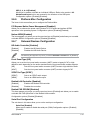
1.7 Connectors
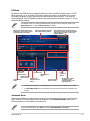
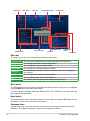
1.7.1 Rear panel connectors
4 53
68
9 7
1
11
2
10
1-12 Chapter 1: Product introduction
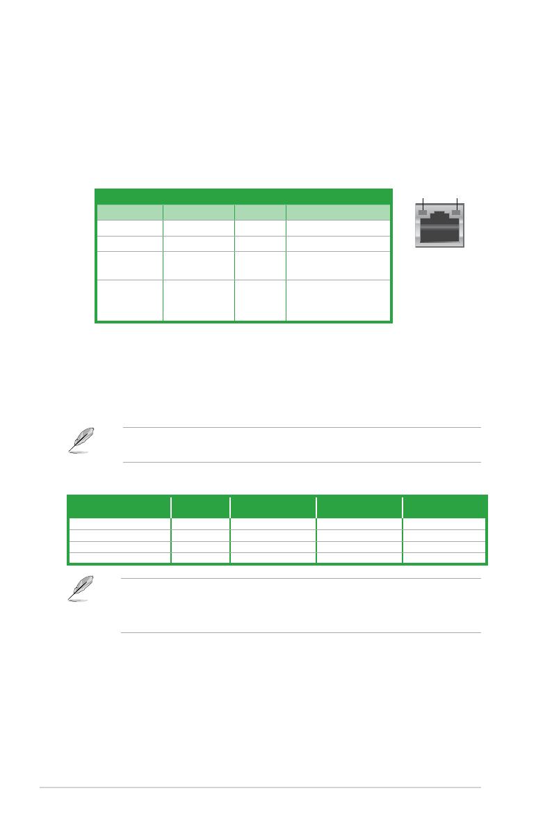
LAN port
Speed
LED
Activity Link
LED
1. PS/2 mouse port (green). This port is for a PS/2 mouse.
2. Video Graphics Adapter (VGA) port. This 15-pin port is for a VGA monitor or other
VGA-compatible devices.
3. LAN (RJ-45) port. This port allows Gigabit connection to a Local Area Network (LAN)
through a network hub.
LAN port LED indications
4. Line In port (light blue). This port connects to the tape, CD, DVD player, or other
audio sources.
5. Line Out port (lime). This port connects to a headphone or a speaker. In the 4, 6 and
8-channel congurations, the function of this port becomes Front Speaker Out.
Refer to the audio conguration table for the function of the audio ports in 2, 4, 6, or 8-
channel conguration.
Audio 2, 4, 6, or 8-channel conguration
Port Headset
2-channel 4-channel 6-channel 8-channel
Light Blue (Rear panel) Line In Rear Speaker Out Rear Speaker Out Rear Speaker Out
Lime (Rear panel) Line Out Front Speaker Out Front Speaker Out Front Speaker Out
Pink (Rear panel) Mic In Mic In Bass/Center Bass/Center
Lime (Front panel) - - - Side Speaker Out
6. Microphone port (pink). This port connects to a microphone.
To congure an 8-channel audio output:
Use a chassis with HD audio module in the front panel to support an 8-channel audio
output.
7. USB 2.0 ports 3 and 4. These two 4-pin Universal Serial Bus (USB) ports are for USB
2.0/1.1 devices.
8. USB 3.0 ports 5 and 6. These two 9-pin Universal Serial Bus (USB) ports are for USB
3.0 devices.
Activity/Link LED Speed LED
Status Description Status Description
Off No link OFF 10Mbps connection
Orange Linked ORANGE 100Mbps connection
Orange
(Blinking)
Data activity GREEN 1Gbps connection
Orange
(Blinking
then steady)
Ready to
wake up from
S5 mode
Page is loading ...
Page is loading ...
Page is loading ...
Page is loading ...
Page is loading ...
Page is loading ...
Page is loading ...
Page is loading ...
Page is loading ...
Page is loading ...
Page is loading ...
Page is loading ...
Page is loading ...
Page is loading ...
Page is loading ...
Page is loading ...
Page is loading ...
Page is loading ...
Page is loading ...
Page is loading ...
Page is loading ...
Page is loading ...
Page is loading ...
Page is loading ...
Page is loading ...
Page is loading ...
Page is loading ...
Page is loading ...
Page is loading ...
Page is loading ...
Page is loading ...
Page is loading ...
Page is loading ...
Page is loading ...
Page is loading ...
Page is loading ...
Page is loading ...
Page is loading ...
Page is loading ...
Page is loading ...
Page is loading ...
Page is loading ...
Page is loading ...
Page is loading ...
Page is loading ...
Page is loading ...
Page is loading ...
Page is loading ...
Page is loading ...
Page is loading ...
Page is loading ...
Page is loading ...
Page is loading ...
Page is loading ...
Page is loading ...
-
 1
1
-
 2
2
-
 3
3
-
 4
4
-
 5
5
-
 6
6
-
 7
7
-
 8
8
-
 9
9
-
 10
10
-
 11
11
-
 12
12
-
 13
13
-
 14
14
-
 15
15
-
 16
16
-
 17
17
-
 18
18
-
 19
19
-
 20
20
-
 21
21
-
 22
22
-
 23
23
-
 24
24
-
 25
25
-
 26
26
-
 27
27
-
 28
28
-
 29
29
-
 30
30
-
 31
31
-
 32
32
-
 33
33
-
 34
34
-
 35
35
-
 36
36
-
 37
37
-
 38
38
-
 39
39
-
 40
40
-
 41
41
-
 42
42
-
 43
43
-
 44
44
-
 45
45
-
 46
46
-
 47
47
-
 48
48
-
 49
49
-
 50
50
-
 51
51
-
 52
52
-
 53
53
-
 54
54
-
 55
55
-
 56
56
-
 57
57
-
 58
58
-
 59
59
-
 60
60
-
 61
61
-
 62
62
-
 63
63
-
 64
64
-
 65
65
-
 66
66
-
 67
67
-
 68
68
-
 69
69
-
 70
70
-
 71
71
-
 72
72
-
 73
73
-
 74
74
-
 75
75


Asus B85-A User manual
- Category
- Server/workstation motherboards
- Type
- User manual
Ask a question and I''ll find the answer in the document
Finding information in a document is now easier with AI