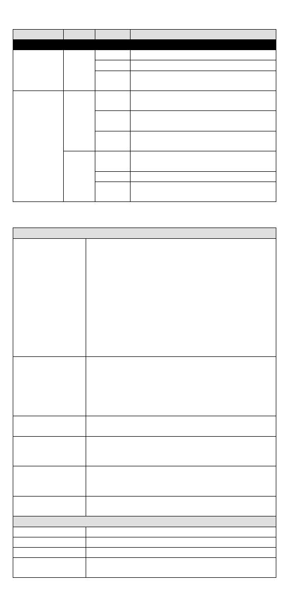
Moxa IKS-G6524A Series Quick setup guide

Category
Network switches
Type
Quick setup guide

This manual is also suitable for

Moxa IKS-G6524A Series industrial rackmount switches are designed for harsh environments and offer a range of features for reliable network connectivity. With 24 Gigabit Ethernet ports, including 16 RJ45 copper ports and 8 SFP slots for fiber connections, these switches provide flexible connectivity options for demanding industrial applications. The IKS-G6524A Series supports advanced features such as Turbo Ring and Turbo Chain for fast network recovery in the event of a link failure, ensuring uninterrupted data transmission.

Moxa IKS-G6524A Series industrial rackmount switches are designed for harsh environments and offer a range of features for reliable network connectivity. With 24 Gigabit Ethernet ports, including 16 RJ45 copper ports and 8 SFP slots for fiber connections, these switches provide flexible connectivity options for demanding industrial applications. The IKS-G6524A Series supports advanced features such as Turbo Ring and Turbo Chain for fast network recovery in the event of a link failure, ensuring uninterrupted data transmission.

P/N: 1802065240027
*1802065240027*
IKS-G6524A/G6824A Series
Quick Installation Guide
Version 3.5, April 2023
Technical Support Contact Information
www.moxa.com/support
2023 Moxa Inc. All rights reserved.
- 2 -
Package Checklist
The Moxa IKS-G6524A/G6824A Series industrial rackmount switches
are shipped with the following items. If any of these items are missing
or damaged, please contact your customer service representative for
assistance.
IKS-G6524A/G6824A switch
USB cable (Type A male to Type B male)
Power cord
4 protective caps for unused ports
2 rackmount ears
Quick installation guide (printed)
Warranty card
Panel Layouts
1. Model Name
2. System status LEDs
3. 10/100/1000BaseT(X) port status LEDs
4. 100/1000BaseSFP port status LEDs
5. 10/100/1000BaseT(X) port
6. 100/1000BaseSFP slot
7. 10/100/1000BaseT(X) or 100/1000BaseSFP slot combo ports
8. Reset button
9. USB serial console port
10. USB storage port (ABC-02-USB)
11. Terminal block for Relay Output, Digital Input
12. AC power sockets for power inputs
13. Grounding screw
- 3 -
Dimensions (unit = mm)
Grounding the Industrial Rackmount Switch
Grounding and routing the wire to the protective conductor terminal
(protective earth) helps limit the effects of noise due to
electromagnetic interference (EMI).
We suggest using the cable typeAWG (American Wire Gauge) 22
as minimum size.
Insert the exposed grounding wire all the way into the hole of the
grounding plug.
Run the ground connection from the ground screw to the grounding
surface prior to connecting devices.
Connecting the Power Inputs
The IKS-G6524A/G6824A series of switches supports dual redundant
power supplies: Power Supply 1 (PWR1) and Power Supply 2 (PWR2).
The connections for PWR1 and PWR2 are located on the rear side
(shown below). Be sure to use a standard power cord with an IEC C13
connector, which is compatible with the AC power inlet.
- 4 -
Wiring the Relay Contact
Each IKS-G6524A/G6824A switch has one relay output.
FAULT:
The relay contact of the 4-pin terminal block connector is used to detect
user-configured events. The two wires attached to the fault contacts
form an open circuit when a user-configured event is triggered. If a
user-configured event does not occur, the fault circuit remains closed.
USB Console Connection
The IKS-G6524A/G6824A series has one USB console port (type B
connector), located on the top panel. Use the USB cable (provided in
the product package) to connect the IKS-G6524A/G6824A’s console
port to your PCs USB port and install the USB driver (available in the
software CD) on the PC. You may then use a console terminal program,
such as Moxa PComm Terminal Emulator, to access the IKS-
G6524A/G6824A’s console configuration utility.
USB Console Port (Type B Connector) Pinouts
Pin
Description
1
D– (Data -)
2
VCC (+5V)
3
D+ (Data+)
4
GND (Ground)
USB Storage Connection
The IKS-G6524A/G6824A series has one USB storage port (type A
connector) on the front panel. Use the Moxa ABC-02-USB automatic
backup configurator to connect the IKS-G6524A/G6824A’s USB storage
port for configuration backup, firmware upgrade, or system log file
backup.
USB Storage Port (Type A Connector) Pinouts
Description
VCC (+5V)
D– (Data -)
D+ (Data+)
GND (Ground)
NOTE
DO NOT pull out the ABC-02-USB automatic backup
configurator from the USB port while writing or reading data.
The Reset Button
Press the Reset button for five continuous seconds to load the factory
default settings. Use a pointed object, such as a straightened paper clip
or toothpick, to press the Reset button. When you do so, the STATE
LED will start to blink about once per second. Continue to press the
STATE LED until it begins blinking more rapidly, indicating that the
button has been pressed continuously for five seconds. You can now
release the Reset button to load factory default settings.
- 5 -
NOTE
DO NOT power off the switch when loading default settings.
LED Indicators
The front panel of the IKS-G6524A/G6824A Series switch contains
several LED indicators. The function of each LED is described in the
following table.
LED
Color
State
Description
System LEDs
STATE
GREEN
On
The system has passed the self-
diagnosis test on boot-up and is ready
to run.
Blinking
1. System is undergoing the self-
diagnosis test.
2. Blinks continuously when pressing
the reset button 5 seconds to reset
to factory default.
3. Blinks slowly when an ABC-02
automatic backup device is
detected.
RED On
The system failed self-diagnosis on
boot-up.
PWR1 AMBER
On Power is being supplied to the main
module’s power input PWR1.
Off
Power is not being supplied to the main
module’s power input PWR1.
PWR2 AMBER
On
Power is being supplied to the main
module’s power input PWR2.
Off Power is not being supplied to the main
module’s power input PWR2.
FAULT RED On
The system has failed, or is under quick
inspection.
Off
The system is operating normally.
MSTR/
HEAD GREEN
On
The switch is set as the Master of the
Turbo Ring, or as the Head of the Turbo
Chain.
Blinking
The switch has become the Ring Master
of the Turbo Ring, or the Head of the
Turbo Chain, after the Turbo Ring or
the Turbo Chain is down.
Off
The switch is not the Master of this
Turbo Ring or is set as a Member of the
Turbo Chain.
CPLR/
TAIL GREEN
On
The switch’s coupling function is
enabled to form a back-up path, or
when it’s set as the Tail of the Turbo
Chain.
Blinking
Turbo Chain is down.
Off The switch disables the coupling
function.
When the system is importing/exporting data from or to an ABC-02
automatic backup device, the FAULT, MSTR/HEAD, and CPLR/TAIL LEDs
will blink in sequence.
- 6 -
LED
Color
State
Description
Port Status LEDs
10/100/
1000M
(TP ports)
GREEN
On
The corresponding port’s link is active.
Blinking
Data is being transmitted.
Off The corresponding port’s link is
inactive.
100/1000M
(Fiber Optic
ports)
GREEN
On
The corresponding port's link is active
at 1000 Mbps.
Blinking
Data is being transmitted at 1000
Mbps.
Off
The corresponding port’s link is
inactive.
AMBER
On The corresponding port's link is active
at 100 Mbps.
Blinking
Data is being transmitted at 100 Mbps.
Off
The corresponding port’s link is
inactive.
Specifications
Technology
Standards
IEEE 802.3 for 10BaseT
IEEE 802.3u for 100BaseT(X) and 100BaseFX
IEEE 802.3ab for 1000BaseT(X)
IEEE 802.3z for 1000BaseSX/LX/LHX/ZX
IEEE 802.3x for Flow Control
IEEE 802.1D-2004 for Spanning Tree Protocol
IEEE 802.1w for Rapid Spanning Tree Protocol
IEEE 802.1s for Multiple Spanning Tree Protocol
IEEE 802.1Q for VLAN Tagging
IEEE 802.1p for Class of Service
IEEE 802.1X for Authentication
IEEE 802.3ad for Port Trunk with LACP
Protocols IGMPv1/v2, GMRP, GVRP, SNMPv1/v2c/v3, DHCP
Server/Client, BootP, TFTP, SNTP, SMTP, RARP,
RMON, HTTP, HTTPS, Telnet, Syslog, DHCP Option
66/67/82, SSH, LLDP, IEEE 1588 PTP V2,
EtherNet/IP, Modbus/TCP, PROFINET, SNMP
Inform, NTP Server/Client, IPv6 (IKS-G6524A)
Layer 3 Switching
(IKS-G6824A)
Static routing, RIP V1/V2, OSPF, DVMRP, PIM-DM,
PIM-SM, PIM-SSM
Layer 3 Switching
Redundancy (IKS-
G6824A)
VRRP
MIB MIB-II, Ethernet-like MIB, P-BRIDGE MIB, Q-
BRIDGE MIB, Bridge MIB, RSTP MIB, RMON MIB
Groups 1, 2, 3, 9
Flow Control
IEEE 802.3x flow control, back pressure flow
control
Interface
Gigabit Ethernet
10/100/1000BaseT(X) or 100/1000BaseSFP slot
Console Port
USB-serial console (Type B connector)
Storage Port
USB storage (Type A connector for ABC-02-USB)
LED Indicators
STATE, PWR1, PWR2, FAULT, MSTR/HEAD,
CPLR/TAIL
- 7 -
Alarm Contact
1 relay output with current carrying capacity of
2 A @ 30 VDC
Digital Inputs
1 input with the same ground, but electrically
isolated from the electronics.
• +13 to +30V for state “1”
-30 to +1V for state “0”
• Max. input current: 8 mA
Power Requirements
Input Voltage
100 to 240 VAC
Operating Voltage
85 to 264 VAC
Input Current
Max. 0.66/0.39 A @ 110/220 VAC
Power
Consumption
Max. 37.83 W @ 110 VAC
Max. 40.15 W @ 220 VAC
Overload Current
Protection
Present
Reverse Polarity
Protection
Present
Physical Characteristics
Housing
IP 30 protection
Dimensions
440 x 44 x 386.9 mm (17.32 x 1.73 x 15.23 in)
Installation
19rack mounting
Environmental Limits
Operating Temp. Standard Models: -10 to 60°C (14 to 140°F)
Wide Temp. Models: -40 to 75°C (-40 to 167°F)
Storage Temp.
-40 to 85°C (-40 to 185°F)
Ambient Relative
Humidity.
5 to 95% (non-condensing)
Standards and Certifications
Safety
UL 61010-2-201, EN 61010-2-201, UL 62368-1,
IEC 62368-1
EMI
FCC Part 15 Subpart B Class A, EN 55032 Class A
EMS
EN 61000-4-2 (ESD) Level 3
EN 61000-4-3 (RS) Level 3
EN 61000-4-4 (EFT) Level 3
EN 61000-4-5 (Surge) Level 3
EN 61000-4-6 (CS) Level 3
EN 61000-4-8
EN 61000-4-11
Rail Traffic
EN 50121-4
Shock
IEC 60068-2-27
Freefall
IEC 60068-2-32
Vibration
IEC 60068-2-6
Warranty
Warranty Period
5 years
Details
See www.moxa.com/warranty
- 8 -
Rack Mounting Instructions
1. Elevated Operating Ambient: If installed in a closed or multi-unit
rack assembly, the operating ambient temperature of the rack
environment may be greater than room ambient. Therefore,
consideration should be given to installing the equipment in an
environment compatible with the maximum ambient temperature
(Tma) specified by the manufacturer.
2. Reduced Air Flow: Installation of the equipment in a rack should
be such that the amount of air flow required for safe operation of
the equipment is not compromised.
3. Mechanical Loading: Mounting of the equipment in the rack
should be such that a hazardous condition is not achieved due to
uneven mechanical loading.
4. Circuit Overloading: Consideration should be given to the
connection of the equipment to the supply circuit and the effect
that overloading of the circuits might have on overcurrent
protection and supply wiring. Appropriate consideration of
equipment nameplate ratings should be used when addressing this
concern.
5. Reliable Earthing: Reliable earthing of rack-mounted equipment
should be maintained. Particular attention should be given to supply
connections other than direct connections to the branch circuit (e.g.
use of power strips)."
Restricted Access Locations
This equipment is intended to be used in Restricted
Access Locations, such as a computer room, with
access limited to SERVICE PERSONAL or USERS who
have been instructed on how to handle the metal
chassis of
equipment that is so hot that special protection may be needed
before touching it. The location should only be accessible with a
key
or through a security identity system.
External metal parts of this equipment are extremely hot!! Before
touching the equipment, you must take special precautions to
protect your hands and body from serious injury.
- 9 -
ATTENTION
1. This device is only for indoor use and Pollution degree 2.
2. Conductors rated to withstand at least 105°C must be
used for the Power Supply Terminal.
3. When wiring the relay contact and digital input, we
suggest using the cable type - AWG (American Wire
Gauge) 16-24 and the corresponding pin type cable
terminals. The connector must be able to withstand
torque at a maximum of 4.5 pound-inches. Use copper
conductors only.
4. The equipment has a separate protective earthing
terminal on the chassis that must be permanently
connected to earth ground to adequately ground the
chassis and protect the operator from electrical hazards.
To avoid risks of electric shock, do not replace or remove
the protective conductor.
5. The IP rating is not part of the safety certification.
6. This device must be installed within a suitable enclosure.
7. The cable that is connected to the field wiring terminals
must be able to withstand at least 75°C.
8. Altitudes of up to 2000 m.
9. Transient overvoltage up to the levels of overvoltage
category II.
10. Mains supply voltage fluctuations up to ±10% of the
nominal voltage.
11. Temporary overvoltage occurring on the mains supply.
12. Clean the device with a soft dry or wet cloth.
13. For any repair or maintenance needs, please contact us.
WARNING
Please employ an optional optical transceiver (SFP) that
complies with IEC 60825-1, 21 CFR 1040 Section 1040.10
and 1040.11. It is classified as a Class 1 laser product.
The safety of the installation to any system incorporating
the equipment is the responsibility of the assembler of the
system.
The device is an open type piece of equipment and is
intended to be installed in a suitable enclosure.
If the equipment is used in a manner not specified by the
manufacturer, the protection provided by the equipment
may be impaired. The manufacturer is not responsible for
any accident caused by the scenario mentioned above.
Shock hazard
CAUTION
TO
DISCONNECT POWER, REMOVE ALL POWER
CORDS FROM UNIT.
- 10 -
ATTENTION
DÉBRANCHER LES TOUT CORDONS
D'ALIMENTATION POUR DÉCONNECTER L'UNITÉ DU
SECTEUR
  • Page 1 1
  • Page 2 2
  • Page 3 3
  • Page 4 4
  • Page 5 5
  • Page 6 6
  • Page 7 7
  • Page 8 8
  • Page 9 9
  • Page 10 10

Moxa IKS-G6524A Series Quick setup guide

Category
Network switches
Type
Quick setup guide
This manual is also suitable for

Moxa IKS-G6524A Series industrial rackmount switches are designed for harsh environments and offer a range of features for reliable network connectivity. With 24 Gigabit Ethernet ports, including 16 RJ45 copper ports and 8 SFP slots for fiber connections, these switches provide flexible connectivity options for demanding industrial applications. The IKS-G6524A Series supports advanced features such as Turbo Ring and Turbo Chain for fast network recovery in the event of a link failure, ensuring uninterrupted data transmission.

Ask a question and I''ll find the answer in the document

Finding information in a document is now easier with AI