
Form No. 3441-302 Rev B
TX 525 Compact T ool Carrier
Model No. 22323 —Serial No. 407600000 and Up
Model No. 22323G —Serial No. 405700000 and Up
Model No. 22323HD —Serial No. 400000000 and Up
Model No. 22324 —Serial No. 407600000 and Up
Register at www .T oro.com.
Original Instructions (EN)
*3441-302*

This product complies with all relevant European
directives; for details, please see the separate product
specic Declaration of Conformity (DOC) sheet.
It is a violation of California Public Resource Code
Section 4442 or 4443 to use or operate the engine on
any forest-covered, brush-covered, or grass-covered
land unless the engine is equipped with a spark
arrester , as dened in Section 4442, maintained in
ef fective working order or the engine is constructed,
equipped, and maintained for the prevention of re.
The enclosed engine owner's manual is supplied
for information regarding the US Environmental
Protection Agency (EP A) and the California Emission
Control Regulation of emission systems, maintenance,
and warranty . Replacements may be ordered through
the engine manufacturer .
W ARNING
CALIFORNIA
Proposition 65 W arning
Diesel engine exhaust and some of its
constituents are known to the State of
California to cause cancer , birth defects,
and other reproductive harm.
Battery posts, terminals, and related
accessories contain lead and lead
compounds, chemicals known to
the State of California to cause
cancer and reproductive harm. W ash
hands after handling.
Use of this product may cause exposure
to chemicals known to the State of
California to cause cancer , birth defects,
or other reproductive harm.
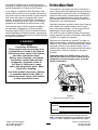
Introduction
This machine is a compact tool carrier intended for
use in various earth and materials moving activities for
landscaping and construction work. It is designed to
operate a wide variety of attachments each of which
perform a specialized function. Using this product
for purposes other than its intended use could prove
dangerous to you and bystanders.
Read this information carefully to learn how to operate
and maintain your product properly and to avoid
injury and product damage. Y ou are responsible for
operating the product properly and safely .
V isit www .T oro.com for product safety and operation
training materials, accessory information, help nding
a dealer , or to register your product.
Whenever you need service, genuine T oro parts, or
additional information, contact an Authorized Service
Dealer or T oro Customer Service and have the model
and serial numbers of your product ready . Figure 1
identies the location of the model and serial numbers
on the product. W rite the numbers in the space
provided.
Important: W ith your mobile device, you can
scan the QR code on the serial number decal (if
equipped) to access warranty , parts, and other
product information.
g243442
Figure 1
1. Model and serial number location
Model No.
Serial No.
This manual identies potential hazards and has
safety messages identied by the safety-alert symbol
(Figure 2 ), which signals a hazard that may cause
© 2023—The T oro® Company
81 1 1 L yndale A venue South
Bloomington, MN 55420
2
Contact us at www .T oro.com.
Printed in the USA
All Rights Reserved

serious injury or death if you do not follow the
recommended precautions.
g000502
Figure 2
1. Safety-alert symbol
This manual uses 2 words to highlight information.
Important calls attention to special mechanical
information and Note emphasizes general information
worthy of special attention.
Contents
Safety . . . . . . . . . . . . . . . . . . . . . . . . . . . . . . . . . . . . . . . . . . . . . . . . . . . . . . . . . . . . . . . . . . . . . . . 4
General Safety . . . . . . . . . . . . . . . . . . . . . . . . . . . . . . . . . . . . . . . . . . . . . . . . . . . 4
Safety and Instructional Decals . . . . . . . . . . . . . . . . . . . . . . . . . . 5
Product Overview . . . . . . . . . . . . . . . . . . . . . . . . . . . . . . . . . . . . . . . . . . . . . . . . . . . . . 9
Controls . . . . . . . . . . . . . . . . . . . . . . . . . . . . . . . . . . . . . . . . . . . . . . . . . . . . . . . . . . . . . 9
Specications . . . . . . . . . . . . . . . . . . . . . . . . . . . . . . . . . . . . . . . . . . . . . . . . . . 13
Attachments/Accessories . . . . . . . . . . . . . . . . . . . . . . . . . . . . . . . . . 13
Before Operation . . . . . . . . . . . . . . . . . . . . . . . . . . . . . . . . . . . . . . . . . . . . . . . . . 13
Before Operation Safety . . . . . . . . . . . . . . . . . . . . . . . . . . . . . . . . . . . 13
Adding Fuel . . . . . . . . . . . . . . . . . . . . . . . . . . . . . . . . . . . . . . . . . . . . . . . . . . . . . . 14
Performing Daily Maintenance . . . . . . . . . . . . . . . . . . . . . . . . . . 15
During Operation . . . . . . . . . . . . . . . . . . . . . . . . . . . . . . . . . . . . . . . . . . . . . . . . . 15
During Operation Safety . . . . . . . . . . . . . . . . . . . . . . . . . . . . . . . . . . . 15
Starting the Engine . . . . . . . . . . . . . . . . . . . . . . . . . . . . . . . . . . . . . . . . . . . 16
Driving the Machine . . . . . . . . . . . . . . . . . . . . . . . . . . . . . . . . . . . . . . . . . . 17
Shutting Of f the Engine . . . . . . . . . . . . . . . . . . . . . . . . . . . . . . . . . . . . . 17
Using Attachments . . . . . . . . . . . . . . . . . . . . . . . . . . . . . . . . . . . . . . . . . . . 17
After Operation . . . . . . . . . . . . . . . . . . . . . . . . . . . . . . . . . . . . . . . . . . . . . . . . . . . . 19
After Operation Safety . . . . . . . . . . . . . . . . . . . . . . . . . . . . . . . . . . . . . . 19
Moving a Non-Functioning Machine . . . . . . . . . . . . . . . . . . 19
Hauling the Machine . . . . . . . . . . . . . . . . . . . . . . . . . . . . . . . . . . . . . . . . . 20
Lifting the Machine . . . . . . . . . . . . . . . . . . . . . . . . . . . . . . . . . . . . . . . . . . . 21
Maintenance . . . . . . . . . . . . . . . . . . . . . . . . . . . . . . . . . . . . . . . . . . . . . . . . . . . . . . . . . . . 22
Maintenance Safety . . . . . . . . . . . . . . . . . . . . . . . . . . . . . . . . . . . . . . . . . . 22
Recommended Maintenance Schedule(s) . . . . . . . . . . . 22
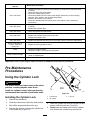
Pre-Maintenance Procedures . . . . . . . . . . . . . . . . . . . . . . . . . . . . . . 23
Using the Cylinder Lock . . . . . . . . . . . . . . . . . . . . . . . . . . . . . . . . . . . . 23
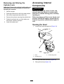
Accessing Internal Components . . . . . . . . . . . . . . . . . . . . . . . 24
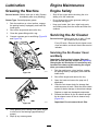
Lubrication . . . . . . . . . . . . . . . . . . . . . . . . . . . . . . . . . . . . . . . . . . . . . . . . . . . . . . . . . . 26
Greasing the Machine . . . . . . . . . . . . . . . . . . . . . . . . . . . . . . . . . . . . . . . 26
Engine Maintenance . . . . . . . . . . . . . . . . . . . . . . . . . . . . . . . . . . . . . . . . . . . 26
Engine Safety . . . . . . . . . . . . . . . . . . . . . . . . . . . . . . . . . . . . . . . . . . . . . . . . . . . 26
Servicing the Air Cleaner . . . . . . . . . . . . . . . . . . . . . . . . . . . . . . . . . . 26
Servicing the Engine Oil . . . . . . . . . . . . . . . . . . . . . . . . . . . . . . . . . . . . 27
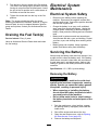
Fuel System Maintenance . . . . . . . . . . . . . . . . . . . . . . . . . . . . . . . . . . . 29
Checking the Fuel Lines and
Connections . . . . . . . . . . . . . . . . . . . . . . . . . . . . . . . . . . . . . . . . . . . . . . . . . . 29
Draining the Fuel Filter/W ater Separator . . . . . . . . . . . 29
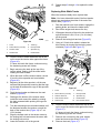
Replacing the Fuel Filter Canister and
In-Line Filter . . . . . . . . . . . . . . . . . . . . . . . . . . . . . . . . . . . . . . . . . . . . . . . . . . 30
Bleeding the Fuel System . . . . . . . . . . . . . . . . . . . . . . . . . . . . . . . . . 30
Draining the Fuel T ank(s) . . . . . . . . . . . . . . . . . . . . . . . . . . . . . . . . . . 31
Electrical System Maintenance . . . . . . . . . . . . . . . . . . . . . . . . . . . 31
Electrical System Safety . . . . . . . . . . . . . . . . . . . . . . . . . . . . . . . . . . . 31
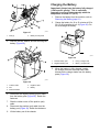
Servicing the Battery . . . . . . . . . . . . . . . . . . . . . . . . . . . . . . . . . . . . . . . . . 31
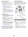
Servicing the Fuses . . . . . . . . . . . . . . . . . . . . . . . . . . . . . . . . . . . . . . . . . . 33
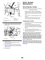
Drive System Maintenance . . . . . . . . . . . . . . . . . . . . . . . . . . . . . . . . . . 34
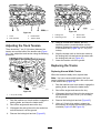
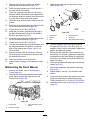
Servicing the T racks . . . . . . . . . . . . . . . . . . . . . . . . . . . . . . . . . . . . . . . . . 34
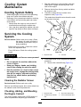
Cooling System Maintenance . . . . . . . . . . . . . . . . . . . . . . . . . . . . . . 38
Cooling System Safety . . . . . . . . . . . . . . . . . . . . . . . . . . . . . . . . . . . . . 38
Servicing the Cooling System . . . . . . . . . . . . . . . . . . . . . . . . . . . 38
Brake Maintenance . . . . . . . . . . . . . . . . . . . . . . . . . . . . . . . . . . . . . . . . . . . . . 39
T esting the Parking Brake . . . . . . . . . . . . . . . . . . . . . . . . . . . . . . . . . 39
Belt Maintenance . . . . . . . . . . . . . . . . . . . . . . . . . . . . . . . . . . . . . . . . . . . . . . . . 40
Checking the Condition of the Hydraulic
Pump Belt . . . . . . . . . . . . . . . . . . . . . . . . . . . . . . . . . . . . . . . . . . . . . . . . . . . . . 40
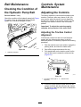
Controls System Maintenance . . . . . . . . . . . . . . . . . . . . . . . . . . . . . 40
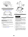
Adjusting the Controls . . . . . . . . . . . . . . . . . . . . . . . . . . . . . . . . . . . . . . . 40
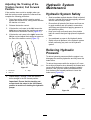
Hydraulic System Maintenance . . . . . . . . . . . . . . . . . . . . . . . . . . . 42
Hydraulic System Safety . . . . . . . . . . . . . . . . . . . . . . . . . . . . . . . . . . . 42
Relieving Hydraulic Pressure . . . . . . . . . . . . . . . . . . . . . . . . . . . . 42
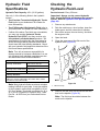
Hydraulic Fluid Specications . . . . . . . . . . . . . . . . . . . . . . . . . . . 43
Checking the Hydraulic-Fluid Level . . . . . . . . . . . . . . . . . . . 43
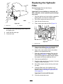
Replacing the Hydraulic Filter . . . . . . . . . . . . . . . . . . . . . . . . . . . 44
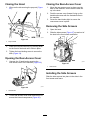
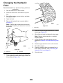
Changing the Hydraulic Fluid . . . . . . . . . . . . . . . . . . . . . . . . . . . . 45
Cleaning . . . . . . . . . . . . . . . . . . . . . . . . . . . . . . . . . . . . . . . . . . . . . . . . . . . . . . . . . . . . . . 46
Removing Debris . . . . . . . . . . . . . . . . . . . . . . . . . . . . . . . . . . . . . . . . . . . . . . 46
Cleaning the Chassis . . . . . . . . . . . . . . . . . . . . . . . . . . . . . . . . . . . . . . . . 46
Storage . . . . . . . . . . . . . . . . . . . . . . . . . . . . . . . . . . . . . . . . . . . . . . . . . . . . . . . . . . . . . . . . . . . 46
Storage Safety . . . . . . . . . . . . . . . . . . . . . . . . . . . . . . . . . . . . . . . . . . . . . . . . . . 46
Storage . . . . . . . . . . . . . . . . . . . . . . . . . . . . . . . . . . . . . . . . . . . . . . . . . . . . . . . . . . . . . 46
T roubleshooting . . . . . . . . . . . . . . . . . . . . . . . . . . . . . . . . . . . . . . . . . . . . . . . . . . . . . . 47
3

Safety
General Safety
DANGER
There may be buried utility lines in the work
area. Digging into them may cause a shock
or an explosion.
Have the property or work area marked for
buried lines and do not dig in marked areas.
Contact your local marking service or utility
company to have the property marked (for
example, in the US, call 81 1 or in Australia,
call 1 100 for the nationwide marking service).
Always follow all safety instructions to avoid serious
injury or death.
•Do not exceed the rated operating capacity , as the
machine may become unstable, which may result
in loss of control.
•Do not carry a load with the arms raised; always
carry loads close to the ground.
•Slopes are a major factor related to loss-of-control
and tip-over accidents, which can result in severe
injury or death. Operating the machine on any
slope or uneven terrain requires extra caution.
•Operate the machine up and down slopes with
the heavy end of the machine uphill and the
load close to the ground. W eight distribution
changes with attachments. An empty bucket
makes the rear of the machine the heavy end, and
a full bucket makes the front of the machine the
heavy end. Most other attachments make the front
of the machine the heavy end.
•Have the property or work area marked for buried
lines and other objects, and do not dig in marked
areas.
•Read and understand the content of this Operator ’ s
Manual before starting the engine.
•Use your full attention while operating the
machine. Do not engage in any activity that
causes distractions; otherwise, injury or property
damage may occur .
•Never allow children or untrained people to
operate the machine.
•Keep your hands and feet away from the moving
components and attachments.
•Do not operate the machine without the guards
and other safety protective devices in place and
working on the machine.
•Keep bystanders and children out of the operating
area.
•Stop the machine, shut of f the engine, and remove
the key before servicing, fueling, or unclogging
the machine.
Improperly using or maintaining this machine can
result in injury . T o reduce the potential for injury ,
comply with these safety instructions and always
pay attention to the safety-alert symbol , which
means Caution, W arning, or Danger—personal safety
instruction. Failure to comply with these instructions
may result in personal injury or death.
4

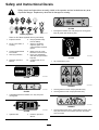
Safety and Instructional Decals
Safety decals and instructions are easily visible to the operator and are located near any area
of potential danger . Replace any decal that is damaged or missing.
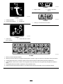
decalbatterysymbols
Battery Symbols
Some or all of these symbols are on your battery .
1. Explosion hazard 6. Keep bystanders away
from the battery .
2. No re, open ame, or
smoking
7. W ear eye protection;
explosive gases can
cause blindness and other
injuries.
3. Caustic liquid/chemical
burn hazard
8. Battery acid can cause
blindness or severe burns.
4. W ear eye protection. 9. Flush eyes immediately
with water and get medical
help fast.
5. Read the Operator's
Manual .
10. Contains lead; do not
discard
decal93-6680
93-6680
decal93-6681
93-6681
1. Cutting/dismemberment hazard, fan—stay away from
moving parts.
decal93-6686
93-6686
1. Hydraulic uid 2. Read the Operator's
Manual .
decal93-7814
93-7814
1. Entanglement hazard, belt—stay away from moving parts;
keep all guards and shields in place.
decal93-9084
93-9084
1. Lift point/T ie-down point
decal100-4650
100-4650
1. Crushing hazard of hand—keep bystanders away .
2. Crushing hazard of foot—keep bystanders away .
decal100-8821
100-8821
1. Crushing hazard from above; cutting hazard of hand—stay
away from the front of the traction unit when the loader
arms are raised.
5

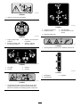
decal100-8822
100-8822
1. W arning—do not carry passengers.
decal106-6755
106-6755
1. Engine coolant under
pressure.
3. W arning—do not touch the
hot surface.
2. Explosion hazard—read
the Operator's Manual.
4. W arning—read the
Operator's Manual.
decal1 15-4020
1 15-4020
1. T urn right 3. Reverse
2. Forward
4. T urn left
decal1 15-4855
1 15-4855
1. Hot surface/burn hazard—wear protective gloves when
handling the hydraulic couplers and read the Operator's
Manual for information on handling hydraulic components.
decal1 15-4857
1 15-4857
1. Lower the loader arms.
4. Curl the bucket.
2. Dump the bucket. 5. Float the bucket on the
ground.
3. Raise the loader arms.
decal1 15-4858
1 15-4858
1. Crushing hazard of hands or feet—install the cylinder lock.
decal1 15-4859
1 15-4859
1. Disengaged 3. Engaged
2. Parking brake
6

decal1 15-4861
1 15-4861
1. Auxiliary hydraulics 3. Forward
2. Locked reverse (detent) 4. Neutral (of f)
decal1 15-4862
1 15-4862
1. Loader-valve
lock—unlocked
2. Loader-valve lock—locked
decal1 15-4865
1 15-4865
1. Engine coolant
2. Read the Operator's
Manual .
decal1 15-4882
1 15-4882
1. W arning—do not touch the hot surface.
decal1 15-4860
1 15-4860
1. W arning—read the Operator's Manual .
2. W arning—lower the loader arms, engage the parking brake, shut of f the engine, and remove the key before leaving the machine.
3. Crushing hazard from above—install the cylinder lock and read the Operator ’ s Manual before performing maintenance.
4. Cutting hazard of hands or feet—wait for all moving parts to stop; stay away from moving parts; keep all guards and shields in
place.
5. Crushing/dismemberment hazard of bystanders—keep bystanders away .
6. Explosion hazard; electrical shock hazard—do not operate if power lines may be present; call your local utility company .
7

decal138-0800
138-0800
1. Read the Operator ’ s Manual stored in your machine.
9. Battery
2. Engine—start
10. Glow plug
3. Engine—run 1 1. Fast
4. Engine—shut of f 12. Slow
5. Hour meter 13. W arning—do not operate this machine unless you are trained.
6. Fuel
14. Electrical shock hazard, overhead power lines—watch for
overhead power lines.
7. Engine coolant temperature 15. T ipping hazard—move the traction unit with the heavy end
uphill; carry loads low; do not drive the machine with the load
raised.
8. Engine oil pressure 16. T ipping hazard—drive slowly when turning; do not turn
sharply while traveling fast; look behind and down when
moving in reverse.
decal140-5729
140-5729
1. Read the Operator ’ s Manual .
8

Product Overview
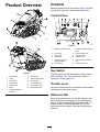
g313997
g313998
Figure 3
1. Road wheels 8. Mount plate
2. T rack
9. Reverse-safety plate
3. Lift cylinder 10. Control panel
4. Cylinder lock 1 1. T ie-down/lift loop
5. Loader arms 12. Rear-access cover
6. Hood
13. Side panel screen
7. Auxiliary hydraulic
couplers
Controls
Become familiar with all the controls ( Figure 4 ) before
you start the engine and operate the traction unit.
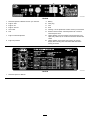
Control Panel
g013016
Figure 4
1. Auxiliary hydraulics lever
7. Loader-arm/attachment-tilt
lever
2. Key switch 8. Parking-brake lever
3. Hour meter 9. T raction control
4. Fuel gauge
10. Reference bar
5. Indicator lights and
glow-plug switch
1 1. Loader-control-reference
bar
6. Throttle lever 12. Loader-valve lock
Key Switch
The key switch, used to start and shut of f the engine,
has 3 positions: O FF , R UN , and S TART . Refer to
Starting the Engine ( page 16 ) .
Throttle Lever
Move the control forward to increase the engine speed
and rearward to decrease speed.
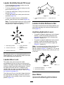
Reference Bar
When driving the traction unit, use the reference bar
as a handle and a leverage point for controlling the
traction control and the auxiliary-hydraulics lever . T o
ensure smooth, controlled operation, do not take
both hands of f the reference bar while operating the
machine.
9

T raction Control
g008128
Figure 5
1. Reference bar
2. T raction control
•T o move forward, move the traction control forward
(Figure 6 ).
g008129
Figure 6
•T o move rearward, move the traction control
rearward ( Figure 7 ).
Important: When reversing, look behind you
for obstructions and keep your hands on the
reference bar .
g008130
Figure 7
•T o turn right, rotate the traction control clockwise
(Figure 8 ).
g008131
Figure 8
•T o turn left, rotate the traction control
counterclockwise ( Figure 9 ).
g008132
Figure 9
•T o stop the machine, release the traction control
(Figure 5 ).
Note: The farther you move the traction control in
any direction, the faster the machine moves in that
direction.
10

Loader Arm/Attachment-T ilt Lever
•T o tilt the attachment forward, slowly move the
lever to the right ( Figure 10 ).
•T o tilt the attachment rearward, slowly move the
lever to the left ( Figure 10 ).
•T o lower the loader arms, slowly move the lever
forward ( Figure 10 ).
•T o raise the loader arms, slowly move the lever
rearward ( Figure 10 ).
•T o lower the loader arms to a detent (oat)
position, push the lever fully forward ( Figure 10 ).
Note: This allows attachments such as the leveler
and the hydraulic blade to follow the contours of
the ground (i.e., oat) when grading.
g029293
Figure 10
1. Detent (oat) position
4. T ilt the attachment
rearward.
2. Lower the loader arms. 5. T ilt the attachment
forward.
3. Raise the loader arms.
By moving the lever to an intermediate position (e.g.,
forward and left), you can move the loader arms and
tilt the attachment at the same time.
Loader-V alve Lock
The loader-valve lock secures the loader
arm/attachment-tilt lever so that you cannot push it
forward. This helps to ensure that no one accidentally
lowers the loader arms during maintenance. Secure
the loader valve with the lock, in addition to the
cylinder locks, any time you need to shut of f the
machine with the loader arms raised. Refer to Using
the Cylinder Lock ( page 23 ) .
T o set the lock, lift up on it so that it clears the hole in
the control panel and swing it to the left, in front of
the loader-arm lever , pushing it down into the locked
position ( Figure 1 1 ).
g029981
Figure 1 1
1. Loader arm/attachment-tilt
lever
2. Loader-valve lock
Loader-Control-Reference Bar
The loader-control-reference bar helps stabilize your
hand while operating the loader arm/attachment-tilt
lever ( Figure 3 ).
Auxiliary-Hydraulics Lever
•T o operate a hydraulic attachment in the forward
direction, rotate the auxiliary-hydraulics lever
rearward and pull it down to the reference bar
(Figure 12 , number 1).
•T o operate a hydraulic attachment in the reverse
direction, rotate the auxiliary-hydraulics lever
rearward, then move it left into the upper slot
(Figure 12 , number 2).
Note: If you release the lever while in the F ORWARD
position, the lever automatically returns to the
NEUTRAL position ( Figure 12 , number 3). If it is in the
REVERSE position, it remains there until you pull it out
of the slot.
g004179
Figure 12
1. Forward-ow hydraulics
3. Neutral
2. Reverse-ow hydraulics
Hour Meter
The hour meter displays the number of hours of
operation that have been logged on the machine.
1 1

Parking-Brake Lever
•T o engage the parking brake, push the lever
forward and to the left and then pull it rearward
(Figure 13 ).
Note: The traction unit may roll slightly before the
brakes engage in the drive sprocket.
•T o release the brake, push the lever forward and
then right, into the notch ( Figure 13 ).
g005552
Figure 13
Fuel Gauge
This gauge measures the amount of fuel in the fuel
tank(s).
Engine-Oil Pressure Light
If the engine-oil pressure gets too low , this light
illuminates and an audible alarm sounds. If this
happens, shut of f the engine immediately and check
the oil level. If it is low , add oil and look for possible
leaks.
g004350
Figure 14
1. Engine-oil pressure light 4. Battery-charge indicator
light
2. Engine-coolant
temperature light
5. Glow-plug light
3. Glow-plug switch
Battery-Charge Indicator Light
If the battery charge becomes too low , this light
illuminates and an audible alarm sounds. If this
happens, shut of f the engine and charge or replace
the battery . Check the tension of the alternator belt;
refer to your engine owner ’ s manual.
Engine-Coolant T emperature Light
If the engine coolant gets too hot, this light illuminates
and an audible alarm sounds. If this happens, shut of f
the engine and allow the traction unit to cool. Check
the coolant level when the engine has fully cooled.
Glow-Plug Light
This light illuminates while the glow plugs are charged
and warming the engine.
Glow-Plug Switch
Press and hold this switch for 10 seconds to activate
the glow plugs before starting the engine.
12

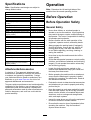
Specications
Note: Specications and design are subject to
change without notice.
Model 22323
Width
86 cm (34 inches)
Length
180 cm (71 inches)
Height
1 17 cm (46 inches)
W eight
864 kg (1,904 lb)
Operating capacity (with standard
bucket)
251 kg (553 lb)
T ipping capacity (with standard bucket) 717 kg (1,580 lb)
Wheelbase
79 cm (31 inches)
Dump height (with narrow bucket) 1 19 cm (47 inches)
Reach—fully raised (with narrow bucket) 55 cm (22 inches)
Height to hinge pin (narrow bucket in
highest position)
168 cm (66 inches)
Model 22324
Width
104 cm (41 inches)
Length
180 cm (71 inches)
Height
109 cm (43 inches)
W eight
913 kg (2,013 lb)
Operating capacity (with standard
bucket)
251 kg (553 lb)
T ipping capacity (with standard bucket) 717 kg (1,580 lb)
Wheelbase
79 cm (31 inches)
Dump height (with narrow bucket) 1 19 cm (47 inches)
Reach—fully raised (with narrow bucket) 55 cm (22 inches)
Height to hinge pin (narrow bucket in
highest position)
168 cm (66 inches)
Attachments/Accessories
A selection of T oro approved attachments and
accessories is available for use with the machine
to enhance and expand its capabilities. Contact
your Authorized Service Dealer or authorized T oro
distributor or go to www .T oro.com for a list of all
approved attachments and accessories.
T o ensure optimum performance and continued safety
certication of the machine, use only genuine T oro
replacement parts and accessories. Replacement
parts and accessories made by other manufacturers
could be dangerous, and such use could void the
product warranty .
Operation
Note: Determine the left and right sides of the
machine from the normal operating position.
Before Operation
Before Operation Safety
General Safety
•Never allow children or untrained people to
operate or service the machine. Local regulations
may restrict the age or require certied training of
the operator . The owner is responsible for training
all operators and mechanics.
•Become familiar with the safe operation of the
equipment, operator controls, and safety decals.
•Always engage the parking brake (if equipped),
shut of f the engine, remove the key , wait for all
moving parts to stop, and allow the machine
to cool before adjusting, servicing, cleaning, or
storing the machine.
•Know how to stop the machine and shut of f the
engine quickly .
•Check that the operator's presence controls, safety
switches, and shields are attached and functioning
properly . Do not operate the machine unless they
are functioning properly .
•Locate the pinch-point areas marked on the
machine and attachments; keep your hands and
feet away from these areas.
•Before operating the machine with an attachment,
ensure that the attachment is properly installed
and that it is a genuine T oro attachment. Read all
the attachment manuals.
•Evaluate the terrain to determine what accessories
and attachments you need to properly and safely
perform the job.
•Have the property or work area marked for buried
lines and other objects, and do not dig in marked
areas; note the location of unmarked objects and
structures, such as underground storage tanks,
wells, and septic systems.
•Inspect the area where you will use the equipment
for uneven surfaces or hidden hazards.
•Ensure that the area is clear of bystanders before
operating the machine. Stop the machine if
anyone enters the area.
13

Fuel Safety
•Use extreme care when handling fuel. It is
ammable and its vapors are explosive.
•Extinguish all cigarettes, cigars, pipes, and other
sources of ignition.
•Use only an approved fuel container .
•Do not remove the fuel cap or ll the fuel tank
while the engine is running or hot.
•Do not add or drain fuel in an enclosed space.
•Do not store the machine or fuel container where
there is an open ame, spark, or pilot light, such
as on a water heater or other appliance.
•If you spill fuel, do not attempt to start the engine;
avoid creating any source of ignition until the fuel
vapors have dissipated.
•T o prevent a static charge from igniting the fuel,
remove the machine from the truck or trailer and
refuel it on the ground, away from all vehicles. If
this is not possible, place a portable fuel container
on the ground, away from all vehicles, and ll it;
then refuel the machine from the fuel container
rather than from a fuel-dispenser nozzle.
•Keep the fuel-dispenser nozzle in contact with
the rim of the fuel tank or container opening at
all times until fueling is complete. Do not use a
nozzle lock-open device.
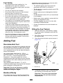
Adding Fuel
Recommended Fuel
Use only clean, fresh diesel fuel or biodiesel fuels with
low (<500 ppm) or ultra low (<15 ppm) sulfur content.
The minimum cetane rating should be 40. Purchase
fuel in quantities that you can use within 180 days to
ensure fuel freshness.
Use summer-grade diesel fuel (No. 2-D) at
temperatures above -7°C (20°F) and winter grade
(No. 1-D or No. 1-D/2-D blend) below that
temperature. Using winter-grade fuel at lower
temperatures provides lower ash point and cold ow
characteristics, which eases starting and reduces fuel
lter plugging.
Using summer-grade fuel above -7°C (20°F)
contributes toward longer fuel pump life and increased
power compared to winter-grade fuel.
Important: Do not use kerosene or gasoline
instead of diesel fuel. Failure to observe this
caution will damage the engine.
Biodiesel Ready
This machine can also use a biodiesel blended fuel
of up to B20 (20% biodiesel, 80% petrodiesel). The
petrodiesel portion should be low or ultra low sulfur .
Observe the following precautions:
•The biodiesel portion of the fuel must meet
specication ASTM D6751 or EN14214.
•The blended fuel composition should meet ASTM
D975 or EN590.
•Painted surfaces may be damaged by biodiesel
blends.
•Use B5 (biodiesel content of 5%) or lesser blends
in cold weather .
•Monitor seals, hoses, gaskets in contact with fuel
as they may degrade over time.
•Fuel lter plugging may occur for a time after
converting to biodiesel blends.
•Contact your distributor for more information on
biodiesel.
Filling the Fuel T ank(s)
1. Park the machine on a level surface, engage
the parking brake (if equipped), and lower the
loader arms.
2. Shut of f the engine, remove the key , and allow
the engine to cool.
3. Clean around the fuel-tank cap and remove it
(Figure 15 ).
g004231
Figure 15
1. Fuel-tank cap
4. Fill the tank to about 2.5 cm (1 inch) below the
top of the tank, not the ller neck, with fuel.
Important: This space in the tank allows
fuel to expand. Do not ll the fuel tank
completely full.
14

5. Install the fuel-tank cap securely , turning it until
it clicks.
6. Wipe up any spilled fuel.
Performing Daily
Maintenance
Before starting the machine each day , perform the
Each Use/Daily procedures listed in the Maintenance
( page 22 ) .
Important: Check the hydraulic-uid level
and bleed the fuel system before starting the
engine for the rst time; refer to Checking the
Hydraulic-Fluid Level ( page 43 ) and Bleeding the
Fuel System ( page 30 ) .
During Operation
During Operation Safety
General Safety
•Do not exceed the rated operating capacity , as the
machine may become unstable, which may result
in loss of control.
•Do not carry a load with the arms raised. Always
carry loads close to the ground.
•Use only T oro-approved attachments and
accessories. Attachments can change the stability
and the operating characteristics of the machine.
•For machines with a platform:
– Lower the loader arms before stepping of f the
platform.
– Do not try to stabilize the machine by putting
your foot on the ground. If you lose control of
the machine, step of f the platform and away
from the machine.
– Do not place your feet under the platform.
– Do not move the machine unless you are
standing with both feet on the platform and your
hands are holding onto the reference bars.
•Use your full attention while operating the
machine. Do not engage in any activity that
causes distractions; otherwise, injury or property
damage may occur .
•Look behind and down before backing up to
ensure that the path is clear .
•Never jerk the controls; use a steady motion.
•The owner/user can prevent and is responsible
for accidents that may cause personal injury or
property damage.
•W ear appropriate clothing including gloves, eye
protection, long pants, substantial slip-resistant
footwear , and hearing protection. T ie back long
hair and do not wear loose clothing or loose
jewelry .
•Do not operate the machine when you are tired, ill,
or under the inuence of alcohol or drugs.
•Never carry passengers and keep pets and
bystanders away from the machine.
•Operate the machine only in good light, keeping
away from holes and hidden hazards.
•Ensure that all the drives are in neutral and engage
the parking brake (if equipped) before starting the
engine. Start the engine only from the operator's
position.
•Use care when approaching blind corners, shrubs,
trees, or other objects that may obscure vision.
•Slow down and use caution when making turns
and crossing roads and sidewalks. W atch for
traf c.
•Stop the attachment when you are not working.
•Stop the machine, shut of f the engine, remove
the key , and inspect the machine if you strike
an object. Make any necessary repairs before
resuming operation.
•Never run an engine in an enclosed area.
•Never leave a running machine unattended.
•Before leaving the operating position, do the
following:
– Park the machine on a level surface.
– Lower the loader arms and disengage the
auxiliary hydraulics.
– Engage the parking brake (if equipped).
– Shut of f the engine and remove the key .
•Do not operate the machine when there is the risk
of lightning.
•Operate the machine only in areas where there is
suf cient clearance for you to safely maneuver .
Be aware of obstacles in close proximity to you.
Failure to maintain adequate distance from trees,
walls, and other barriers may result in injury as the
machine backs up during operation if you are not
attentive to the surroundings.
•Check for overhead clearance (i.e., electrical
wires, branches, and doorways) before driving
under any objects and do not contact them.
•Do not overll the attachment and always keep the
load level when raising the loader arms. Items in
the attachment could fall and cause injury .
Slope Safety
•Operate the machine up and down slopes with
the heavy end of the machine uphill. W eight
15

distribution changes with attachments. An empty
bucket makes the rear of the machine the heavy
end, and a full bucket makes the front of the
machine the heavy end. Most other attachments
make the front of machine the heavy end.
•Raising the loader arms on a slope af fects the
stability of the machine. Keep the loader arms in
the lowered position when on slopes.
•Slopes are a major factor related to loss of control
and tip-over accidents, which can result in severe
injury or death. Operating the machine on any
slope or uneven terrain requires extra caution.
•Establish your own procedures and rules for
operating on slopes. These procedures must
include surveying the site to determine which
slopes are safe for machine operation. Always
use common sense and good judgment when
performing this survey .
•Slow down and use extra care on hillsides. Ground
conditions can af fect the stability of the machine.
•A void starting or stopping on a slope. If the
machine loses traction, proceed slowly , straight
down the slope.
•A void turning on slopes. If you must turn, turn
slowly and keep the heavy end of the machine
uphill.
•Keep all movements on slopes slow and gradual.
Do not make sudden changes in speed or
direction.
•If you feel uneasy operating the machine on a
slope, do not do it.
•W atch for holes, ruts, or bumps, as uneven terrain
could overturn the machine. T all grass can hide
obstacles.
•Use caution when operating on wet surfaces.
Reduced traction could cause sliding.
•Evaluate the area to ensure that the ground is
stable enough to support the machine.
•Use caution when operating the machine near the
following:
– Drop-of fs
– Ditches
– Embankments
– Bodies of water
The machine could suddenly roll over if a track
goes over the edge or the edge caves in. Maintain
a safe distance between the machine and any
hazard.
•Do not remove or add attachments on a slope.
•Do not park the machine on a hillside or slope.
Utility Line Safety
•If you strike a utility line, do the following:
– Shut of f the machine and remove the key .
– Remove all individuals from the work area.
– Immediately contact the proper emergency and
utility authorities to secure the area.
– If you damage a ber-optic cable, do not look
into the exposed light.
•Do not leave the operator ’ s platform if the machine
is charged with electricity . Y ou will be safe as long
as you do not leave the platform.
– T ouching any part of the machine may ground
you.
– Do not allow another individual to touch or
approach the machine when charged.
– Always assume the machine is charged if you
strike an electrical or communication line. Do
not attempt to leave the machine.
•Leaking gas is both ammable and explosive and
may cause serious injury or death. Do not smoke
while operating the machine.
Starting the Engine
1. Ensure that the auxiliary hydraulics lever is in
the N EUTRAL position.
2. Move the throttle lever midway between S LOW
and F AST positions.
3. Insert the key into the key switch and turn it to
the R UN position.
4. Press the glow-plug switch and hold it for 10
seconds.
5. T urn the key to the S TART position. When the
engines starts, release the key .
Important: Do not engage the starter for
more than 10 seconds at a time. If the engine
fails to start, wait 30 seconds for the starter
to cool down between attempts. Failure to
follow these instructions could burn out the
starter motor .
6. Move the throttle lever to the F AST position.
Important: Running the engine at high
speeds when the hydraulic system is cold
(i.e., when the air temperature is at or
below freezing) could damage the hydraulic
system. When starting the engine in cold
conditions, allow it to run in the middle
throttle position for 2 to 5 minutes before
moving the throttle to the F AST position.
Note: If outdoor temperature is below freezing,
store the traction unit in a garage to keep it
warmer and to aid in starting.
16

Driving the Machine
Use the traction control to move the machine. The
farther you move the traction control in any direction,
the faster the machine moves in that direction.
Release the traction control to stop the machine.
The throttle control regulates the engine speed as
measured in rpm (revolutions per minute). Place the
throttle lever in the F AST position for best performance.
Y ou can, however , use the throttle position to operate
at slower speeds.
Shutting Off the Engine
1. Park the machine on a level surface, engage
the parking brake (if equipped), and lower the
loader arms.
2. Ensure that the auxiliary hydraulics lever is in
the N EUTRAL position.
3. Move the throttle lever to the S LOW position.
4. If the engine has been working hard or is hot, let
it idle for a minute before turning the key switch
to the O FF position.
Note: This helps to cool the engine before you
shut it of f. In an emergency , you can shut of f
the engine immediately .
5. T urn the key switch to the O FF position and
remove the key .
CAUTION
A child or untrained bystander could attempt
to operate the traction unit and be injured.
Remove the key from the key switch when
leaving the traction unit, even if just for a few
seconds.
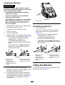
Using Attachments
Installing an Attachment
Important: Use only T oro-approved attachments.
Attachments can change the stability and the
operating characteristics of the machine. The
warranty of the machine may be voided if you use
the machine with unapproved attachments.
Important: Before installing the attachment,
ensure that the mount plates are free of any dirt or
debris and that the pins rotate freely . If the pins
do not rotate freely , grease them.
1. Position the attachment on a level surface with
enough space behind it to accommodate the
machine.
2. Start the engine.
3. T ilt the attachment mount plate forward.
4. Position the mount plate into the upper lip of the
attachment receiver plate ( Figure 16 ).
17

g003710
Figure 16
1. Mount plate 2. Receiver plate
5. Raise the loader arms while tilting back the
mount plate at the same time.
Important: Raise the attachment enough to
clear the ground and tilt the mount plate all
the way back.
6. Shut of f the engine and remove the key .
7. Engage the quick-attach pins, ensuring that they
are fully seated in the mount plate ( Figure 17 ).
Important: If the pins do not rotate to the
engaged position, the mount plate is not
fully aligned with the holes in the attachment
receiver plate. Check the receiver plate and
clean it if necessary .
g00371 1
Figure 17
1. Quick-attach pins
(engaged position)
3. Engaged position
2. Disengaged position
W ARNING
If you do not fully seat the quick-attach
pins through the attachment mount plate,
the attachment could fall off the machine,
crushing you or bystanders.
Ensure that the quick-attach pins are fully
seated in the attachment mount plate.
18

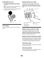
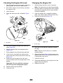
Connecting the Hydraulic Hoses
W ARNING
Hydraulic uid escaping under pressure can
penetrate skin and cause injury . Fluid injected
into the skin must be surgically removed
within a few hours by a doctor familiar with
this form of injury; otherwise, gangrene may
result.
• Ensure that all hydraulic-uid hoses
and lines are in good condition and all
hydraulic connections and ttings are tight
before applying pressure to the hydraulic
system.
• Keep your body and hands away from
pinhole leaks or nozzles that eject
high-pressure hydraulic uid.
• Use cardboard or paper to nd hydraulic
leaks; never use your hands.
CAUTION
Hydraulic couplers, hydraulic lines/valves,
and hydraulic uid may be hot. If you contact
hot components, you may be burned.
• W ear gloves when operating the hydraulic
couplers.
• Allow the machine to cool before touching
hydraulic components.
• Do not touch hydraulic uid spills.
If the attachment requires hydraulics for operation,
connect the hydraulic hoses as follows:
1. Shut of f the engine and remove the key .
2. Move the auxiliary-hydraulics lever forward,
backward, and back to the N EUTRAL position to
relieve pressure at the hydraulic couplers.
3. Remove the protective covers from the hydraulic
connectors on the machine.
4. Ensure that all foreign matter is cleaned from
the hydraulic connectors.
5. Push the attachment male connector into the
female connector on the machine.
Note: When you connect the attachment male
connector rst, you relieve any pressure built
up in the attachment.
6. Push the attachment female connector onto the
male connector on the machine.
7. Conrm that the connection is secure by pulling
on the hoses.
Removing an Attachment
1. Park the machine on a level surface.
2. Lower the attachment to the ground.
3. Shut of f the engine and remove the key .
4. Disengage the quick-attach pins by turning them
to the outside.
5. If the attachment uses hydraulics, move the
auxiliary-hydraulics lever forward, backward,
and back to the N EUTRAL position to relieve
pressure at the hydraulic couplers.
6. If the attachment uses hydraulics, slide the
collars back on the hydraulic couplers and
disconnect them.
Important: Connect the attachment hoses
together to prevent hydraulic system
contamination during storage.
7. Install the protective covers onto the hydraulic
couplers on the machine.
8. Start the engine, tilt the mount plate forward, and
back the machine away from the attachment.
After Operation
After Operation Safety
General Safety
•Engage the parking brake (if equipped), lower
the loader arms, shut of f the engine, remove the
key , wait for all movement to stop, and allow the
machine to cool before adjusting, cleaning, storing,
or servicing it.
•Clean debris from the attachments, drives,
muf ers, and engine to help prevent res. Clean
up oil or fuel spills.
•Keep all parts in good working condition and all
hardware tightened.
•Do not touch parts that may be hot from operation.
Allow them to cool before attempting to maintain,
adjust, or service the machine.
•Use care when loading or unloading the machine
into a trailer or truck.
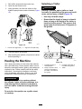
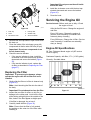
Moving a Non-Functioning
Machine
Important: Do not tow or pull the machine
without rst opening the tow valves, or you will
damage the hydraulic system.
19

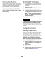
1. Shut of f the engine and remove the key .
2. Open the rear-access cover .
3. Using a wrench, turn the tow valves on the
hydraulic pumps twice counter-clockwise ( Figure
18 ).
g004181
Figure 18
1. Left tow valve (right track) 2. Right tow valve (left track)
4. T ow the machine as required.
5. After repairing the machine, close the tow valves
before operating it.
Hauling the Machine
Use a heavy-duty trailer or truck to haul the machine.
Use a full-width ramp. Ensure that the trailer or truck
has all the necessary brakes, lighting, and marking as
required by law . Please carefully read all the safety
instructions. Knowing this information could help
you or bystanders avoid injury . Refer to your local
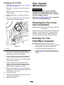
ordinances for trailer and tie-down requirements.
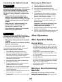
W ARNING
Driving on the street or roadway without
turn signals, lights, reective markings, or a
slow-moving-vehicle emblem is dangerous
and can lead to accidents causing personal
injury .
Do not drive the machine on a public street
or roadway .
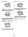
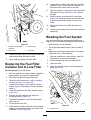
Selecting a T railer
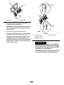
W ARNING
Loading a machine onto a trailer or truck
increases the possibility of tip-over and could
cause serious injury or death ( Figure 19 ).
• Use only full-width ramps.
• Ensure that the length of ramp is at least 4
times as long as the height of the trailer or
truck bed to the ground. This ensures that
ramp angle does not exceed 15 degrees on
at ground.
g229507
Figure 19
1. Full-width ramp(s) in
stowed position
3. H=height of the trailer or
truck bed to the ground
2. Ramp is at least 4 times
as long as the height of
the trailer or truck bed to
the ground
4. T railer
20
Page is loading ...
Page is loading ...
Page is loading ...
Page is loading ...
Page is loading ...
Page is loading ...
Page is loading ...
Page is loading ...
Page is loading ...
Page is loading ...
Page is loading ...
Page is loading ...
Page is loading ...
Page is loading ...
Page is loading ...
Page is loading ...
Page is loading ...
Page is loading ...
Page is loading ...
Page is loading ...
Page is loading ...
Page is loading ...
Page is loading ...
Page is loading ...
Page is loading ...
Page is loading ...
Page is loading ...
Page is loading ...
Page is loading ...
Page is loading ...
Page is loading ...
Page is loading ...
-
 1
1
-
 2
2
-
 3
3
-
 4
4
-
 5
5
-
 6
6
-
 7
7
-
 8
8
-
 9
9
-
 10
10
-
 11
11
-
 12
12
-
 13
13
-
 14
14
-
 15
15
-
 16
16
-
 17
17
-
 18
18
-
 19
19
-
 20
20
-
 21
21
-
 22
22
-
 23
23
-
 24
24
-
 25
25
-
 26
26
-
 27
27
-
 28
28
-
 29
29
-
 30
30
-
 31
31
-
 32
32
-
 33
33
-
 34
34
-
 35
35
-
 36
36
-
 37
37
-
 38
38
-
 39
39
-
 40
40
-
 41
41
-
 42
42
-
 43
43
-
 44
44
-
 45
45
-
 46
46
-
 47
47
-
 48
48
-
 49
49
-
 50
50
-
 51
51
-
 52
52


Toro Dingo TX 525 Wide Track User manual
- Type
- User manual
- This manual is also suitable for
Ask a question and I''ll find the answer in the document
Finding information in a document is now easier with AI