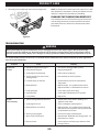
Troy-Bilt 13APA1BNA66 User manual
- Category
- Lawnmowers
- Type
- User manual
This manual is also suitable for

Safe Operation Practices • Set-Up • Operation • Product Care
OperatOr’s Manual
Front Engine Lawn Tractor
NOTE: This Operator’s Manual covers several models. Features may vary by model. Not all features in this manual are
applicable to all models and the model depicted may differ from yours.
Record Product Information
Before setting up and operating your new equipment,
please locate the model plate on the equipment and
record the information in the provided area to the right.
You can locate the model plate by lifting up the seat
and looking under the seat pan. This information will be
necessary, should you seek technical support via our web
site or with your local authorized service dealer.
Model Number
Serial Number
English ............................................................................................................................Page 1
Spanish (Español) ..........................................................................................................Page 37
French (Français) ...........................................................................................................Page 75
Form No. 769-25738E
(June 20, 2023)
WARNING
Read and follow all safety rules and instructions in this manual before attempting to operate this machine.
Failure to comply with these instructions may result in personal injury - SAVE THESE INSTRUCTIONS.
WARNING
CALIFORNIA PROPOSITION 65
Engine Exhaust, some of its constituents, and certain vehicle components contain or emit chemicals known to the State of
California to cause cancer and birth defects or other reproductive harm.
Battery posts, terminals, and related accessories contain lead and lead compounds, chemicals known to the State of
California to cause cancer and reproductive harm. Wash hands after handling. www.p65warnings.ca.gov

2
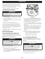
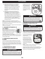
PREPARATION BEFORE OPERATING
1. Thoroughly inspect the area where the tractor is to be used.
Remove all stones, sticks, wire, bones, toys, and other foreign
objects which could be picked up and thrown by the blade(s).
Thrown objects can cause serious personal injury.
2. To help avoid blade contact or a thrown object injury, keep
helpers at least 75 feet (23 meters) from the tractor while it
is in operation. Keep bystanders, children, and pets inside
during operation. Stop tractor if anyone enters the area.
3. Be aware of the tractor discharge direction and do not point
it at anyone.
OPERATING
1. Data indicates that operators, age 65 years and above, are
involved in a large percentage of tractor-related injuries.
These operators should evaluate their ability to operate the
tractor safely enough to protect themselves and others from
serious injury.
2. Disengage the blades and set the parking brake before
attempting to start the tractor.
3. Do not put hands or feet near rotating parts or under the
cutting deck. Contact with the blade(s) can amputate hands
and feet.
4. Watch for holes, ruts, bumps, rocks, or other hidden objects.
Uneven terrain could overturn the tractor. Tall grass can
hide obstacles.
5. Plan your mowing pattern to avoid discharge of material
toward roads, sidewalks, helpers, and the like. Avoid
discharging material against a wall or obstruction which
may cause discharged material to ricochet back toward
the operator.
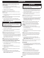
SAFE OPERATION PRACTICES
WARNING
This symbol points out important safety instructions which, if not followed, could endanger the personal
safety and/or property of yourself and others. Read and follow all instructions in this manual before
attempting to operate this machine. Failure to comply with these instructions may result in personal injury.
When you see this symbol, HEED ITS WARNING!
DANGER
This machine was built to be operated according to the safe operation practices in this manual. As with any type of
power equipment, carelessness or error on the part of the operator can result in serious injury. This machine is capable
of amputating hands and feet and throwing objects. Failure to observe the following safety instructions could result in
serious injury or death.
GENERAL OPERATION
1. Read, understand, and follow all instructions on the tractor
and in the manual(s) before attempting to assemble and
operate. Keep this manual in a safe place for future and
regular reference and for ordering replacement parts.
2. Be familiar with all controls and their proper operation. Know
how to stop the tractor and disengage them quickly.
3. Never allow children under 14 years of age to operate this
tractor. Children 14 and over should read and understand
the instructions and safe operation practices in this manual
and on the tractor and should be trained and supervised by
an adult.
4. Never allow adults to operate this tractor without
proper instruction.
5. If situations occur which are not covered in this manual, use
care and good judgment. Contact your customer service
representative for assistance.
6. According to the U.S. Consumer Products Safety Commission
(CPSC) and the U.S. Environmental Protection Agency (EPA),
this product has an estimated useful life of seven (7) years,
under ordinary use conditions. At the end of its useful life,
have the product inspected annually to ensure all mechanical
and safety systems are operating properly, safely, and are
not worn excessively. Failure to do so may result in accident,
injury, or death.
4. Always wear safety glasses or safety goggles during
operation and while performing an adjustment or repair to
protect your eyes. Thrown objects which ricochet can cause
serious injury to the eyes.
5. Wear sturdy, rough-soled work shoes and close-fitting slacks
and shirts. Loose-fitting clothes, jewelry, and long hair can
be caught in moving parts. Never operate this tractor in bare
feet or sandals.
6. Never overfill fuel tank. Fill tank to no more than 1/2 inch
(13 mm) below bottom of filler neck to allow space for
fuel expansion.
7. Replace gasoline cap and tighten securely.
8. Use only accessories and attachments approved for this
tractor by the tractor manufacturer. Read, understand, and
follow all instructions provided with the approved accessory
or attachment.

3
SAFE OPERATION PRACTICES
6. Check overhead clearances carefully before driving under
low hanging tree branches, wires, door openings, etc., where
the operator may be struck or pulled from the tractor, which
could result in serious injury.
7. Never leave a running tractor unattended. Always turn off
blade(s), set the parking brake, stop the engine, and remove
the key before dismounting.
8. Disengage blade(s), set the parking brake, stop engine,
and wait until the blade(s) come to a complete stop before
removing grass catcher, emptying grass, unclogging chute,
removing any grass or debris, or making any adjustments.
9. Your tractor is designed to cut normal residential grass of a
height no more than 10 inches (25 cm). Do not attempt to
mow through unusually tall, dry grass (e.g. pasture) or piles
of dry leaves. Dry grass or leaves may contact the engine
exhaust and/or build up on the tractor deck presenting a
potential fire hazard.
10. Back up slowly. Always look down and behind before and
while backing to avoid a back-over accident.
11. Never carry passengers.
12. Stay at least 10 feet (3 meters) from drop-offs, ditches,
embankments, or the edge of water. The tractor could
suddenly turn over if a wheel is over the edge of a cliff, ditch,
or if an edge caves in.
13. A missing or damaged chute deflector can cause blade
contact or thrown object injuries.
14. Do not operate the tractor without the chute deflector or
entire grass catcher in its proper place.
15. Use extra care with grass catchers or other attachments.
These can change the stability of the tractor. Always follow
the attachment manufacturer’s instructions.
16. Stop the blades when crossing gravel drives, walks, or roads
and while not cutting grass.
17. Watch for traffic when operating near or crossing roadways.
This tractor is not intended for use on any public roadway.
18. Mow only in daylight or good artificial light.
19. Do not operate the tractor while under the influence of
alcohol or drugs.
20. Slow down before turning. Operate the tractor smoothly.
Avoid erratic operation and excessive speed.
21. The muffler and engine become very hot and can cause
serious burn injuries. Do not touch. Allow the tractor to cool
for five minutes before attempting any service.
22. Never run an engine indoors or in a poorly ventilated area.
Engine exhaust contains carbon monoxide, an odorless and
deadly gas.
CHILDREN
1. Tragic accidents can occur if the operator is not alert to the
presence of children. Children are often attracted to the
tractor and the mowing activity. They do not understand the
dangers. Never assume that children will remain where you
last saw them.
2. Keep bystanders, children, and pets inside during operation
under the watchful care of a responsible adult other than the
operator. Stop tractor if anyone enters the area.
3. Never carry children, even with the blade(s) shut off. They
may fall off or interfere with safe tractor operation, causing
serious injury or death.
4. Children who have been given rides in the past could
suddenly appear in the mowing area for another ride and be
run over or backed over by the tractor, causing serious injury
or death.
5. Be alert and turn tractor off if a child or bystander enters
the area.
6. To avoid back-over accidents, always look behind and down
for small children.
7. Use extreme care when approaching blind corners, doorways,
shrubs, trees, or other objects that may block your vision of a
child who may run into the path of the tractor.
8. Never allow children under 14 years of age to operate this
tractor. Children 14 and over should read and understand
the instructions and safe operation practices in this manual
and on the tractor and should be trained and supervised by
an adult.
9. Do not allow any child to joyride on the tractor. The tractor is
not a toy or a go-cart. Warn children that the tractor can be
dangerous and they must stay away from it at all times.
10. Keep children away from hot or running engines. They can
suffer burns from a hot muffler.
11. Remove key when tractor is unattended to prevent
unauthorized operation. Make certain the key is inaccessible
to small children.
SLOPE OPERATION
1. Slopes are a major factor related to loss of control and tip-
over accidents which can result in severe injury or death. All
slopes require extra caution. If you cannot back up the slope
or if you feel uneasy on it, do not mow it.
2. For your safety, measure any slope before using the tractor
on the sloped area. Use a slope measuring device in addition
to the slope gauge included as part of this manual to measure
slopes before operating this tractor on a sloped or hilly area.
Smart phone applications can also be utilized to measure
slopes. If the slope is greater than 15° (25%) as shown on the
slope gauge or a slope measuring device, do not operate this
tractor on that area or serious injury could result.

4
SAFE OPERATION PRACTICES
FIRE AND FUEL
1. To avoid personal injury or property damage use extreme
care in handling gasoline. Gasoline is extremely flammable
and the vapors are explosive. Serious personal injury
can occur when gasoline is spilled on yourself or your
clothes, which can ignite. Wash your skin and change
clothes immediately.
2. Extinguish all cigarettes, cigars, pipes, and other sources
of ignition.
3. Use only an approved gasoline container.
4. Never remove gas cap or add fuel while the engine is hot
or running. Allow engine to cool at least five minutes
before refueling.
5. Never fuel tractor indoors.
6. Never store the tractor or fuel container inside where there is
an open flame, spark, or pilot light as on a water heater, space
heater, furnace, clothes dryer, or other gas appliances.
7. If gasoline is spilled, wipe it off the engine and equipment.
Clean up oil or fuel spillage and remove any fuel-soaked
debris. Move tractor to another area. Wait five minutes
before starting the engine.
8. To reduce fire hazards, keep tractor free of grass, leaves, or
other debris build-up. Follow the Post-Operation Tractor Care
instructions in the Product Care section.
9. The tractor is designed to cut normal residential grass of a
height no more than 10 inches (25 cm). Do not attempt to
mow through unusually tall, dry grass (e.g., pasture) or piles
of dry leaves. Dry grass or leaves may contact the engine
exhaust and/or build up on the tractor deck presenting a
potential fire hazard.
10. Never overfill fuel tank. Fill tank to no more than 1/2 inch
(13 mm) below bottom of filler neck to allow space for
fuel expansion.
11. Replace gasoline cap and tighten securely. Do not operate
without fuel cap in place.
12. Allow tractor to cool at least five minutes before fueling
or storing.
13. Never fill containers inside a vehicle or on a truck or trailer
bed with a plastic liner. Always place containers on the
ground away from your vehicle before filling.
14. When practical, remove gas-powered equipment from
the truck or trailer and refuel it on the ground. If this is
not possible, then refuel such equipment on a trailer
with a portable container, rather than from a gasoline
dispenser nozzle.
15. Keep the nozzle in contact with the rim of the fuel tank or
container opening at all times until fueling is complete. Do
not use a nozzle lock-open device.
3. Do not mow on slopes greater than 15° (25%).
4. Do not mow across slopes, only mow up and down slopes
that are less than 15° (25%). Use low speeds and avoid
sudden turns.
5. Do not mow on wet grass. Reduced traction could cause
sliding or a loss of control.
6. Do not operate tractor under any conditions where traction,
steering, or stability is in question. Tires could slide even if
the wheels are stopped.
7. Avoid starting and stopping on slopes. Avoid making
sudden changes in speed or direction. Make turns slowly
and gradually.
8. Use extra care while operating tractor with grass catcher
or other attachment(s). They can affect the stability of the
tractor. Do not use grass catcher on slopes greater than
10° (17%).
9. Do not try to stabilize the tractor by putting your foot on
the ground.
10. Keep all movement on slopes slow and gradual. Do not make
sudden changes in speed or direction. Rapid acceleration
could cause the front of the tractor to lift and rapidly roll over
backwards, which could cause serious injury or death.
11. Do not turn off tractor and freewheel downhill. Over-
speeding may cause the operator to lose control of the tractor
resulting in serious injury or death.
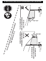
SLOPE GAUGE (BACK COVER)
WARNING
Slopes are a major factor related to slip and fall accidents
which can result in severe injury or death. All slopes
require extra caution. If you feel uneasy on the slope, do
not mow it. Do not mow on slopes greater than 15° (25%).
Do not mow across slopes, only mow up and down slopes.
USE THE SLOPE GAUGE ON THE BACK COVER AS SHOWN TO
DETERMINE IF A SLOPE IS TOO STEEP FOR SAFE OPERATION!
To check the slope, proceed as follows:
1. Open manual to the back cover and fold along the
dashed line.
2. Locate a vertical object on or behind the slope (e.g., a pole,
building, fence, tree, etc.).
3. Align either side of the slope gauge with the object.
4. Adjust gauge up or down until the left corner touches
the slope.
5. If there is a gap below the gauge, the slope is too steep for
safe operation.

5
SAFE OPERATION PRACTICES
5. Before cleaning, repairing, or inspecting, make certain the
blade(s) and all moving parts have stopped. Turn off the
engine, remove the key, and disconnect the spark plug wire(s)
and negative battery cable to prevent unintended starting.
6. Check to make sure the blades come to a complete stop in
not more than five seconds after disengaging the blade
disengagement control per the schedule shown on the
Maintenance Schedule chart in the Product Care section
of this manual. Measure the stopping time with a stop
watch. If the blades do not stop completely in less than five
seconds, the tractor should be serviced professionally by an
authorized dealer.
7. Check the safety interlock system for proper function per the
schedule shown on the Maintenance Schedule chart in the
Product Care section of this manual. If the safety interlock
system does not function properly, have the tractor serviced
professionally by an authorized dealer.
8. Never tamper with the safety interlock system or other safety
devices. Check their proper operation regularly.
9. Check the blade(s) and engine mounting bolt torque in
accordance with the Maintenance Schedule chart in this
manual. Also, visually inspect blade(s) for damage (e.g.,
excessive wear, bent, cracked). Replace the blade(s) with the
original equipment manufacturer’s (O.E.M.) blade(s) only.
10. Use of service parts which do not meet the original
equipment specifications may lead to improper performance
and compromise safety.
11. Keep all nuts, bolts, and screws tight to be sure the
equipment is in safe working condition. Review the
Maintenance Schedule chart in this manual for service
interval information.
12. After striking a foreign object, stop the engine, remove the
key, and disconnect the spark plug wire(s) and negative
battery cable to prevent unintended starting. Thoroughly
inspect the tractor for any damage. Repair the damage before
starting and operating.
13. Never attempt to make adjustments or repairs to the tractor
while the engine is running.
14. Grass catcher components and the chute deflector are subject
to wear and damage which could expose moving parts or
allow objects to be thrown. Frequently check components
and replace immediately with original equipment
manufacturer’s (O.E.M.) parts only.
15. Maintain or replace safety and instruction labels,
as necessary.
16. Observe proper disposal laws and regulations for gas, oil, etc.,
to protect the environment.
HAULING
1. Use properly secured full width ramps for loading and
unloading tractor for transport.
2. Use extra care when loading or unloading the tractor into a
trailer or truck. This tractor should not be driven up or down
ramp(s), because the tractor could tip over, causing serious
personal injury. The tractor must be pushed manually on
ramp(s) to load or unload properly.
3. Raise the deck to the highest position for loading clearance.
TOWING
1. Do not tow a load that exceeds 250 lbs (113 kg) rolling weight
and never exceed 50 lbs (22 kg) tongue weight.
2. Do not attach towed equipment except at the hitch point of
the tractor.
3. Never allow children or others in or on towed equipment.
4. Do not tow on slopes greater than 5° (9%). On slopes, the
weight of towed equipment may cause loss of traction, loss of
control, and/or the ability to stop.
5. Always use extra caution when towing with a tractor capable
of making tight turns (e.g. tight-turn tractor). Make wide
turns to avoid jack-knifing.
6. Travel slowly and allow extra distance to stop.
SERVICE
1. Keep machine in good working order. Do not use the tractor
until worn or damaged parts are replaced.
2. To avoid serious injury or death, do not modify engine in
any way. Tampering with the governor setting can lead to
a runaway engine and cause it to operate at unsafe speeds.
Never tamper with factory setting of engine governor. Do
not change the engine governor settings or over-speed the
engine. The governor controls the maximum safe operating
speed of the engine.
3. Tractor blades are sharp. Wrap the blade or wear gloves, and
use extra caution when servicing them.
4. Tractors with hydraulic pumps, hoses, or motors, and/or
diesel injection systems have fluid systems under pressure.
Fluid escaping under pressure may have sufficient force to
penetrate skin and cause serious injury. If fluid is injected into
the skin, seek immediate medical attention. Keep body and
hands away from pinholes or nozzles that eject fluid under
high pressure. If a leak occurs, have the tractor immediately
serviced by an authorized dealer.

6
SAFE OPERATION PRACTICES
NOTICE REGARDING EMISSIONS
Engines which are certified to comply with California and federal
EPA emission regulations for SORE (Small Off Road Equipment)
are certified to operate on regular unleaded gasoline and
may include the following emission control systems: Engine
Modification (EM) and Three Way Catalyst (TWC), if so equipped.
When required, models are equipped with low permeation fuel
lines and fuel tanks for evaporative emission control. California
models may also include a carbon canister. Please contact
Customer Support for information regarding the evaporative
emission control configuration for your model.
SPARK ARRESTOR
WARNING
This machine is equipped with an internal combustion
engine and should not be used on or near any
unimproved forest-covered, brush-covered, or grass-
covered land unless the engine’s exhaust system is
equipped with a spark arrestor meeting applicable local
or state laws (if any).
If a spark arrestor is used, it should be maintained in effective
working order by the operator. In the State of California the
above is required by law (Section 4442 of the California Public
Resources Code). Other states may have similar laws. Federal
laws apply on federal lands.
A spark arrestor for the muffler is available through your
nearest engine authorized service dealer, or contact the service
department, P.O. Box 361131, Cleveland, Ohio 44136-0019.
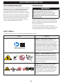
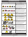
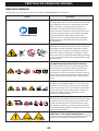
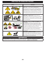
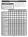
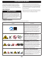
SAFETY SYMBOLS
This table depicts and describes safety symbols that MAY APPEAR on this product.
Symbol Description
OPESymbol.com
WARNING - READ OPERATOR’S MANUAL - Read,
understand, and follow all the safety rules and
instructions in the manual(s) and on the tractor before
attempting to operate this tractor. Failure to comply
with this information may result in personal injury or
death. Keep this manual in a safe location for future and
regular reference. Using a Smart Phone, scan the QR
code symbol to learn more information concerning the
warnings contained on this tractor. You can also go to
www.OPESymbol.com for more information.
WARNING - AVOID THROWN OBJECTS INJURY -
Keep helpers at least 75 feet (23 meters) from machine
during operation. Remove all stones, sticks, wire,
bones, toys, and other foreign objects which could be
picked up and thrown by the blade(s). Do not operate
the tractor without the discharge cover or entire grass
catcher in its proper place.
WARNING - AVOID CHILD BACKOVER/RUNOVER/
BLADE INJURY - To avoid back-over accidents,
always look behind and down for small children. Never
carry children, even with the blade(s) shut off. Keep
bystanders, children, and pets inside during operation
under the watchful care of a responsible adult other
than the operator. Stop tractor if anyone enters
the area.

7
SAFE OPERATION PRACTICES
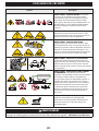
Symbol Description
>
10 ft
(3 m)
>
10 ft
(3 m)
WARNING - AVOID TIP-OVER/ROLL-OVER
INJURY - Do not operate machine on a slope greater
than 15° (25%). Do not mow across slopes, only mow
up and down slopes that are less than 15° (25%). Use
low speeds and avoid sudden turns on slopes. Stay
at least 10 feet (3 meters) from drop-offs, ditches,
embankments, or the edge of water.
>10i n (2 5c m)
WARNING - AVOID FIRES - Your tractor is designed to
cut normal residential grass of a height no more than
10 inches (25 cm). Do not attempt to mow through
unusually tall, dry grass (e.g., pasture) or piles of dry
leaves. Allow tractor to cool at least five minutes
before fueling or storing inside an enclosed garage or
storage shed.
WARNING - AVOID AMPUTATION INJURY - Do
not put hands or feet near or under the cutting deck.
Contact with the blade(s) can amputate hands and feet.
12
3
WARNING - AVOID AMPUTATION INJURY - Do not
put hands or feet near rotating parts or under the
cutting deck. Contact with the blade(s) can amputate
hands and feet. Ensure that all safety devices (guards,
shields, switches, etc.) are in place and working.
Belt and/or blade spindle contact can crush or injure
body parts.
WARNING - REMOVE KEY - Always turn off blade(s),
set the parking brake, stop engine, and remove key
before dismounting. If you are leaving the tractor
unattended, always remove the key to prevent
unauthorized use by children or others.
<5 0l b
(22k g) <2 50 lb (113 kg )
WARNING - AVOID TOWING RELATED INJURY - Do
not tow a load that exceeds 250 lbs (113 kg) rolling
weight and never exceed 50 lbs (22 kg) tongue
weight. Never allow children or others in or on towed
equipment. Do not tow on slopes greater than 5° (9%).
On slopes, the weight of the towed equipment may
cause loss of traction, loss of control, and/or loss of the
ability to stop. Travel slowly and allow extra distance
to stop.
WARNING - HOT SURFACE - The muffler and engine
become very hot and can cause serious burn injuries.
Do not touch. Allow the machine to cool for at least five
minutes before storing or attempting any service.
WARNING
Your Responsibility—Restrict the use of this power machine to persons who read, understand, and follow the warnings
and instructions in this manual and on the machine - SAVE THESE INSTRUCTIONS!

8
SET-UP
NOTE: This Operator’s Manual covers several models. Tractor
features may vary by model. Not all features in this manual are
applicable to all tractor models and the tractor depicted may
differ from yours.
NOTE: All references in this manual to the left or right side and
front or back of the tractor are from the operating position only.
Exceptions, if any, will be specified.
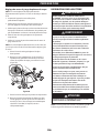
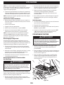
PREPARATION
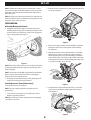
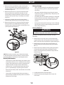
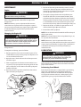
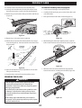
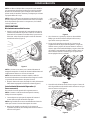
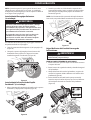
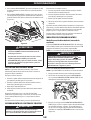
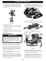
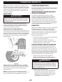
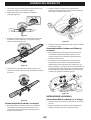
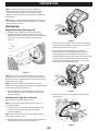
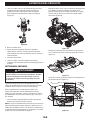
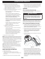
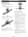
Manually Moving the Tractor
1. Engage the transmission bypass rod to move the tractor
manually without starting it. The transmission bypass rod is
located on the rear of the tractor, on the frame. Engage the
bypass rod by pulling out (Figure 1).
Figure 1
NOTE: If the tractor will not move or does not move freely when
pushing check if the hydrostatic bypass rod is fully open or the
brake is engaged.
NOTE: The transmission will NOT engage when the hydrostatic
bypass rod is pulled out. Return the rod to its disengaged
position prior to operating the tractor.
2. Disengage the transmission bypass rod by pushing the rod
back in after moving the tractor (Figure 1).
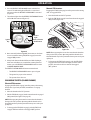
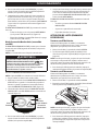
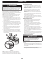
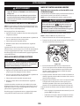
Install Operator’s Seat (if necessary)
To install the seat proceed as follows:
NOTE: The seat is shipped with the seat switch and seat
pan attached.
1. Cut any straps securing the seat assembly to the tractor.
Remove any packing material.
NOTE: Be careful not to cut the wiring harness connecting the
seat and the seat switch.
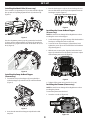
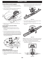
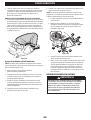
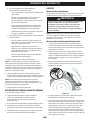
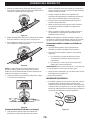
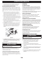
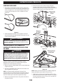
2. Remove the two shoulder bolts (a) and flange lock nuts (b) in
the seat pan (Figure 2).
a
abb
Figure 2
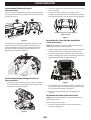
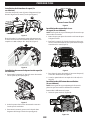
3. Rotate the seat into position and slide a Phillips screwdriver
through one of the seat-securing holes and seat bracket
for alignment.
4. With the previously removed shoulder bolts (a) and flange
lock nuts (b) secure one side of the seat and seat bracket.
While supporting the seat, remove the Phillips screwdriver
and secure the other side of the seat. Be careful not to crimp
or damage the wire harness while installing the seat (Figure
3). Torque to 84-103 in-lbs (9-12 N-m).
a
a
b
b
Figure 3
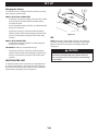
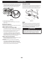
5. Using the harness clip attached to the harness, secure the
excess wire to the fender by snapping the harness clip in
place (Figure 4).
Figure 4

9
SET-UP
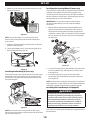
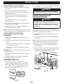
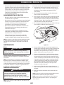
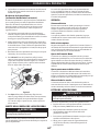
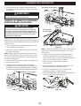
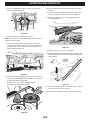
Installing the Hood Collar (if necessary)
There are three (3) alignment posts (a) on the hood collar (b) that
line up with corresponding alignment holes (c) in the hood (d)
(Figure 5).
a
a
a
a
b
c
cc
d
Figure 5
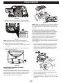
Use these alignment points to properly position the hood collar
(a), then secure it in place with the six hex bolts (b) provided in
the hardware bag. Tighten the hex bolts to 102-124 in-lbs (12-14
N-m) (Figure 6).
a
b b
b
b
Figure 6
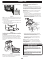
Installing the Snap-On Hood Topper
(if necessary)
1. To install the snap-on hood topper (a), line up the holes
on the hood topper (a) with the tabs (b) in the hood frame
(Figure 7).
a
b
b
b
b
Figure 7
2. Insert the tabs into the hood topper and pull back to lock
into place.
3. Once the hood topper is in place, the two locking tabs near
the rear of the hood need to be pushed upward to lock the
hood topper in place (Figure 8).
Hood Topper Not Shown for Clarity
Figure 8
Installing the Screw-On Hood Topper
(if necessary)
NOTE: Be careful not to damage the headlight harness when
installing the screw-on hood topper.
1. Set the hood topper up against the top of the hood with the
hood open, and align the holes on the hood.
2. Secure the screw-on hood topper (a) from below, hand-
tighten the screws (b) on the rear half of the hood and then
snug them (Figure 9).
3. With the rear screws in place, align the holes in the hood
topper (a) with the holes in the hood (c) and secure in place
with remaining two screws (d) (Figure 9).
a
bb
c
d d
Figure 9
4. Tighten all four screws to 16-24 in-lbs (2-3 N-m).
Installing the Plenum (if necessary)
NOTE: Be careful not to damage the headlight harness when
installing the plenum.
To install the plenum onto the hood:
1. Insert the rear tabs (c) (Figure 10).
a
b
c
Figure 10

10
SET-UP
2. With the rear tabs installed, insert the front tabs (a) on the
plenum (b) (Figure 11).
a
baa
Figure 11
NOTE: The rear tabs fit into a recessed area on the top of
the hood. They slide up from under the hood and into these
recessed areas.
3. Push up on the bottom of the plenum to make sure that the
plenum is securely in place.
4. Secure the headlight harness (a) into the two guides (b) on
the front of the plenum (Figure 12).
a
b b
Figure 12
Installing the Dash Cap (if necessary)
To install the dash cap (a), line up the tabs (b) on the dash cap (a)
with the holes in the upper dash (Figure 13). Slide the tabs (b)
into the holes in the upper dash and push forward on the dash
cap to lock into place.
a
b
Figure 13
NOTE: Be sure to press on the lower part of the dash cap (a)
facing the operator position to ensure the lower tabs on the dash
cap are in place (Figure 13).
Installing the Steering Wheel (if necessary)
The hardware for attaching the steering wheel has been packed
within the steering wheel, beneath the steering wheel cap.
Carefully remove the cover by inserting a small flat screwdriver
into one of the three snap locations, and slowly prying up on the
steering wheel cap to remove the hardware.
IMPORTANT! Do not use impact tools to install or remove
the steering wheel. Doing so can over-torque and damage
the fastener.
1. With the wheels of the tractor pointing straight forward,
align the steering wheel (a) by using the center-line (b) on
the front of the steering wheel (a) pointing straight ahead
and the flat section (c) of the steering wheel (a) facing toward
the seat, place the steering wheel (a) over the steering shaft
(d) (Figure 14).
a
d
e
f
b
c
Figure 14
2. Secure the steering wheel (a) with the hex bolt (e) from under
the steering wheel cap (f) and torque to 18-22 ft-lbs (24-30
N-m) (Figure 14).
3. Place the steering wheel cap (f) over the center of the
steering wheel (a) and push downward until it “clicks” into
place (Figure 14).
NOTE: The hex bolt (e) securing the steering wheel (a) has thread
locker applied to it, so if it is removed, it is recommended that the
hex bolt (e) be replaced or thread lock re-applied (Figure 14).
Installing the Front Bumper (if equipped)
WARNING
Disengage the PTO, engage the brake lock, and stop
the tractor engine before performing any preparation
procedures. Place the tractor on a firm and level surface
before beginning installation or removal procedures.
The exhaust system and surrounding areas are HOT. To
avoid personal injury, allow the tractor to cool before
beginning any installation or removal procedures.
The hardware for attaching the front bumper is shipped installed
into the bumper.

11
SET-UP
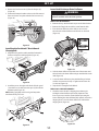
1. Remove the four hex screws (a) from the bumper (b)
(Figure 15).
2. Position the bumper brackets to the inside of the tractor’s
frame and secure it in place with the four hex screws (a)
(Figure 15).
aa
b
Figure 15
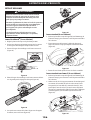
Installing the FastAttach™ Brush Guard
(if equipped)
1. Align the brush guard assembly with the FastAttach™
brackets and push assembly together (Figure 16).
Figure 16
2. Install the pins on the right and left side of brush guard
(1) and then secure with two cotter pins (2) found in the
hardware pack (Figure 17).
NOTE: Pulling up lightly on the brush guard may make
installation of the pins easier.
1
2
Figure 17
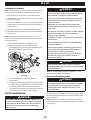
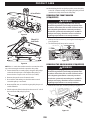
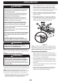
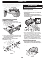
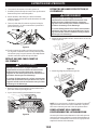
Lower Deck Discharge Chute Deflector
WARNING
Never operate the mower deck without the chute
deflector installed and in the down position.
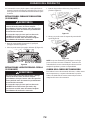
FOR 46 INCH DECK MODELS:
1. Remove the keys attached with a zip tie to the chute bracket.
2. Remove the flange lock nut and hex screw from the deck.
3. Place the chute deflector on the deck, be sure to insert
the tabs on the chute deflector into the holes on the deck
(Figure 18).
3
4
4
5
5
Figure 18
4. Slide the chute deflector toward the rear of the tractor until
the bolt hole in the chute deflector aligns with the hole in the
deck (Figure 18).
5. Secure the chute deflector in place with the flange lock nut
and hex screw removed in Step 2. Tighten to 102-124 in-lbs
(12-14 N-m) (Figure 18).
6. Skip ahead to Setting the Deck Wheels.
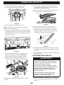
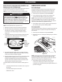
FOR 42/50/54 INCH DECK MODELS:
1. Check the tractor deck for a shipping brace that may be
holding the chute deflector upward for shipment. If the
brace is present, it must be removed before operating the
tractor. Holding the chute deflector fully upward, remove the
shipping brace. Lower the chute deflector and discard the
shipping brace (Figure 19).
Figure 19

12
SET-UP
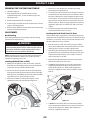
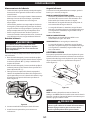
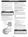
Setting the Deck Wheels
NOTE: The deck wheels are an anti-scalp feature of the deck and
are not designed to support the weight of the cutting deck.
1. Move the tractor to a level surface, preferably pavement.
2. Check the tire pressure, adjust, if necessary. See tire sidewall
for proper tire pressure.
3. Make sure the deck is level side-to-side and properly pitched.
See the Product Care section for deck leveling information
and instructions.
4. Place deck lift lever in the desired mowing height position.
5. Check the wheels for contact or excessive clearance with the
surface below.
NOTE: The deck wheels should have between 1/4-1/2 inch
(6.35-12.7 mm) clearance above the ground. Proceed as follows
to adjust the wheels:
a. Raise the deck lift handle to its highest setting.
b. Remove the front (a) and rear (b) deck wheels by
removing the flange lock nuts (c) and shoulder bolts (d)
that secure them to the deck (Figure 20).
a
bd
c
d
c
Figure 20
c. Place the deck lift lever in the desired mowing
height setting.
d. Reinsert the shoulder bolt (with each deck wheel) into the
index hole that leaves approximately 1/2 inch (12.7 mm)
between the bottom of the wheel and the pavement.
Tighten the flange lock nut and shoulder bolt to between
25-30 ft-lbs (34-41 N-m) using a torque wrench.
BATTERY INFORMATION
WARNING
CALIFORNIA PROPOSITION 65 WARNING: Battery posts,
terminals, and related accessories contain lead and lead
compounds, chemicals known to the State of California
to cause cancer and reproductive harm. Wash hands
after handling.
WARNING
Should battery acid accidentally splatter into the eyes or
onto the skin, rinse the affected area immediately with
clean cold water. Seek prompt medical attention.
If acid spills on clothing, first dilute it with clean water,
then neutralize with a solution of ammonia/water or
baking soda/water.
NEVER connect (or disconnect) battery charger clips
to the battery while the charger is turned on, as it can
cause sparks.
Keep all sources of ignition (cigarettes, matches, lighters)
away from the battery. The gas generated during
charging can be combustible.
As a further precaution, only charge the battery in a well
ventilated area.
Always shield eyes and protect skin and clothing when
working near batteries.
Batteries contain sulfuric acid and may emit explosive
gases. Use extreme caution when handling batteries.
Keep batteries out of the reach of children.
The battery may present a risk of fire or chemical burn
if misused. Do not open, disassemble, overheat, or
incinerate the battery.
CAUTION
When attaching battery cables, always connect the
POSITIVE (Red) wire to the terminal first, followed by the
NEGATIVE (Black) wire.
NOTE: The positive battery terminal is marked Pos. (+). The
negative battery terminal is marked Neg. (–).
Connecting the Battery Cables
WARNING
Always connect the positive lead to the battery before
connecting the negative lead. This will prevent sparking
or possible injury from an electrical short caused by
contacting the tractor body with tools being used to
connect the cables.
For shipping reasons the factory may leave both battery cables
disconnected from the terminals. To connect the battery cables,
proceed as follows:
NOTE: Wiring harness should lay on top of battery hold down
rod, otherwise damage to the wiring harness may result (Figure
22 on page 13).

13
SET-UP
1. Remove the factory installed hex screws (a) and square
nuts (b) located either on the end of the wiring harness or
in the bag with this manual. Retain the hardware for later
instructions (Figure 21).
2. Remove the plastic cover (c), if present, from the positive
battery terminal (d) and attach the red cable (e) to the
positive battery terminal (d) with one of the hex screws (a)
and square nuts (b), from Step 1. Use a Philips screw driver
(Figure 21).
3. Position the red rubber boot over the positive battery
terminal to help protect it from corrosion (Figure 21 inset).
4. Remove the plastic cover (c), if present, from the negative
battery terminal (f) and attach the black cable (g) to the
negative battery terminal (f) with the remaining hex screw
(a) and square nut (b) (Figure 21).
a
b
b
c
e
d
fg
c
a
Figure 21
NOTE: If the battery is put into service after the date shown
on top/side of battery, charge the battery as instructed in the
Charging the Battery section prior to operating the tractor.
Battery Maintenance
• Some batteries are filled with battery acid and then sealed
at the factory. However, even a “maintenance free” battery
requires some maintenance to ensure its proper life cycle.
• Spray the terminals and exposed wire with a battery
terminal sealer, or coat the terminals with a thin coat of
grease or petroleum jelly, to protect against corrosion.
• Always keep the battery cables and terminals clean and free
of corrosion.
• Some models are equipped with a battery containing a
liquid electrolyte. Handle the battery with care and avoid
tipping to prevent leakage.
Battery Storage
• When storing the tractor for extended periods, disconnect
the negative battery cable. It is not necessary to remove
the battery.
• All batteries discharge during storage. Keep the exterior
of the battery clean, especially the top. A dirty battery will
discharge more rapidly.
• The battery must be stored with a full charge. A discharged
battery can freeze sooner than a charged battery. A fully
charged battery will store longer in cold temperatures
than hot.
• Recharge the battery before returning to service. Although
the tractor may start, the engine charging system may not
fully recharge the battery.
Battery Removal
WARNING
Battery posts, terminals, and related accessories contain
lead and lead compounds. Wash hands after handling.
The battery is located beneath the seat frame. To remove
the battery:
1. Remove the hex screw and square nut securing the black
negative battery lead to the negative battery post (marked
NEG (-)). Move the cable away from the negative battery post.
2. Remove the hex screw and square nut securing the red
positive battery lead to the positive battery post (marked
POS (+)).
3. Remove the battery hold down rod by pushing the hooked
end out of the tab on the fender to the right side of the
battery. Then flip the battery hold down rod up to free the
battery (Figure 22).
Figure 22
4. Carefully lift the battery out of the tractor.
5. Install the battery by repeating the above steps in the
reverse order.

14
SET-UP
Charging the Battery
Test and, if necessary, recharge the battery after the tractor has
been stored for a period of time.
MODELS WITH LEAD-ACID BATTERY
• A voltmeter or load tester reading of 12.4 volts (DC) or lower
across the battery terminals indicates that the battery
needs to be charged.
• A lead-acid battery charger should be used. Recommended
charge rate is 4A/14.7V.
• If your battery charger is automatic, charge the battery
until the charger indicates that charging is complete. If the
charger is not automatic, charge for no fewer than eight
(8) hours.
MODELS WITH AGM BATTERY
• An AGM battery charger should be used. Recommended
charge rate is 1.1A/14.8V.
IMPORTANT! Do NOT use an automotive charger.
• If your battery charger is automatic, charge the battery
until the charger indicates that charging is complete. If the
charger is not automatic, charge for no fewer than eight
(8) hours.
ADJUSTING THE SEAT
To adjust the position of the seat, lift the seat adjustment lever
up. Slide the seat forward or rearward to the desired position;
then release the adjustment lever. Make sure seat is locked into
position before operating the tractor (Figure 23).
Figure 23
OIL
NOTE: Your tractor is shipped with oil in the engine. However,
you MUST check the oil level before operating. See the Engine
Operator’s Manual for instructions on checking, adding and
changing oil.
CAUTION
Always check the engine oil level before each use as
instructed in the Engine Operator’s Manual. Add oil as
necessary. Failure to do so may result in serious damage
to your engine.

15
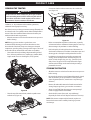
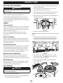
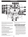
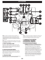
OPERATION
M
Q
O
N
P
C
D
I
G
K
L
A
B
F
D1
D2
EH
D3
J
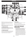
Figure 24
NOTE: This Operator’s Manual covers several models. Tractor
features may vary by model. Not all features in this manual are
applicable to all tractor models and the tractor depicted may
differ from yours.
NOTE: All references in this manual to the left or right side and
front or back of the tractor are from the operating position only.
Exceptions, if any, will be specified.
A. FORWARD DRIVE PEDAL
Depress the forward drive pedal forward to allow the tractor to
travel forward. The further forward the pedal is depressed, the
faster the tractor will travel. The pedal will return to its original/
neutral position when it is not depressed.
B. REVERSE DRIVE PEDAL
Depress the reverse drive pedal downward to allow the tractor to
travel backward. The further downward the pedal is depressed,
the faster the tractor will travel. The pedal will return to its
original/neutral position when it is not depressed.
C. BRAKE PEDAL
Depress the brake pedal while the tractor is in use to stop the
tractor and for setting the parking brake.
NOTE: The brake pedal must be fully depressed to start the
tractor. Refer to Safety Interlock System for more information.
D. THROTTLE/CHOKE CONTROL LEVER,
THROTTLE CONTROL, OR ELECTRONIC
GOVERNOR CONTROL
1. Throttle/Choke Control Lever (if equipped) - Push
the throttle/choke control lever forward to increase
the engine speed. The tractor is designed to operate
with the throttle/choke control lever at full throttle
(FAST) when the tractor is being driven and the mower
deck is engaged. Pull the throttle/choke control lever
rearward to decrease the engine speed. When starting
the engine, push the control lever fully forward into the
CHOKE position. After starting and warming the engine,
move the control lever rearward until you feel it move
past the choke detent. Throttle is not meant to control
unit speed, throttle should remain in high speed while
operating blades.

16
OPERATION
CAUTION
Prior to operating the tractor, refer to both Stopping the
Engine and Starting the Engine in the Operation section
of this manual for detailed instructions regarding the
ignition switch module and operating the tractor in
REVERSE CAUTION MODE .
PBS (Push Button Start)/Service Minder and Hour
Meter (if equipped)
WARNING
Never leave a running tractor unattended. Always
disengage PTO, set parking brake, stop tractor, and
remove the key to prevent unauthorized operation.
NOTE: If the REVERSE CAUTION MODE button is depressed
during starting, the starting sequence is aborted and needs to
be restarted.
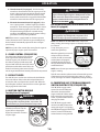
To stop the engine, press or
remove the ignition key.
When the ignition key is inserted
and pressed for less than 0.5
seconds, the LCD service minder
and hour meter (if equipped)
will briefly display the battery
voltage, followed by the tractor’s
accumulated hours.
NOTE: Hours of tractor operation are recorded only when the
engine is running.
The LCD service minder and hour meter will remind the operator
of maintenance intervals for changing the engine oil, air filter
service, low engine oil and low or high battery voltage warnings.
H. POWER TAKEOFF PTOBLADE ENGAGE
SWITCH ELECTRIC PTO IF EQUIPPED
The PTO (blade engage) switch
operates the electric PTO clutch
mounted on the bottom of the
engine crankshaft. Pull the switch
knob outward to engage the PTO
clutch, or push the knob inward to
disengage the clutch.
The PTO (blade engage) switch
must be in the OFF position when
starting the engine. See Engaging
the PTO (Blade Engage) (Electric PTO
tractors) section for information
and instructions on using the PTO.
1 2 3
0.5
sec.
3
sec.
STOP
R
2. Throttle Control (if equipped) - Push the throttle
control lever forward to increase the engine speed. The
tractor is designed to operate with the throttle control
lever at full throttle (FAST) when the tractor is being
driven and the tractor deck is engaged. Pull the throttle
control lever rearward to decrease the engine speed.
3. Electronic Governor Control (if equipped) - When
set in a given position, a uniform engine speed will be
maintained. The electronic governor control has various
inputs for maintaining engine speed. Use CUT setting
for optimal cutting performance in normal cutting
conditions. Use POWER CUT setting for optimal cutting
performance in heavy cutting conditions.
NOTE: If the tractor is equipped with an electronic governor
control, the tractor can be started at any speed setting along
the dial and will automatically adjust to the desired engine
speed setting.
NOTE: It may take a few seconds after starting for the engine to
adjust to the proper engine speed. This is normal.
E. CHOKE CONTROL IF EQUIPPED
The choke control determines the position
of the engine choke. Pull the knob out to
choke the engine; push the knob in to open
the choke. If equipped, choke control will
be paired with a throttle control (D2). When
pulled outward the choke control closes the
choke for cold starting. Once started always
run the engine with the choke control pushed all the way inward.
F. DECK LIFT LEVER
The deck lift lever is used to raise and lower the deck. Pull the
lever to the left out of the index notch and push downward
to lower the deck, or pull upward to raise the deck. When the
desired height is attained, move the lift lever to the right until
fully engaged in the index notch.
G. IGNITION SWITCH MODULE
Turn-Key Start (if equipped)
WARNING
Never leave a running tractor unattended. Always
disengage PTO, set parking brake, stop tractor, and
remove the key to prevent unauthorized operation.
Refer to Starting the Engine for
information on how to start the
engine. Refer to Stopping the
Engine for instructions on how to
stop the engine.

17
OPERATION
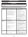
Change Oil
The LCD screen will alternate the letters “CHG”, followed by “OIL”,
followed by “SOON”, followed by the meter’s accumulated time.
“CHG/OIL/SOON/TIME” will alternate on the display for 7 minutes
after the meter reaches 50 hours. This oil service minder interval
will occur every 50 hours. Before the interval expires, change the
engine oil as instructed in the Engine Operator’s Manual.
Low Oil
NOTE: The low oil pressure function only works if the engine is
equipped with an oil pressure switch.
The LCD screen will alternate the letters “LO” followed by “OIL”,
followed by the meter’s accumulated time, which indicates
the engine has low oil pressure. This is common when starting
an engine. The indicator will remain active until the engine
sufficiently builds pressure after starting. If it remains on with
the engine at full speed and after a few minutes of operation,
stop the tractor immediately, check the engine oil level and
add as instructed in the Engine Operator’s Manual. If the oil
level is correct and the indicator persists, contact an authorized
service dealer.
Low Battery
At startup, the battery voltage will briefly display, then changes
to accumulated hours. The letters “LO” followed by the letters
“BATT” will display, followed by the meter’s accumulated time.
“LO/BATT/TIME” is displayed on the LCD when the voltage
drops below 11.5 volts. When this occurs, the battery is in need
of a charge or the engine’s charging system is not generating
sufficient amperage. Charge the battery as instructed in the
Charging the Battery section of this manual or have the charging
system checked by your local service dealer.
Air Filter Service
The LCD screen will display the letters “CLN” followed by
the letters “AIR”, followed by “FILT”, followed by the meter’s
accumulated time. “CLN/AIR/FILT/TIME” will alternate on the
display for 7 minutes after the meter reaches 25 hours. This air
filter service minder time interval will be every 25 hours. On
intervals that are common with oil service, the oil message will
be displayed first followed by the air filter message.
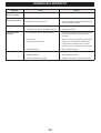
M. FUEL TANK CAP
Turn the fuel cap at least two clicks counter-clockwise and pull
upward to remove. The fuel cap is tethered to the fuel tank to
prevent its loss. Do not attempt to remove the cap from the fuel
tank. Fill tank to 1/2 inch (12.7 mm) below the bottom of the
filler neck, allowing some space in the tank for fuel expansion.
Do not overfill the tank. The fuel tank holds approximately 2.5
(9.46 L) (EFI engines only) or 3 gallons (11.35 L) of gasoline.
Push the cap downward on the fuel tank filler neck and turn at
least two clicks clockwise to tighten. Always re-install the fuel
cap tightly onto the fuel tank after removing.
I. PTO BLADE ENGAGE LEVER
MANUAL PTO
Activating the PTO (blade engage) lever engages power to the
cutting deck or other (separately available) attachments. See
Engaging the PTO (Blade Engage) (Manual PTO tractors) section
for information and instructions on using the PTO.
J. TRANSMISSION BYPASS ROD
When engaged, the rod opens a bypass within
the hydrostatic transmission, which allows the
tractor to be pushed short distances by hand.
Refer to the Set-Up section for instructions on
using the bypass feature.
CAUTION
Never tow your tractor. Towing the tractor with the
rear wheels on the ground may cause severe damage to
the transmissions.
K. PARK BRAKE/CRUISE CONTROL LEVER
The park brake/
cruise control
lever is used
to engage the
parking brake
and the cruise
control. Refer to the Driving the Tractor section of this manual for
detailed instructions regarding the parking brake.
NOTE: The parking brake must be set if the operator leaves the
seat with the engine running or the engine will automatically
shut off.
NOTE: Cruise control CANNOT be engaged at the tractor’s fastest
ground speed.
L. LCD SERVICE MINDER AND HOUR METER
IF EQUIPPED
The LCD service minder and
hour meter (if equipped)
will remind the operator of
maintenance intervals for
changing the engine oil, air
filter service, low engine oil
pressure and low battery
warnings. When the key is rotated out of the STOP position but is
not in the START position, the LCD service minder and hour meter
(if equipped) will briefly display the battery voltage, followed by
the tractor’s accumulated hours.
NOTE: When the ignition key is out of the STOP position the
hourglass symbol is illuminated/blinks to indicate it is recording
the hours of tractor operation, regardless of whether the engine
has been started.

18
OPERATION
WARNING
Never fill the fuel tank when the engine is running. If the
engine is hot from recently running, allow to cool for at
least five minutes before refueling. Highly flammable
gasoline could splash onto the engine and cause a fire.
N. STORAGE TRAY
The storage tray is located to the left of the operator’s seat.
O. CUP HOLDER
The cup holder is located to the left of the operator’s seat.
P. DIFFERENTIAL LOCK PEDAL IF EQUIPPED
Activating the differential lock increases traction by maintaining
equal wheel speed on the rear tires. See Using the Differential
Lock (if equipped) section for more information on using the
differential lock.
Q. SEAT ADJUSTMENT LEVER
The seat adjustment lever allows for adjustment forward or
backward of the operator’s seat. Refer to the Set-Up section for
instructions on adjusting the seat position.
HEADLIGHTS NOT SHOWN
On turn-key tractors the lights are ON whenever the ignition key
is rotated out of the STOP position. The lights turn OFF when the
ignition key is moved to the STOP position.
On PBS tractors the lights are ON whenever the PBS module is
on. Headlights can be activated for 15 seconds without being on
the seat by pressing the ignition key once. To keep the headlights
active you can sit in the seat or start/run the engine.
OPERATION
Before Operating Your Tractor
• Before operation, refer to the Maintenance Schedule chart
located in this manual for regularly scheduled service items.
• This engine is certified to operate only on clean, fresh,
unleaded gasoline. Fill only with clean, fresh, unleaded
gasoline with a pump sticker octane rating of 87 or higher.
• Do not use gasoline left over from the previous season, to
minimize gum deposits in the fuel system.
• Gasohol (up to 10% ethyl alcohol, 90% unleaded gasoline by
volume) is an approved fuel. Other gasoline/alcohol blends
are not approved.
• Methyl Tertiary Butyl Ether (MTBE) and unleaded gasoline
blends (up to a maximum of 15% MTBE by volume)
are approved fuels. Other gasoline/ether blends are
not approved.
Safety Interlock System
WARNING
Do not operate the tractor if the safety interlock system
is malfunctioning. This system was designed for your
safety and protection.
This tractor is equipped with a safety interlock system for
the protection of the operator. If the safety interlock system
should ever malfunction, do not operate the tractor. Contact an
authorized service dealer.
• The safety interlock system prevents the engine from
cranking or starting unless the parking brake is engaged
or the operator is in the seat and the brake pedal is fully
depressed, with the PTO (blade engage) switch or PTO (blade
engage) lever in the disengaged (OFF) position.
• The engine will automatically shut off if the operator leaves
the seat before engaging the parking brake.
• The engine will automatically shut off if the operator leaves
the tractor’s seat with the PTO (blade engage) switch or
PTO (blade engage) lever in the ENGAGED (ON) position,
regardless of whether the parking brake is engaged.
• With the ignition key in the NORMAL MOWING MODE position,
the electric PTO (blade engage) clutch will automatically shut
off if the PTO (blade engage) switch or PTO (Blade engage)
lever is moved into the engaged (ON) position with the drive
pedal in position for reverse travel.
Checking the Safety Interlock Circuits
Periodically check the safety interlock circuits to ensure they are
working properly. If a safety circuit is not working as designed,
contact your authorized service dealer to have the tractor
inspected. Do not operate the tractor if any safety circuit is
not functioning properly. To check the safety circuits, proceed
as follows:
1. With the engine off and sitting in the seat, place the PTO
control (PTO (Blade engage) switch or PTO (Blade engage)
lever) to the ENGAGED (ON) position. Momentarily turn the
ignition switch to the START position; the engine should
not crank.
2. With the tractor running, and the parking brake not engaged;
lift upward from the operator’s seat. The engine should stop.
3. With the parking brake engaged, engage the PTO. Lift
upward from the operator’s seat; the engine should stop.
Starting the Engine
CAUTION
The operator should be sitting in the tractor seat when
starting the engine.
Continue for turn-key ignitions, skip ahead to the PBS Ignition
section for push-button start ignitions.

19
OPERATION
CAUTION
Do not hold the key in the START position for longer than
ten seconds at a time. Doing so may cause damage to
your engine’s electric starter.
6. As the engine warms up, gradually pull the throttle/choke
control lever rearward past the choke detent position. Do not
use the choke position to enrich the fuel mixture, except as
necessary to start the engine.
7. Allow the engine to run for a few minutes at mid-throttle
before putting the engine under load.
NOTE: When operating the tractor be certain that the throttle
lever is always in the FAST position.
8. Observe the LCD service minder and hour meter (if equipped).
If the battery indicator light or oil pressure light comes on,
immediately stop the engine. Have the tractor inspected by
your authorized service dealer.
NOTE: There will be no oil pressure when the engine is not
running and this may be indicated by oil pressure light.
TURNKEY IGNITION WITH ELECTRONIC GOVERNOR
CONTROL
1. Insert the ignition key into the ignition switch.
2. Place the PTO (blade engage) switch or PTO (blade engage)
lever in the OFF position.
3. Engage the tractor parking brake.
4. Set the electronic governor control dial to the desired engine
speed setting.
NOTE: If the tractor is equipped with an electronic governor
control, the tractor can be started at any speed setting along
the dial and will automatically adjust to the desired engine
speed setting.
5. Turn the ignition key clockwise to the START position.
After the engine starts, release the key. It will return to the
NORMAL MOWING MODE position.
NOTE: It may take a few seconds after starting for the engine to
adjust to the proper engine speed. This is normal.
PBS IGNITION
1. Place the PTO (blade engage) switch or PTO (blade engage)
lever in the OFF position and sit in the seat. You must be in the
seat for the PBS ignition to work.
2. Insert the ignition key.
3. Engage tractor parking brake.
4. Move the throttle into the FAST position.
5. Press and hold the ignition key. After the engine starts,
release the key. It will return to an extended position.
NOTE: When operating the tractor be certain that the throttle
control lever is always in the FAST position. Operating with
the throttle at less than full throttle may lead to shortened
battery life.
TURNKEY IGNITION WITH SEPARATE THROTTLE AND
CHOKE CONTROL
1. Insert the ignition key into the ignition switch.
2. Place the PTO (blade engage) switch or PTO (blade engage)
lever in the OFF position.
3. Engage the tractor’s parking brake.
4. Engage the choke control (if equipped).
NOTE: If the engine is warmed up, it may not be necessary to
choke the engine.
5. Move the throttle control lever to midway between the FAST
and SLOW positions.
NOTE: When operating the tractor be certain that the throttle
lever is always in the FAST position.
6. Turn the ignition key clockwise to the START position.
After the engine starts, release the key. It will return to the
NORMAL MOWING MODE position.
CAUTION
Do not hold the key in the START position for longer than
ten seconds at a time. Doing so may cause damage to
your engine’s electric starter.
7. As the engine warms up, disengage the choke control. Do not
use the choke control to enrich the fuel mixture, except as
necessary to start the engine.
8. Allow the engine to run for a few minutes at mid-throttle
before putting the engine under load.
NOTE: When operating the tractor be certain that the throttle
control lever is always in the FAST position.
9. Observe the LCD service minder and hour meter (if equipped)
panel. If the battery indicator light or oil pressure light comes
on, immediately stop the engine. Have the tractor inspected
by your authorized service dealer.
NOTE: There will be no oil pressure when the engine is not
running and this may be indicated by oil pressure light.
TURNKEY IGNITION WITH THROTTLE/CHOKE CONTROL
1. Insert the ignition key into the ignition switch.
2. Place the PTO (blade engage) switch or PTO (blade engage)
lever in the OFF position.
3. Engage the tractor’s parking brake.
4. Push the throttle control lever upward, past the detent, to
engage the choke.
NOTE: If the engine is warmed up, it may not be necessary to
choke the engine.
5. Turn the ignition key clockwise to the START position.
After the engine starts, release the key. It will return to the
NORMAL MOWING MODE position.

20
OPERATION
Cold Weather Starting
When starting the engine at temperatures near or below
freezing, ensure the correct viscosity motor oil is used in the
engine and the battery is fully charged. Start the engine
as follows:
1. Be sure the battery is in good condition. A warm battery has
much more starting capacity than a cold battery.
2. Use fresh winter grade fuel. Winter grade gasoline has higher
volatility to improve starting. Do not use gasoline left over
from summer.
3. Follow the previous instruction for Starting the Engine.
Using Jumper Cables To Start Engine
WARNING
Batteries contain sulfuric acid and produce explosive
gases. Make certain the area is well ventilated, wear
gloves and eye protection, and avoid sparks or flames
near the battery.
If the battery charge is not sufficient to crank the engine,
recharge the battery. If a battery charger is unavailable and
the tractor must be started, the aid of a booster battery will be
necessary. Connect the booster battery as follows:
1. Connect the end of one cable to the disabled tractor battery’s
positive terminal; then connect the other end of that cable to
the booster battery’s positive terminal.
2. Connect one end of the other cable to the booster battery’s
negative terminal; then connect the other end of that cable
to the frame of the disabled tractor, as far from the battery
as possible.
3. Start the disabled tractor following the normal starting
instructions previously provided; then disconnect the jumper
cables in the exact reverse order of their connection.
4. Have the tractor’s electrical system checked and repaired as
soon as possible to eliminate the need for jump starting.
Stopping the Engine
1. If the blades are engaged, place the PTO (blade engage)
switch or PTO (blade engage) lever in the OFF position.
2. Engage the tractor parking brake.
3. Place the throttle control to midway between the FAST and
SLOW positions.
4. Turn the ignition key counter-clockwise to the STOP position,
or on PBS units press or remove the ignition key.
DRIVING THE TRACTOR
WARNING
Keep all movement of the Forward and Reverse drive
pedals and brake pedal slow and smooth. Abrupt
movement of the drive pedals or brake pedal can affect
the stability of the tractor and could cause the tractor to
flip over, which may result in serious injury or death to
the operator.
1. Depress the brake pedal to release the parking brake. Move
the throttle into the FAST position.
2. To travel FORWARD, slowly depress the forward drive pedal
(a) forward until the desired speed is achieved (Figure 25).
3. To travel in REVERSE, check that the area behind is clear then
slowly depress the reverse drive pedal (b) until the desired
speed is achieved (Figure 25).
b
a
Figure 25
WARNING
• Sharp turns can affect control of the tractor. ALWAYS
slow the tractor before making sharp turns.
• Do not leave the seat of the tractor without first
placing the PTO (blade engage) switch or lever in the
DISENGAGED (OFF) position and engaging the parking
brake. If leaving the tractor unattended, also turn the
engine off and remove the ignition key.
ENGAGING THE PARKING BRAKE
NOTE: The parking brake must be set if the operator leaves the
seat with the engine running or the engine will automatically
shut off.
To set the parking brake:
1. Depress the brake pedal completely down with your left foot
and hold it in that position.
2. Depress the park brake/cruise control lever and hold it in
that position.
3. Remove your foot from the brake pedal.
Page is loading ...
Page is loading ...
Page is loading ...
Page is loading ...
Page is loading ...
Page is loading ...
Page is loading ...
Page is loading ...
Page is loading ...
Page is loading ...
Page is loading ...
Page is loading ...
Page is loading ...
Page is loading ...
Page is loading ...
Page is loading ...
Page is loading ...
Page is loading ...
Page is loading ...
Page is loading ...
Page is loading ...
Page is loading ...
Page is loading ...
Page is loading ...
Page is loading ...
Page is loading ...
Page is loading ...
Page is loading ...
Page is loading ...
Page is loading ...
Page is loading ...
Page is loading ...
Page is loading ...
Page is loading ...
Page is loading ...
Page is loading ...
Page is loading ...
Page is loading ...
Page is loading ...
Page is loading ...
Page is loading ...
Page is loading ...
Page is loading ...
Page is loading ...
Page is loading ...
Page is loading ...
Page is loading ...
Page is loading ...
Page is loading ...
Page is loading ...
Page is loading ...
Page is loading ...
Page is loading ...
Page is loading ...
Page is loading ...
Page is loading ...
Page is loading ...
Page is loading ...
Page is loading ...
Page is loading ...
Page is loading ...
Page is loading ...
Page is loading ...
Page is loading ...
Page is loading ...
Page is loading ...
Page is loading ...
Page is loading ...
Page is loading ...
Page is loading ...
Page is loading ...
Page is loading ...
Page is loading ...
Page is loading ...
Page is loading ...
Page is loading ...
Page is loading ...
Page is loading ...
Page is loading ...
Page is loading ...
Page is loading ...
Page is loading ...
Page is loading ...
Page is loading ...
Page is loading ...
Page is loading ...
Page is loading ...
Page is loading ...
Page is loading ...
Page is loading ...
Page is loading ...
Page is loading ...
-
 1
1
-
 2
2
-
 3
3
-
 4
4
-
 5
5
-
 6
6
-
 7
7
-
 8
8
-
 9
9
-
 10
10
-
 11
11
-
 12
12
-
 13
13
-
 14
14
-
 15
15
-
 16
16
-
 17
17
-
 18
18
-
 19
19
-
 20
20
-
 21
21
-
 22
22
-
 23
23
-
 24
24
-
 25
25
-
 26
26
-
 27
27
-
 28
28
-
 29
29
-
 30
30
-
 31
31
-
 32
32
-
 33
33
-
 34
34
-
 35
35
-
 36
36
-
 37
37
-
 38
38
-
 39
39
-
 40
40
-
 41
41
-
 42
42
-
 43
43
-
 44
44
-
 45
45
-
 46
46
-
 47
47
-
 48
48
-
 49
49
-
 50
50
-
 51
51
-
 52
52
-
 53
53
-
 54
54
-
 55
55
-
 56
56
-
 57
57
-
 58
58
-
 59
59
-
 60
60
-
 61
61
-
 62
62
-
 63
63
-
 64
64
-
 65
65
-
 66
66
-
 67
67
-
 68
68
-
 69
69
-
 70
70
-
 71
71
-
 72
72
-
 73
73
-
 74
74
-
 75
75
-
 76
76
-
 77
77
-
 78
78
-
 79
79
-
 80
80
-
 81
81
-
 82
82
-
 83
83
-
 84
84
-
 85
85
-
 86
86
-
 87
87
-
 88
88
-
 89
89
-
 90
90
-
 91
91
-
 92
92
-
 93
93
-
 94
94
-
 95
95
-
 96
96
-
 97
97
-
 98
98
-
 99
99
-
 100
100
-
 101
101
-
 102
102
-
 103
103
-
 104
104
-
 105
105
-
 106
106
-
 107
107
-
 108
108
-
 109
109
-
 110
110
-
 111
111
-
 112
112


Troy-Bilt 13APA1BNA66 User manual
- Category
- Lawnmowers
- Type
- User manual
- This manual is also suitable for
Ask a question and I''ll find the answer in the document
Finding information in a document is now easier with AI
in other languages
- français: Troy-Bilt 13APA1BNA66 Manuel utilisateur
- español: Troy-Bilt 13APA1BNA66 Manual de usuario