
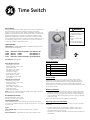
APPLICATION
The GE Time Switches (56922, 15087, 15207) are universal, electromechanical
time switches which can be field configured for various power supply
voltages. The voltage options include 120VAC, 208/240VAC and 277VAC – all
within the same unit! Selection of the desired supply voltage is easily achieved
by positioning dipswitches on the printed circuit board assembly (consult
Dipswitches Configuration on back). The mechanism is mounted in a NEMA
indoor or outdoor enclosure and is intended for the control of lighting, heating,
air conditioning, pumps, motors, or general electrical circuits in residential,
commercial, industrial and agricultural facilities.
SPECIFICATIONS
Input Voltage: 120 VAC, 208/240 VAC, or 277 VAC in all units based
upon dipswitch configuration.
15087 NEMA 3R Indoor & Outdoor BM-A301US5-O2
15207 NEMA 1 Indoor BM-A301US5-I2
56922 NEMA 1 Indoor BM-A301US5-I2
15132 NEMA 3R Indoor & Outdoor EM-A301US9-O2
Switch Rating: DPDT Models
Normally Open Contacts
40A Resistive, 120-277Vac.
30A General Purpose, 120-277Vac.
20A Resistive, 30Vdc
1 HP, 120Vac ; 2HP, 240Vac ;
20A Ballast, 120-277Vac.
15A Tungsten, 120Vac
5.4A Tungsten, 208-277Vac.
800VA, Pilot Duty, 120Vac.
720VA, Pilot Duty, 240-277Vac.
TV-5, 120Vac
Normally Closed Contacts
30A Resistive, 120-277Vac
15A General Purpose, 120-277Vac
15A Resistive, 30Vdc
20A Ballast, 120-277Vac
1/4HP, 120Vac; 1/2HP, 208-240Vac.
290VA, Pilot, 120Vac.
360VA, Pilot, 208-240Vac.
NOTE: If loads are connected to both NC and NO contacts, both contacts are
decorated to 67% of the above values.
ENVIRONMENTAL RATINGS
Ambient Temperature: –40F to 130F
Humidity: 0-95% RH, Non-condensing
WIRING CONNECTIONS
Screw clamp terminals for up to 2 AWG #8 wires per position. For supply
connections, use 8AWG or larger wires suitable for at least 105° C. Use copper
conductors only.
Lights
Power LED (Orange) – Light illuminates when power is applied to
the timer
Status LED (Green) – Light illuminates when power is applied to load.
Included Hardware
INSTALLATION
CAUTION: Before wiring or servicing, power to this time switch and the
equipment it controls must be turned off. Turning off the time switch only
will not prevent a shock hazard. Replace cover plate within housing before
supplying power to time switch. If you are not comfortable installing this
device please contact a licensed electrician. Before installing this product read
all instructions carefully.
Removing Knockout
1. Select knockouts to be used. Remove the inner 1/2” knockout by inserting
a flathead screwdriver on the inner most ring and carefully punching the
knockout loose. Remove slug. If the 3/4” knockout is required, remove the
outer ring with pliers after removing the 1/2” knockout. Smooth edges with
a knife if necessary.
Please refer to Quick Start Guide for Examples and More Details.
Mounting of the Time Switch Box
NOTE - Before mounting be sure to remove knockouts for the wires, (see Quick
Start Guide)
1. In order to mount the box you will need the 3 supplied anchors and 3
supplied screws from the hardware list above. (Anchors included are
designed for mounting on sheetrock.)
2. Using the box as a template, mark with a pencil where the three pilot holes
will be drilled.
Time Switch
WARNING
Risk of electric shock
•
Shut off power at fuse box or circuit
breaker box before installation
Risk of fire
•
Do not use to control receptacle
outlets
•
Do not exceed electrical ratings
•
Use copper wire only with this device
QTY Hardware
3 M4 Anchors 1” Long
3 M4 Screws 1” Long
2 8 AWG Jumpers for 240V AC
2 10 AWG Jumpers for 120V AC
1 Wire Nut (For Ground Wires)

3. Using the appropriate drill bit size, drill the pilot holes (Note that if drilling
into wood or metal a specialized drill bit may be needed.)
See Drill Diagram.
4. For sheetrock; use a hammer to gently tap the anchors into the pilot holes.
5. Place the box up to the pilot holes or anchors and insert the screws
accordingly.
Wiring the Device to the Timer
NOTE - For outdoor installation (model GE15087), rain tight or wet location
conduit hubs that comply with requirements of UL 514B (standard for fittings
for conduit and outlet boxes) must be used.
1. Remove 2 screws retaining the interior cover panel and remove the panel.
2. Refer to Figure 1 and wiring diagrams to determine appropriate placement
of wires. It is the responsibility of the installer to ensure that all applicable
National and Local code requirements are met. If you are unsure of these
requirements, contact a licensed electrician immediately.
Please refer to Quick Start Guide for Examples and More Details.
3. GROUNDING: This enclosure is of plastic construction and does not require
a ground connection. This enclosure does not provide grounding between
conduits. When using non-metallic conduit or cable, connect the ground
wires of all cables together with the provided wire nut. When metallic
conduit is used; as the grounding connection, use grounding type bushing
and a jumper wire between each conduit.
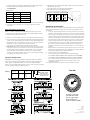
Dipswitch Configuration
WARNING: Failure to properly configure the dipswitch will result in damage
to the unit and void any warranty! Before installing and wiring the GE Time
Switch, proper configuration must be selected. Unit is shipped with DIP
Switches set for 277VAC Input Voltage. Also, do not check circuits by “sparking”
wires to terminals. Damage to timer may result.
4. Determine the input voltage which will be applied to the timer. (120V AC,
208-240V AC, or 277V AC)
5. Set the DIP Switch according to the diagram below:
6. Reinstall interior cover panel. Opposite of step 1.
OPERATING INSTRUCTIONS:
When the Time Switch is installed and power applied, the timer’s dial will turn
clockwise maintaining time. The pointer on the face of the dial points to the
current time
1. Locate the segments around on the outer edge of the timer’s dial. These
segments, each representing 30 minutes, can be pushed down and away
from the edge of the dial (try using the tip of a pen or pencil). Conversely,
segments that have been pushed down can be easily pushed back up by
hand. Be sure all segments are pushed up before programming. Select a
time period (or periods) you want the device turned on, then push down
ALL the segments that fall on or within that time period. For example,
to have the timer turn a device on at 10PM and off at 2AM, push down
the segments representing 10PM and 2AM, and ALL the segments in
between. You may need to turn the dial clockwise to access the desired
segments.
2. Rotate the timer’s dial clockwise until the pointer on the face of the dial
points to the current time of day. Note: Nighttime hours (from 6:30 PM to
6:30 AM) are highlighted with a grey background.
3. Set master switch to the TIMER position.
4. To override timer program and control output load manually:
• set master switch to OFF (center position) to turn load OFF
• set master switch to ON (bottom position) to turn load ON
5. This is a Timer Control and should not be used for power disconnect.
Turn power off at main panel before servicing this switch or the
equipment it controls.
In case of power failure, reset the time of day as explained in step 2.
PRESSURE PLATE
TERMINAL SCREW
MAKE SURE WIRE
INSULATION CLEARS
PRESSURE PLATE
14
12
10
8
15
20
30
40
60
60
60
105
MINIMUM COPPER
WIRE SIZE (AWG)
MAX. LOAD (AMP) MIN. INSULATION
TEMP(°C)
Shows timer set to turn device
ON at 10 PM and OFF at 2 AM.
Notice ALL segments between
10 PM and 2 AM have been
pushed out. Current time is 9:00 PM.
Timer Dial
Soft Wood 5/64”
Material Drill Bit Size
Drill Diagram
Hard Wood 3/32”
Metal 5/64”
Sheetrock 3/16”
No
Anchors Needed?
No
No
Yes
15087
15207
56922
Manual Version 2
11-24-2009
www.jascoproducts.com
4
3
2
1
ON
ON
ON
ON
120VAC
4
3
2
1
OFF
OFF
OFF
OFF
277VAC (Default)
4
3
2
1
OFF
ON
ON
OFF
208~240VAC
Figure 1
-
 1
1
-
 2
2


Ask a question and I''ll find the answer in the document
Finding information in a document is now easier with AI
Related papers
Other documents
-
Jasco 15102 User manual
-
Square D D222NRBCP Specification
-
-
Tork RZ307 User guide
-
Intermatic FM2D50 Series Installation guide
-
Suraielec UBTD01A User guide
-
-
-
-