Gigabyte GA-H81M-S (rev. 1.0) User manual
- Category
- Motherboards
- Type
- User manual

GA-H81M-S
User's Manual
Rev. 1001

Copyright
© 2014 GIGA-BYTE TECHNOLOGY CO., LTD. All rights reserved.
The trademarks mentioned in this manual are legally registered to their respective owners.
Disclaimer
Information in this manual is protected by copyright laws and is the property of GIGABYTE.
Changes to the specications and features in this manual may be made by GIGABYTE without prior notice.
No part of this manual may be reproduced, copied, translated, transmitted, or published in any form or by
any means without GIGABYTE's prior written permission.
In order to assist in the use of this product, carefully read the User's Manual.
For product-related information, check on our website at: http://www.gigabyte.com
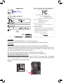
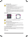
Identifying Your Motherboard Revision
The revision number on your motherboard looks like this: "REV: X.X." For example, "REV: 1.0" means the
revision of the motherboard is 1.0. Check your motherboard revision before updating motherboard BIOS,
drivers, or when looking for technical information.
Example:
Motherboard
GA-H81M-S
May 30, 2014
May 30, 2014
Motherboard
GA-H81M-S

- 3 -
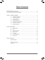
Table of Contents
GA-H81M-S Motherboard Layout .................................................................................... 4
GA-H81M-S Motherboard Block Diagram .......................................................................5
Chapter 1 Hardware Installation .....................................................................................6
1-1 Installation Precautions .................................................................................... 6
1-2 Product Specications ...................................................................................... 7
1-3 Installing the CPU ............................................................................................ 9
1-4 Installing the Memory ....................................................................................... 9
1-5 Installing an Expansion Card ......................................................................... 10
1-6 Back Panel Connectors .................................................................................. 10
1-7 Internal Connectors ........................................................................................ 11
Chapter 2 BIOS Setup ..................................................................................................16
2-1 Startup Screen ............................................................................................... 16
2-2 M.I.T. .............................................................................................................. 17
2-3 System Information ........................................................................................ 21
2-4 BIOS Features ............................................................................................... 22
2-5 Peripherals ..................................................................................................... 25
2-6 Power Management ....................................................................................... 27
2-7 Save & Exit ..................................................................................................... 29
Chapter 3 Appendix ......................................................................................................30
Drivers Installation ..................................................................................................... 30
Regulatory Statements .............................................................................................. 31
Contact Us ................................................................................................................ 33

- 4 -
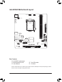
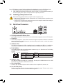
GA-H81M-S Motherboard Layout
The box contents above are for reference only and the actual items shall depend on the product package you obtain.
The box contents are subject to change without notice.
Box Contents
5 GA-H81M-S motherboard
5 Motherboard driver disk 5 Two SATA cables
5 User's Manual 5 I/O Shield
KB_MS
CPU_FAN
LGA1150
ATX
GA-H81M-S
F_AUDIO
AUDIO
DDR3_1
BAT
F_PANEL
ATX_12V
Intel
®
H81
R_USB30
CODEC
CLR_CMOS
M_BIOS
VGA
USB_LAN
PCIEX16
F_USB1
F_USB2
Realtek
®
GbE LAN
iTE
®
Super I/O
DDR3_2
CI
SATA3
1 0
PCIEX1_1
SYS_FAN
SATA2
3 2
SPEAKER

- 5 -
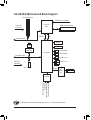
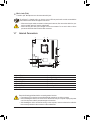
GA-H81M-S Motherboard Block Diagram
For detailed product information/limitation(s), refer to "1-2 Product Specications."
PS/2 KB/Mouse
DMI 2.0
FDI
CPU CLK+/- (100 MHz)
BIOS
DDR3 1600/1333 MHz
Dual Channel Memory
LPC Bus
PCIe CLK
(100 MHz)
PCIe CLK
(100 MHz)
PCI Express Bus
1 PCI Express x16
x1
LAN
RJ45
Realtek
®
GbE LAN
x1
PCI Express Bus
x16
D-Sub
2 SATA 6Gb/s
6 USB 2.0/1.1
2 USB 3.0/2.0
2 SATA 3Gb/s
1 PCI Express x1
Line Out (Front Speaker Out)
MIC (Center/Subwoofer
Speaker Out)
Line In (Rear Speaker Out)
CODEC
iTE
®
Super
I/O
Intel
®
H81
LGA1150
CPU

- 6 -
Chapter 1 Hardware Installation
1-1 Installation Precautions
The motherboard contains numerous delicate electronic circuits and components which can become
damaged as a result of electrostatic discharge (ESD). Prior to installation, carefully read the user's
manual and follow these procedures:
• Prior to installation, make sure the chassis is suitable for the motherboard.
• Prior to installation, do not remove or break motherboard S/N (Serial Number) sticker or
warranty sticker provided by your dealer. These stickers are required for warranty validation.
• Always remove the AC power by unplugging the power cord from the power outlet before
installing or removing the motherboard or other hardware components.
• When connecting hardware components to the internal connectors on the motherboard, make
sure they are connected tightly and securely.
• When handling the motherboard, avoid touching any metal leads or connectors.
• It is best to wear an electrostatic discharge (ESD) wrist strap when handling electronic
components such as a motherboard, CPU or memory. If you do not have an ESD wrist strap,
keep your hands dry and rst touch a metal object to eliminate static electricity.
• Prior to installing the motherboard, please have it on top of an antistatic pad or within an
electrostatic shielding container.
• Before unplugging the power supply cable from the motherboard, make sure the power supply
has been turned off.
• Before turning on the power, make sure the power supply voltage has been set according to
the local voltage standard.
• Before using the product, please verify that all cables and power connectors of your hardware
components are connected.
• To prevent damage to the motherboard, do not allow screws to come in contact with the
motherboard circuit or its components.
• Make sure there are no leftover screws or metal components placed on the motherboard or
within the computer casing.
• Do not place the computer system on an uneven surface.
• Do not place the computer system in a high-temperature environment.
• Turning on the computer power during the installation process can lead to damage to system
components as well as physical harm to the user.
• If you are uncertain about any installation steps or have a problem related to the use of the
product, please consult a certied computer technician.

- 7 -
1-2 ProductSpecications
CPU Support for Intel
®
Core
™
i7 processors/Intel
®
Core
™
i5 processors/
Intel
®
Core
™
i3 processors/Intel
®
Pentium
®
processors/Intel
®
Celeron
®
processors
in the LGA1150 package
(Go to GIGABYTE's website for the latest CPU support list.)
L3 cache varies with CPU
Chipset Intel
®
H81 Express Chipset
Memory 2 x DDR3 DIMM sockets supporting up to 16 GB of system memory
* Due to a Windows 32-bit operating system limitation, when more than 4 GB of physical
memory is installed, the actual memory size displayed will be less than the size of
the physical memory installed.
Dual channel memory architecture
Support for DDR3 1600/1333 MHz memory modules
Support for non-ECC memory modules
Support for Extreme Memory Prole (XMP) memory modules
(Go to GIGABYTE's website for the latest supported memory speeds and memory
modules.)
Onboard
Graphics
Integrated Graphics Processor:
- 1 x D-Sub port, supporting a maximum resolution of 1920x1200
- Maximum shared memory of 1 GB
Audio Realtek
®
ALC887 codec
High Denition Audio
2/4/5.1/7.1-channel
* To congure 7.1-channel audio, you have to use an HD front panel audio module
and enable the multi-channel audio feature through the audio driver.
LAN Realtek
®
GbE LAN chip (10/100/1000 Mbit)
Expansion Slots 1 x PCI Express x16 slot, running at x16
1 x PCI Express x1 slot
(The PCI Express slots conform to PCI Express 2.0 standard.)
Storage Interface Chipset:
- 2 x SATA 6Gb/s connectors (SATA3 0~SATA3 1)
- 2 x SATA 3Gb/s connectors (SATA2 2~SATA2 3)
USB Chipset:
- 2 x USB 3.0/2.0 ports on the back panel
- 6 x USB 2.0/1.1 ports (2 ports on the back panel, 4 ports available through
the internal USB headers)
Internal
Connectors
1 x 24-pin ATX main power connector
1 x 4-pin ATX 12V power connector
2 x SATA 6Gb/s connectors
2 x SATA 3Gb/s connectors
1 x CPU fan header
1 x system fan header
1 x front panel header
1 x front panel audio header
1 x speaker header
2 x USB 2.0/1.1 headers

- 8 -
Internal
Connectors
1 x chassis intrusion header
1 x Clear CMOS jumper
Back Panel
Connectors
1 x PS/2 keyboard port
1 x PS/2 mouse port
1 x D-Sub port
2 x USB 3.0/2.0 ports
2 x USB 2.0/1.1 ports
1 x RJ-45 port
3 x audio jacks (Line In, Line Out, Mic In)
I/O Controller iTE
®
I/O Controller Chip
Hardware
Monitor
System voltage detection
CPU/System temperature detection
CPU/System fan speed detection
CPU/System overheating warning
CPU/System fan fail warning
CPU/System fan speed control
* Whether the fan speed control function is supported will depend on the cooler you
install.
BIOS 1 x 32 Mbit ash
Use of licensed AMI UEFI BIOS
PnP 1.0a, DMI 2.7, WfM 2.0, SM BIOS 2.7, ACPI 5.0
Unique Features Support for Q-Flash
Support for Xpress Install
Support for APP Center
* Available applications in APP Center may differ by motherboard model.
Supported functions of each application may also differ depending on motherboard
specications.
- @BIOS
- EasyTune
- EZ Setup
- USB Blocker
Support for ON/OFF Charge
Bundled
Software
Norton
®
Internet Security (OEM version)
Operating
System
Support for Windows 8.1/8/7
Form Factor
Micro ATX Form Factor; 19.0cm x 17.0cm
* GIGABYTE reserves the right to make any changes to the product specications and product-related information without
prior notice.
* Please visit the Support & Downloads\Utility page on GIGABYTE's website to check the supported operating system(s)
for the software listed in the "Unique Features" and "Bundled Software" columns.

- 9 -
1-3 Installing the CPU
Read the following guidelines before you begin to install the CPU:
• Make sure that the motherboard supports the CPU.
(Go to GIGABYTE's website for the latest CPU support list.)
• Always turn off the computer and unplug the power cord from the power outlet before installing the
CPU to prevent hardware damage.
• Locate the pin one of the CPU. The CPU cannot be inserted if oriented incorrectly. (Or you may
locate the notches on both sides of the CPU and alignment keys on the CPU socket.)
• Apply an even and thin layer of thermal grease on the surface of the CPU.
• Do not turn on the computer if the CPU cooler is not installed, otherwise overheating and damage
of the CPU may occur.
• Set the CPU host frequency in accordance with the CPU specications. It is not recommended
that the system bus frequency be set beyond hardware specications since it does not meet the
standard requirements for the peripherals. If you wish to set the frequency beyond the standard
specications, please do so according to your hardware specications including the CPU, graphics
card, memory, hard drive, etc.
Installing the CPU
Locate the alignment keys on the motherboard CPU socket and the notches on the CPU.
Notch
Alignment Key
Alignment Key
Notch
LGA1150 CPU
LGA1150 CPU Socket
Pin One Corner of the CPU Socket
Triangle Pin One Marking on the CPU
1-4 Installing the Memory
Read the following guidelines before you begin to install the memory:
• Make sure that the motherboard supports the memory. It is recommended that memory of the
same capacity, brand, speed, and chips be used.
(Go to GIGABYTE's website for the latest supported memory speeds and memory modules.)
• Always turn off the computer and unplug the power cord from the power outlet before installing the
memory to prevent hardware damage.
• Memory modules have a foolproof design. A memory module can be installed in only one direction.
If you are unable to insert the memory, switch the direction.
Do not remove the CPU socket cover before inserting the CPU. It may pop off from the load plate
automatically during the process of re-engaging the lever after you insert the CPU.
DualChannelMemoryConguration
This motherboard provides two DDR3 memory sockets and supports Dual Channel Technology. After the memory
is installed, the BIOS will automatically detect the specications and capacity of the memory. Enabling Dual
Channel memory mode will double the original memory bandwidth.
The two DDR3 memory sockets are divided into two channels and each channel has one memory socket as
following:
Channel A: DDR3_1
Channel B: DDR3_2

- 10 -
1-5 Installing an Expansion Card
Read the following guidelines before you begin to install an expansion card:
• Make sure the motherboard supports the expansion card. Carefully read the manual that came
with your expansion card.
• Always turn off the computer and unplug the power cord from the power outlet before installing an
expansion card to prevent hardware damage.
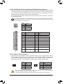
1-6 Back Panel Connectors
PS/2 Keyboard and PS/2 Mouse Ports
Use the upper port (green) to connect a PS/2 mouse and the lower port (purple) to connect a PS/2 keyboard.
D-Sub Port
The D-Sub port supports a 15-pin D-Sub connector and supports a maximum resolution of 1920x1200
(the actual resolutions supported depend on the monitor being used).Connect a monitor that supports
D-Sub connection to this port.
USB 3.0/2.0 Port
The USB 3.0 port supports the USB 3.0 specication and is compatible to the USB 2.0/1.1 specication.
Use this port for USB devices such as a USB keyboard/mouse, USB printer, USB ash drive and etc.
RJ-45 LAN Port
The Gigabit Ethernet LAN port provides Internet connection at up to 1 Gbps data rate. The following
describes the states of the LAN port LEDs.
Due to CPU limitations, read the following guidelines before installing the memory in Dual Channel mode.
1. Dual Channel mode cannot be enabled if only one DDR3 memory module is installed.
2. When enabling Dual Channel mode with two memory modules, it is recommended that memory of
the same capacity, brand, speed, and chips be used for optimum performance.
Activity LED
Connection/
Speed LED
LAN Port
Activity LED:Connection/Speed LED:
State Description
Orange 1 Gbps data rate
Green 100 Mbps data rate
Off 10 Mbps data rate
State Description
Blinking Data transmission or receiving is occurring
Off No data transmission or receiving is occurring
USB 2.0/1.1 Port
The USB port supports the USB 2.0/1.1 specication. Use this port for USB devices such as a USB
keyboard/mouse, USB printer, USB ash drive and etc.
Line In Jack (Blue)
The line in jack. Use this audio jack for line in devices such as an optical drive, walkman, etc.
Line Out Jack (Green)
The line out jack. Use this audio jack for a headphone or 2-channel speaker. This jack can be used to
connect front speakers in a 4/5.1/7.1-channel audio conguration.

- 11 -
To congure 7.1-channel audio, you have to use an HD front panel audio module and enable the
multi-channel audio feature through the audio driver.
• When removing the cable connected to a back panel connector, rst remove the cable from your
device and then remove it from the motherboard.
• When removing the cable, pull it straight out from the connector. Do not rock it side to side to
prevent an electrical short inside the cable connector.
Mic In Jack (Pink)
The Mic in jack. Microphones must be connected to this jack.
1-7 Internal Connectors
1) ATX_12V
2) ATX
3) CPU_FAN
4) SYS_FAN
5) SATA3 0/1
6) SATA2 2/3
7) F_PANEL
8) F_AUDIO
9) F_USB1/F_USB2
10) SPEAKER
11) CI
12) BAT
13) CLR_CMOS
1
2
10
12
13
7
8
9
5
11
6
34
Read the following guidelines before connecting external devices:
• First make sure your devices are compliant with the connectors you wish to connect.
• Before installing the devices, be sure to turn off the devices and your computer. Unplug the power
cord from the power outlet to prevent damage to the devices.
• After installing the device and before turning on the computer, make sure the device cable has
been securely attached to the connector on the motherboard.

- 12 -
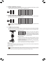
1/2) ATX_12V/ATX (2x2 12V Power Connector and 2x12 Main Power Connector)
With the use of the power connector, the power supply can supply enough stable power to all the components
on the motherboard. Before connecting the power connector, rst make sure the power supply is turned
off and all devices are properly installed. The power connector possesses a foolproof design. Connect the
power supply cable to the power connector in the correct orientation.
The 12V power connector mainly supplies power to the CPU. If the 12V power connector is not connected,
the computer will not start.
3/4) CPU_FAN/SYS_FAN (Fan Headers)
All fan headers on this motherboard are 4-pin. Most fan headers possess a foolproof insertion design.
When connecting a fan cable, be sure to connect it in the correct orientation (the black connector wire is
the ground wire). The speed control function requires the use of a fan with fan speed control design. For
optimum heat dissipation, it is recommended that a system fan be installed inside the chassis.
To meet expansion requirements, it is recommended that a power supply that can withstand high power consumption
be used (500W or greater). If a power supply is used that does not provide the required power, the result can
lead to an unstable or unbootable system.
DEBUG
PORT
G.QBOFM
131
2412
ATX
ATX:
Pin No. Denition Pin No. Denition
1 3.3V 13 3.3V
2 3.3V 14 -12V
3 GND 15 GND
4 +5V 16 PS_ON (soft On/Off)
5 GND 17 GND
6 +5V 18 GND
7 GND 19 GND
8 Power Good 20 -5V
9 5VSB (stand by +5V) 21 +5V
10 +12V 22 +5V
11 +12V (Only for 2x12-pin
ATX)
23 +5V (Only for 2x12-pin ATX)
12 3.3V (Only for 2x12-pin
ATX)
24 GND (Only for 2x12-pin ATX)
CPU_FAN:
Pin No. Denition
1 GND
2 +12V
3 Sense
4 Speed Control
• Be sure to connect fan cables to the fan headers to prevent your CPU and system from overheating. Overheating
may result in damage to the CPU or the system may hang.
• These fan headers are not conguration jumper blocks. Do not place a jumper cap on the headers.
SYS_FAN:
Pin No. Denition
1 GND
2 +12V /Speed Control
3 Sense
4 VCC
ATX_12V
2 1
4 3
ATX_12V:
Pin No. Denition
1 GND
2 GND
3 +12V
4 +12V
SYS_FAN
DEBUG
PORT
G.QBOFM
1
CPU_FAN
DEBUG
PORT
G.QBOFM
1

- 13 -
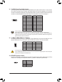
5) SATA3 0/1 (SATA 6Gb/s Connectors)
The SATA connectors conform to SATA 6Gb/s standard and are compatible with SATA 3Gb/s and SATA
1.5Gb/s standard. Each SATA connector supports a single SATA device.
Pin No. Denition Pin No. Denition
1 GND 5 RXN
2 TXP 6 RXP
3 TXN 7 GND
4 GND
7) F_PANEL (Front Panel Header)
Connect the power switch, reset switch, speaker, and system status indicator on the chassis to this header
according to the pin assignments below. Note the positive and negative pins before connecting the cables.
The front panel design may differ by chassis. A front panel module mainly consists of power switch, reset switch,
power LED, hard drive activity LED, speaker and etc. When connecting your chassis front panel module to this
header, make sure the wire assignments and the pin assignments are matched correctly.
SATA3
1 0
7
DEBUG
PORT
G.QBOFM
DEBUG
PORT
G.QBOFM
1
7
1
6) SATA2 2/3 (SATA 3Gb/s Connectors)
The SATA connectors conform to SATA 3Gb/s standard and are compatible with SATA 1.5Gb/s standard.
Each SATA connector supports a single SATA device.
Pin No. Denition Pin No. Denition
1 GND 5 RXN
2 TXP 6 RXP
3 TXN 7 GND
4 GND
SATA2
3 2
7
DEBUG
PORT
G.QBOFM
DEBUG
PORT
G.QBOFM
1
7
1
To enable hot-plugging for the SATA ports, refer to Chapter 2, "BIOS Setup," "Peripherals\SATA
Conguration," for more information.
1
2
PLED-
PW-
PLED+
PW+
Power LED
HD-
RES+
HD+
RES-
Hard Drive
Activity LED
Reset
Switch
Power Switch
9
10
NC
• PW (Power Switch):
Connects to the power switch on the chassis front panel. You may
congure the way to turn off your system using the power switch (refer
to Chapter 2, "BIOS Setup," "Power Management," for more information).
• HD (Hard Drive Activity LED):
Connects to the hard drive activity LED on the chassis front panel. The
LED is on when the hard drive is reading or writing data.
• PLED (Power LED):
System Status LED
S0 On
S3/S4/S5 Off
Connects to the power status indicator
on the chassis front panel. The LED is on
when the system is operating. The LED is
off when the system is in S3/S4 sleep state
or powered off (S5).
• RES (Reset Switch):
Connects to the reset switch on the chassis front panel. Press the reset switch to restart the computer if the
computer freezes and fails to perform a normal restart.
• NC: No connection.

- 14 -
8) F_AUDIO (Front Panel Audio Header)
The front panel audio header supports Intel
®
High Denition audio (HD) and AC'97 audio. You may connect
your chassis front panel audio module to this header. Make sure the wire assignments of the module
connector match the pin assignments of the motherboard header. Incorrect connection between the module
connector and the motherboard header will make the device unable to work or even damage it.
9) F_USB1/F_USB2 (USB 2.0/1.1 Headers)
The headers conform to USB 2.0/1.1 specication. Each USB header can provide two USB ports via an
optional USB bracket. For purchasing the optional USB bracket, please contact the local dealer.
For HD Front Panel Audio: For AC'97 Front Panel Audio:
Pin No. Denition
1 MIC2_L
2 GND
3 MIC2_R
4 -ACZ_DET
5 LINE2_R
6 GND
7 FAUDIO_JD
8 No Pin
9 LINE2_L
10 GND
Pin No. Denition
1 MIC
2 GND
3 MIC Power
4 NC
5 Line Out (R)
6 NC
7 NC
8 No Pin
9 Line Out (L)
10 NC
• The front panel audio header supports HD audio by default.
• Audio signals will be present on both of the front and back panel audio connections simultaneously.
• Some chassis provide a front panel audio module that has separated connectors on each wire instead of a
single plug. For information about connecting the front panel audio module that has different wire assignments,
please contact the chassis manufacturer.
Pin No. Denition Pin No. Denition
1 Power (5V) 6 USB DY+
2 Power (5V) 7 GND
3 USB DX- 8 GND
4 USB DY- 9 No Pin
5 USB DX+ 10 NC
• Do not plug the IEEE 1394 bracket (2x5-pin) cable into the USB header.
• Prior to installing the USB bracket, be sure to turn off your computer and unplug the power cord from the power
outlet to prevent damage to the USB bracket.
1
2
9
10
109
21
10) SPEAKER (Speaker Header)
Connects to the speaker on the chassis front panel. The system reports system startup status by issuing
a beep code. One single short beep will be heard if no problem is detected at system startup.
Pin No. Denition
1 SPK+
2 NC
3 NC
4 SPK-
DEBUG
PORT
G.QBOFM
1

- 15 -
11) CI (Chassis Intrusion Header)
This motherboard provides a chassis detection feature that detects if the chassis cover has been removed.
This function requires a chassis with chassis intrusion detection design.
Pin No. Denition
1 Signal
2 GND
1
12) BAT (Battery)
The battery provides power to keep the values (such as BIOS congurations, date, and time information)
in the CMOS when the computer is turned off. Replace the battery when the battery voltage drops to a low
level, or the CMOS values may not be accurate or may be lost.
You may clear the CMOS values by removing the battery:
1. Turn off your computer and unplug the power cord.
2. Gently remove the battery from the battery holder and wait for one minute. (Or use a metal
object like a screwdriver to touch the positive and negative terminals of the battery holder,
making them short for 5 seconds.)
3. Replace the battery.
4. Plug in the power cord and restart your computer.
• Always turn off your computer and unplug the power cord before replacing the battery.
• Replace the battery with an equivalent one. Danger of explosion if the battery is replaced with an incorrect model.
• Contact the place of purchase or local dealer if you are not able to replace the battery by yourself or uncertain
about the battery model.
• When installing the battery, note the orientation of the positive side (+) and the negative side (-) of the battery
(the positive side should face up).
• Used batteries must be handled in accordance with local environmental regulations.
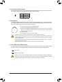
13) CLR_CMOS (Clear CMOS Jumper)
Use this jumper to clear the BIOS congurations and reset the CMOS values to factory defaults. To clear
the CMOS values, use a metal object like a screwdriver to touch the two pins for a few seconds.
• Always turn off your computer and unplug the power cord from the power outlet before clearing the CMOS values.
• After system restart, go to BIOS Setup to load factory defaults (select Load Optimized Defaults) or manually
congure the BIOS settings (refer to Chapter 2, "BIOS Setup," for BIOS congurations).
Open: Normal
Short: Clear CMOS Values

- 16 -
Chapter 2 BIOS Setup
• Because BIOS ashing is potentially risky, if you do not encounter problems using the current version of BIOS,
it is recommended that you not ash the BIOS. To ash the BIOS, do it with caution. Inadequate BIOS ashing
may result in system malfunction.
• It is recommended that you not alter the default settings (unless you need to) to prevent system instability or other
unexpected results. Inadequately altering the settings may result in system's failure to boot. If this occurs, try to
clear the CMOS values and reset the board to default values. (Refer to the "Load Optimized Defaults" section in
this chapter or introductions of the battery/clear CMOS jumper in Chapter 1 for how to clear the CMOS values.)
BIOS (Basic Input and Output System) records hardware parameters of the system in the CMOS on the
motherboard. Its major functions include conducting the Power-On Self-Test (POST) during system startup,
saving system parameters and loading operating system, etc. BIOS includes a BIOS Setup program that allows
the user to modify basic system conguration settings or to activate certain system features.
When the power is turned off, the battery on the motherboard supplies the necessary power to the CMOS to
keep the conguration values in the CMOS.
To access the BIOS Setup program, press the <Delete> key during the POST when the power is turned on.
To upgrade the BIOS, use either the GIGABYTE Q-Flash or @BIOS utility.
• Q-Flash allows the user to quickly and easily upgrade or back up BIOS without entering the operating system.
• @BIOS is a Windows-based utility that searches and downloads the latest version of BIOS from the Internet
and updates the BIOS.
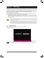
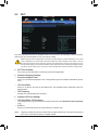
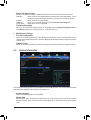
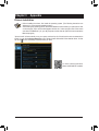
2-1 Startup Screen
The following startup Logo screen will appear when the computer boots.
(Sample BIOS Version: E4)
• When the system is not stable as usual, select the Load Optimized Defaults item to set your system to its defaults.
• The BIOS Setup menus described in this chapter are for reference only and may differ by BIOS version.
Function Keys

- 17 -
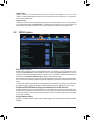
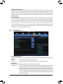
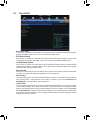
2-2 M.I.T.
This section provides information on the BIOS version, CPU base clock, CPU frequency, memory frequency,
total memory size, CPU temperature, Vcore, and memory voltage.
Whether the system will work stably with the overclock/overvoltage settings you made is dependent on your overall
system congurations. Incorrectly doing overclock/overvoltage may result in damage to CPU, chipset, or memory
and reduce the useful life of these components. This page is for advanced users only and we recommend you not to
alter the default settings to prevent system instability or other unexpected results. (Inadequately altering the settings
may result in system's failure to boot. If this occurs, clear the CMOS values and reset the board to default values.)
` M.I.T. Current Status
This screen provides information on CPU/memory frequencies/parameters.
` Advanced Frequency Settings
& Processor Graphics Clock
Allows you to set the onboard graphics clock. The adjustable range is from 400 MHz to 4000 MHz. (Default:
Auto)
& CPU Clock Ratio
Allows you to alter the clock ratio for the installed CPU. The adjustable range is dependent on the CPU
being installed.
& CPU Frequency
Displays the current operating CPU frequency.
` Advanced CPU Core Settings
& CPU Clock Ratio, CPU Frequency
The settings above are synchronous to those under the same items on the Advanced Frequency Settings
menu.
& K OC
(Note)
Allows for increased performance by using certain CPUs. (Default: Auto)
(Note) This item is present only when you install a CPU that supports this feature. For more information about
Intel
®
CPUs' unique features, please visit Intel's website.

- 18 -
(Note) This item is present only when you install a CPU that supports this feature. For more information about
Intel
®
CPUs' unique features, please visit Intel's website.
& CPU PLL Selection
Allows you to set the CPU PLL. Auto lets the BIOS automatically congure this setting. (Default: Auto)
& Filter PLL Level
Allows you to set the Filter PLL. Auto lets the BIOS automatically congure this setting. (Default: Auto)
& Uncore Ratio
Allows you to set the CPU Uncore ratio. The adjustable range is dependent on the CPU being used.
& Uncore Frequency
Displays the current CPU Uncore frequency.
& Intel(R) Turbo Boost Technology
(Note)
Allows you to determine whether to enable the Intel
®
CPU Turbo Boost technology. Auto lets the BIOS
automatically congure this setting. (Default: Auto)
& Turbo Ratio (1-Core Active~4-Core Active)
(Note)
Allows you to set the CPU Turbo ratios for different number of active cores. Auto sets the CPU Turbo ratios
according to the CPU specications. (Default: Auto)
& Turbo Power Limit (Watts)
Allows you to set a power limit for CPU Turbo mode. When the CPU power consumption exceeds the
specied power limit, the CPU will automatically reduce the core frequency in order to reduce the power.
Auto sets the power limit according to the CPU specications. (Default: Auto)
& Core Current Limit (Amps)
Allows you to set a current limit for CPU Turbo mode. When the CPU current exceeds the specied current
limit, the CPU will automatically reduce the core frequency in order to reduce the current. Auto sets the
power limit according to the CPU specications. (Default: Auto)
& No. of CPU Cores Enabled
(Note)
Allows you to select the number of CPU cores to enable in an Intel
®
multi-core CPU (the number of CPU
cores may vary by CPU). Auto lets the BIOS automatically congure this setting. (Default: Auto)
& Hyper-Threading Technology
(Note)
Allows you to determine whether to enable multi-threading technology when using an Intel
®
CPU that
supports this function. This feature only works for operating systems that support multi-processor mode.
Auto lets the BIOS automatically congure this setting. (Default: Auto)
& CPU Enhanced Halt (C1E)
(Note)
Enables or disables Intel
®
CPU Enhanced Halt (C1E) function, a CPU power-saving function in system
halt state. When enabled, the CPU core frequency and voltage will be reduced during system halt state to
decrease power consumption. Auto lets the BIOS automatically congure this setting. (Default: Auto)
& C3 State Support
(Note)
Allows you to determine whether to let the CPU enter C3 mode in system halt state. When enabled, the
CPU core frequency and voltage will be reduced during system halt state to decrease power consumption.
The C3 state is a more enhanced power-saving state than C1. Auto lets the BIOS automatically congure
this setting. (Default: Auto)
& C6/C7 State Support
(Note)
Allows you to determine whether to let the CPU enter C6/C7 mode in system halt state. When enabled, the
CPU core frequency and voltage will be reduced during system halt state to decrease power consumption.
The C6/C7 state is a more enhanced power-saving state than C3. Auto lets the BIOS automatically congure
this setting. (Default: Auto)
& CPU Thermal Monitor
(Note)
Enables or disables Intel
®
CPU Thermal Monitor function, a CPU overheating protection function. When
enabled, the CPU core frequency and voltage will be reduced when the CPU is overheated. Auto lets the
BIOS automatically congure this setting. (Default: Auto)

- 19 -
(Note 1) This item is present only when you install a CPU that supports this feature. For more information about
Intel
®
CPUs' unique features, please visit Intel's website.
(Note 2) This item is present only when you install a memory module that supports this feature.
` Advanced Memory Settings
& ExtremeMemoryProle(X.M.P.)
(Note 2)
, System Memory Multiplier, Memory Frequency(MHz)
The settings above are synchronous to those under the same items on the Advanced Frequency Settings
menu.
& Memory Boot Mode
Provides memory detection and training methods.
Auto Lets BIOS automatically congure this setting. (Default)
Enable Fast Boot Skip memory detection and training in some specic criteria for faster memory
boot.
Disable Fast Boot Detect and train memory at every single boot.
& Memory Initialization Mode
Allows you to congure memory timing prole for different frequency memory. Options are: Auto (default),
Normal Speed, High Speed, Extreme Speed.
& Memory Enhancement Settings
Provides three different memory performance enhancement settings:
Normal (basic performance), Enhanced Stability, and Enhanced Performance. (Default: Normal)
& Memory Timing Mode
Manual and Advanced Manual allows the Channel Interleaving, Rank Interleaving, and memory timing
settings below to be congurable. Options are: Auto (default), Manual, Advanced Manual.
& ProleDDRVoltage
When using a non-XMP memory module or ExtremeMemoryProle(X.M.P.) is set to Disabled, the value
is displayed according to your memory specication. When ExtremeMemoryProle(X.M.P.) is set to
Prole1 or Prole2, the value is displayed according to the SPD data on the XMP memory.
& Channel Interleaving
Enables or disables memory channel interleaving. Enabled allows the system to simultaneously access
different channels of the memory to increase memory performance and stability. Auto lets the BIOS
automatically congure this setting. (Default: Auto)
& CPU EIST Function
(Note 1)
Enables or disables Enhanced Intel
®
SpeedStep Technology (EIST). Depending on CPU loading, Intel
®
EIST technology can dynamically and effectively lower the CPU voltage and core frequency to decrease
average power consumption and heat production. Auto lets the BIOS automatically congure this setting.
(Default: Auto)
& ExtremeMemoryProle(X.M.P.)
(Note 2)
Allows the BIOS to read the SPD data on XMP memory module(s) to enhance memory performance when
enabled.
Disabled Disables this function. (Default)
Prole1 Uses Prole 1 settings.
Prole2
(Note)
Uses Prole 2 settings.
& System Memory Multiplier
Allows you to set the system memory multiplier. Auto sets memory multiplier according to memory SPD
data. (Default: Auto)
& Memory Frequency (MHz)
The rst memory frequency value is the normal operating frequency of the memory being used; the second
is the memory frequency that is automatically adjusted according to the System Memory Multiplier settings.

- 20 -
& Rank Interleaving
Enables or disables memory rank interleaving. Enabled allows the system to simultaneously access different
ranks of the memory to increase memory performance and stability. Auto lets the BIOS automatically
congure this setting. (Default: Auto)
` Channel A/B Memory Sub Timings
This sub-menu provides memory timing settings for each channel of memory. The respective timing setting
screens are congurable only when Memory Timing Mode is set to Manual or Advanced Manual. Note: Your
system may become unstable or fail to boot after you make changes on the memory timings. If this occurs,
please reset the board to default values by loading optimized defaults or clearing the CMOS values.
` Advanced Voltage Settings
This sub-menu allows you to set CPU and memory voltages.
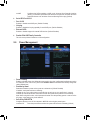
` PC Health Status
& Reset Case Open Status
Disabled Keeps or clears the record of previous chassis intrusion status. (Default)
Enabled Clears the record of previous chassis intrusion status and the Case Open eld will
show "No" at next boot.
& Case Open
Displays the detection status of the chassis intrusion detection device attached to the motherboard CI
header. If the system chassis cover is removed, this eld will show "Yes", otherwise it will show "No". To
clear the chassis intrusion status record, set Reset Case Open Status to Enabled, save the settings to
the CMOS, and then restart your system.
& CPU Vcore/CPU VRIN/DRAM Voltage/+3.3V/+5V/+12V/CPU VAXG
Displays the current system voltages.
& CPU/System Temperature
Displays current CPU/system temperature.
& CPU/System Fan Speed
Displays current CPU/system fan speeds.
& CPU/System Temperature Warning
Sets the warning threshold for CPU/system temperature. When CPU/system temperature exceeds
the threshold, BIOS will emit warning sound. Options are: Disabled (default), 60
o
C/140
o
F, 70
o
C/158
o
F,
80
o
C/176
o
F, 90
o
C/194
o
F.
& CPU/System Fan Fail Warning
Allows the system to emit warning sound if the fan is not connected or fails. Check the fan condition or fan
connection when this occurs. (Default: Disabled)
& CPU Fan Speed Control
Allows you to determine whether to enable the fan speed control function and adjust the fan speed.
Normal Allows the fan to run at different speeds according to the CPU temperature. You can
adjust the fan speed with EasyTune based on your system requirements. (Default)
Silent Allows the fan to run at slow speeds.
Manual Allows you to control the fan speed under the Fan Speed Percentage item.
Full Speed Allows the fan to run at full speeds.
& Fan Speed Percentage
Allows you to control the fan speed. This item is congurable only when CPU Fan Speed Control is set
to Manual. Options are: 0.75 PWM value /
o
C ~ 2.50 PWM value /
o
C.
Page is loading ...
Page is loading ...
Page is loading ...
Page is loading ...
Page is loading ...
Page is loading ...
Page is loading ...
Page is loading ...
Page is loading ...
Page is loading ...
Page is loading ...
Page is loading ...
Page is loading ...
-
 1
1
-
 2
2
-
 3
3
-
 4
4
-
 5
5
-
 6
6
-
 7
7
-
 8
8
-
 9
9
-
 10
10
-
 11
11
-
 12
12
-
 13
13
-
 14
14
-
 15
15
-
 16
16
-
 17
17
-
 18
18
-
 19
19
-
 20
20
-
 21
21
-
 22
22
-
 23
23
-
 24
24
-
 25
25
-
 26
26
-
 27
27
-
 28
28
-
 29
29
-
 30
30
-
 31
31
-
 32
32
-
 33
33


Gigabyte GA-H81M-S (rev. 1.0) User manual
- Category
- Motherboards
- Type
- User manual
Ask a question and I''ll find the answer in the document
Finding information in a document is now easier with AI
Related papers
-
Gigabyte GA-H81M-H (REV. 1.0) User manual
-
Gigabyte GA-H81M-S2V User manual
-
-
-
Gigabyte GA-H81M-H Owner's manual
-
-
-
-
Gigabyte GA-H81M-S2PV User manual
-