Spark Modern Fires 91E 3ft Installation guide
- Category
- Fireplaces
- Type
- Installation guide
This manual is also suitable for

SPARK MODERN FIRES
™
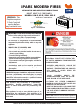
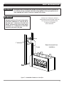
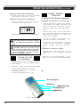
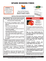
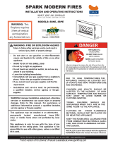
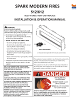
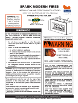
WARNING: This
fireplace requires
2 feet of vertical
venting before
WITH ELECTRONIC IGNITION SYSTEM
SEE THRU
/ P E N I N S U L A
INSTALLATION AND OPERATING INSTRUCTIONS
DIRECT VENT GAS FIREPLACE
S
MODELS: 91N-E, 91P-E, 92N-E, 92P-E
Version française de ce manuel est disponible à partir du site WEB : www.sparkfires.com
– Do not store or use gasoline or other flammable
vapors and liquids in the vicinity of this or any other
appliance.
– WHAT TO DO IF YOU SMELL GAS
department.
– Installation and service must be per formed
by a qualified installer, service agency or the
gas supplier.
This appliance is only for use with the type of gas
indicated on the rating plate. This appliance is not
convertible for use with other gases, unless a certified
kit is used.
INSTALLER: Leave this manual with the appliance.
CONSUMER: Retain this manual for future reference.
This appliance may be installed in an aftermarket,
permanently located, manufactured home
(USA
only)
or mobile home
where not
prohibited by local
codes.
WARNING: FIRE OR EXPLOSION HAZARD
Failure to follow safety warnings exactly could result in
serious injury, death, or property damage.
• Do not touch any electrical switch; do not use any
phone in your building.
• Do not try to light any appliance.
p
hone. Follow the gas supplier's instructions.
• If you cannot reach your gas supplier, call the fire
WARNING: Improper installation, adjustment, alteration,
services or maintenance can cause injury or property
d
amage. Refer to this manual. For assistance or
additional information consult a qualified installer,
service agency or the gas supplier.
C
LOTHING OR OTHER FLAMMABLE
M
ATERIAL SHOULD NOT BE PLACED ON
O
R NEAR THE APPLIANCE.
Y
OUNG CHILDREN SHOULD BE
S
UPERVISED WHEN THEY ARE IN THE
S
AME ROOM AS THE APPLIANCE.
CHILDREN AND ADULTS SHOULD BE
ALERTED TO THE HAZARDS OF HIGH
SURFACE TEMPERATURE AND
SHOULD
STAY AWAY TO AVOID BURNS OR
CLOTHING IGNITION.
DUE TO HIGH TEMPERATURES, THE
APPLIANCE SHOULD BE LOCATED OUT
OF TRAFFIC AND AWAY FROM FURNITURE
AND DRAPERIES.
• Leave the building immediately.
•
Immediately call your gas supplier from a neighbor's
K
EEP THE ROOM AREA CLEARAND
F
REE
FROM COMBUSTIBLE MATERIALS,
G
ASO-
LINE, AND OTHER FLAMMABLE
V
APORS
AND LIQUIDS.
F
rench version of this Owner's Manual is available at www.sparkfires.com
any horizontal runs
Report #
032
1
GF0
0
4S

2
L100001 3
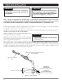
IMPORTANT
This fireplace is designed for a minimum 2 feet of vertical vent pipe rise before any horizontal vent pipe run.
See pages 13-14 for Vent Installation details.
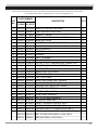
CONTENTS
Important Safety Information .......................... 3
Product Features............................................ 5
Code Approval ................................................ 5
Pre-Installation Information............................. 6
Installing Above 2000 Feet .......................... 6
Orice Sizes, Pressures and BTUs................ 6
Before You Install ........................................ 6
Fireplace Framing ........................................ 7
Fireplace Dimensions .................................. 8
Fireplace Location ....................................... 9
Securing Fireplace to Floor or Framing .......... 10
Clearances................................................... 11
Installation Information................................. 12
Installation Precautions ............................. 13
Installation Planning .................................. 14
Rear Wall Vent Installation ......................... 17
Horizontal Termination Conguration ........... 19
Below Grade Installation ............................ 21
Vertical Through-the-Roof Installation .......... 22
Installation for Vertical Termination..............23
Cathedral Ceiling Installation...................... 24
Fireplace Installation .................................... 25
Check Gas Type ........................................ 25
Installing Gas Piping to Fireplace/Burner
Checking Gas Pressure................................. 27
Electrical Installation.................................... 28
Electrical Wiring ........................................ 28
Wall Switch ............................................... 28
Glass Removal ............................................. 29
Final Installation........................................... 30
Warranty ......................................... Back Cover
Vent Installation ......................................................... 12
Gas Connection .......................................... 26
Media Tray Placement ......................
Operating Instructions .................................. 33
What T
o Do If Y
ou Smell Gas ...........................33
Operating Instructions.................................. 33
.
....... 30
Safety Screen Installation............................ 31
............................................... 38
Stones, Media ........................................... 38
Fan Assembly................................................ 38
Replacement Parts ....................................... 39
Vent Components ...................................... 39
Firebox Components .................................. 40
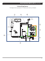
SIT Proflame Wiring Diagram........................ 41
Troubleshooting............................................
43
Pilot Flame .............................................. 37
Burner Flame ........................................... 37
Air Shutter Assembly ................................ 37
Vent System ............................................. 38
Glass Panel
To Turn Of f Gas ......................................... 33
Cleaning and Maintenance............................ 3
7
Burner, Pilot and Control Compar tment ....... 37

2 L100001
3
4. Never install the replace
• in a recreational vehicle
• where curtains, furniture, clothing, or other ammable
objects are less than 42" from the front, top, or sides of
the replace
• in high trafc areas
• in windy or drafty areas
5. This replace reaches high temperatures. Keep children and
adults away from hot surfaces to avoid burns or clothing
ignition. Fireplace will remain hot for a time after shutdown.
Allow surfaces to cool before touching.
6. Carefully supervise young children when they are in the
room with replace.
7. Do not modify replace under any circumstances. Any parts
removed for servicing must be replaced prior to operating
replace.
8. Turn replace off and let cool before servicing, cleaning,
or repairing. Only a qualied service person should install,
service, or repair the replace. Have burner system inspected
annually by a qualied service person.
9. You must keep control compartments, burners, and cir-
culating air passages clean. More frequent cleaning may
be needed due to excessive lint and dust from carpeting,
bedding material, pet hair, etc. Turn off the gas valve and
pilot light before cleaning replace.
10. Have venting system inspected annually by a qualied
service person. If needed, have venting system cleaned or
repaired. See Cleaning and Maintenance, page 37.
11. Keep the area around your replace clear of combustible
materials, gasoline, and other ammable vapor and liquids.
Do not run replace where these are used or stored. Do not
place items such as clothing or decorations on or around
replace.
INSTALLER
Please leave these instructions with the owner.
OWNER
Please retain these instructions for future reference
.
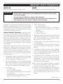
IMPORTANT SAFETY INFORMATION
This replace is a vented product. This replace must be properly
installed by a qualied service person. The glass panel must be
properly seated and sealed. If this unit is not properly installed
by a qualied service person with glass panel properly seated and
sealed, combustion leakage can occur.
CARBON MONOXIDE POISONING: Early signs of carbon
monoxide poisoning are similar to the u with headaches, diz-
ziness and/or nausea. If you have these signs, the replace may
not have been installed properly. Get fresh air at once! Have the
replace inspected and serviced by a qualied service person.
Some people are more affected by carbon monoxide than others.
These include pregnant women, people with heart or lung dis-
ease or anemia, those under the inuence of alcohol, and those
at high altitudes.
Propane/LP gas and natural gas are both odorless. An odor-
making agent is added to each of these gases. The odor helps
you detect a gas leak. However, the odor added to these gases
can fade. Gas may be present even though no odor exists.
Make certain you read and understand all warnings. Keep this
manual for reference. It is your guide to safe and proper opera-
tion of this replace.
1. This appliance is only for use with the type of gas indicated
on the rating plate. This appliance is not convertible for use
with other gases unless a certied kit is used.
2. For propane/LP replace, do not place propane/LP supply
tank(s) inside any structure. Locate propane/LP supply
tank(s) outdoors. To prevent performance problems, do not
use propane/LP fuel tank of less than 100 lbs. capacity.
3. If you smell gas
• shut off gas supply
• do not try to light any appliance
• do not touch any electrical switch; do not use any phone
in your building
• immediately call your gas supplier from a neighbor’s
phone. Follow the gas supplier’s instructions.
Continued on page 4
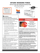
• Read this owner’s manual carefully and completely before trying to assemble, operate,
or service this fireplace.
• Any change to this fireplace or its controls can be dangerous.
• Improper installation or use of this fireplace can cause serious injury or death from fire,
burns, explosions, electrical shock
o r
carbon monoxide poisoning.
WARNING

4
L100001 5
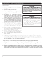
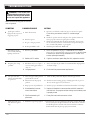
IMPORTANT SAFETY INFORMATION
Continued from page 3
12. Do not use this replace to cook food or burn paper or
other objects.
13. Never place anything on top of replace.
14. Do not use any solid fuels (wood, coal, paper, cardboard,
etc.) in this replace. Use only the gas type indicated on
rating plate.
15. This appliance, when installed, must be electrically
grounded in accordance with local codes or in the absence
of local codes, with the National Electrical Code, ANSI/
NFPA 70, or the Canadian Electrical Code, CSA C22.1.
16. Do not obstruct the ow of combustion and ventilation air
in any way. Provide adequate clearances around air open-
ings into the combustion chamber along with adequate
accessibility clearance for servicing and proper operation.
17. When the appliance is installed directly on carpeting, tile
or other combustible material other than wood ooring,
you must set appliance on a metal or wood panel or hearth
pad extending the full width and depth of the appliance.
18. Do not use replace if any part has been exposed to or
has been under water. Immediately call a qualied service
person to arrange for replacement of the unit.
IMPORTANT:
PLEASE READ THE FOLLOWING CAREFULLY
It is normal for fireplaces fabricated of steel to give off some
expansion and/or contraction noises during the start up or
cool down cycle. Similar noises are found with your furnace
heat exchanger or car engine.
IMPORTANT:
PLEASE READ THE FOLLOWING CAREFULLY
It is not unusual for a gas fireplace to give off some
odor the first time it is burned. This is due to the
manufacturing process.
Please ensure that your room is well ventilated
during burn off — open all windows.
It is recommended that you burn your fireplace for at least
ten (10) hours the first time you use it. Place the fan switch
in the “OFF” position during this time.
19. Do not use a blower insert, heat exchanger insert, or any
other accessory not approved for use with this replace.
20. Do not operate the replace with glass panel removed,
cracked, or broken.
21. Young children should be carefully supervised when they are in the same room as the appliance. Toddlers, young children,
and others may be susceptible to accidental contact burns. A physical barrier is recommended if there are at risk individuals
in the house. To restrict access to a fireplace or stove, install an adjustable safety gate to keep toddlers, young children, and
other at risk individuals out of the room and away from hot surfaces.
22. Any safety screen or guard removed for servicing an appliance must be replaced prior to operatingthe appliance.
Handle glass door with care to avoid striking or scratching it on hard objects. WARNING: Do not operate appliance with
the glass front removed, cracked or broken. Replacement of the glass should be done by a licensed or qualified service
person.
23.
24. Installation and repair should be done by a qualified service person. The appliance should be inspectedbefore use and at least
annually by a profesional service person. More frequent cleaning may be requireddue to excessive lint from carpeting, bedding
material, etc. It is imperative that control compartments,burners and circulating air passageway of the appliance be kept clean.

4 L100001
5
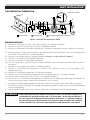
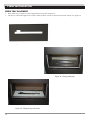
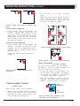
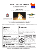
PRODUCT FEATURES AND CODE APPROVAL
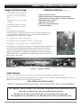
Figure 1 - Fireplace controls
• This appliance has been certied
for use with either natural or
propane gas. See appropriate data
plates.
• This appliance is not for use with
solid fuels.
• The appliance is approved for bed-
room or bedsitting room installa-
tions.
PRODUCT SPECIFICATIONS FIREPLACE CONTROLS
(see Figure 1)
1
1
2
2
3
3
4
5
6
7
1- Remote Control Receiver
2- Blower Speed Control with Manual On/Off Switch
3- Power Outlet to Connect Blower or Optional AUX Block
4-
Gas Manual Shut-Off Valve
5- Main Gas Control Valve
7- Thermostat Blower
6-
Electronic Control DFC Board
CSA B149.1 in Canada.
• The installation must conform
with local codes or, in the absenceof local codes, with the NationalFuel Gas
Code, ANSI
Z223.1/NFPA54 in U.S.A., or the NaturalGas and Propane
Installation Code,
• This appliance is mobile homeapproved.
• The appliance must be properlyconnected to a venting system.
• The appliance is not approved forcloset or recessed installations.
• This appliance is mobile home approved. A manufactured home (USA o
nly) or
mobile home OEM installation
must conform with the Manufactured Home
Construction and Safety Standard, Title 24 CFR, Part 3280, or, whensuch a
standard is not applicable, the Standard for Manufactured Home Installations,
ANSI/NCSBS A225.1, orStandard for Gas Equiped Recreational Vehicles and
Mobile House, CSA Z240.4.
TESTED TO: ANSI Z21.88-2014/CSA 2.33-2014, CGA 2.17-M91 (R2009), CSA P.4.1-09 STANDARDS
LISTED VENTED GAS FIREPLACE HEATER
Direct Vent type appliances draw all combustion air from outside of the dwelling through the vent pipe.
CODE APPROVAL
These appliances have been listed by OMNI and found to comply with the established standards for DIRECT VENT GAS
FIREPLACE HEATERS in the USA and Canada as follows:
This appliance may be installed in an aftermarket, permanently located, manufactured home
(USA only) or mobile home, where not prohibited by local codes.
This appliance is only for use with the type of gas indicated on the rating plate.
This appliance is not convertible for use with other gases, unless a certified kit is used.

6
L100001 7
PRE-INSTALLATION INFORMATION
INSTALLING ABOVE 2000 FEET
• In the USA, the appliance must be derated 4% for every 1,000 ft above 2,000 ft elevations (at the factory).
• In Canada, these appliances are certied for altitudes of 0 – 4,500 ft.
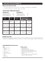
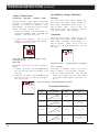
ORIFICE SIZES, PRESSURES AND BTUs
NATURAL GAS PROPANE GAS
Manifold Press: (W.C.) 3.5" Manifold Press: (W.C.) 10"
Maximum Supply Pressure 10.5" Maximum Supply Pressure 13"
Minimum Supply Pressure 4.5" Minimum Supply Pressure 11"
BEFORE YOU START
Read this homeowner'smanual thoroughly and follow all instructions carefully. Inspect all contents for shipping damage and
immediately inform Spark Modern if any damage is found. Do not install any unit with damaged, incomplete, or substitute parts.
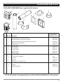
ITEMS REQUIRED FOR INSTALLATION
Tools: Building Supplies:
• Phillips Screwdriver • Framing Materials
• Hammer • Wall Finishing Materials
• Saw and/or saber saw • Caulking Material (Non-combustible)
• Level • Fireplace Surround Material (Non-combustible)
• Measuring Tape • Piping Complying with Local Codes
• Electric Drill and Bits • Tee Joint
• Pliers • Pipe Sealant Approved for use with Propane/LPG
• Square (Resistant to Sulfur Compounds)
• Pipe Wrench
Model Gas Orifice Size
Input Rate, Btu/hr
Number Type As Shipped
Max Min
91N-E - SeeThru Natural #31 39,000 27,000
91P-E
- SeeThru Propane #49 38,000 27,000
92N-E - Peninsula Natural #31 39,000 27,000
92P-E
- Peninsula Propane #49 38,000 27,000

L100001 9
7
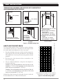
PRE-INSTALLATION INFORMATION
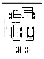
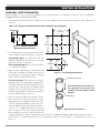
Figure 2 - Fireplace Dimensions
MODEL 91/92
FRONT VIEW
24"
24"
22.5"
24"
MODEL 91
MODEL 92
32"
22.50"
41.75"
52.50"
32"
7.5"
17"
7.5"
40"
13"
17"
36.33"
SIDE VIEW
TOP VIEW
SIDE VIEW
DIRECT VENT GAS FIREPLACE DIMENSIONS

8 L100001
8
PRE-INSTALLATION INFORMATION
FIREPLACE LOCATION
Plan for the installation of your appliance. This includes determining where the unit is to be installed, the vent configuration to be
used, framing and finishing details, and whether any optional accessories (i.e. wall switch, or remote control) are desired.
Consult your local building code agency to ensure compliance with local codes, including permits and inspections.
The following factors should be taken into consideration:
• Clearance to side-wall, ceiling, woodwork, and windows. Minimum clearances to combustibles must be maintained.
• Location should be out of high traffic areas and away from furniture and draperies due to heat from appliance.
• Never obstruct the front opening of the fireplace.
• Do not install in the vicinity where gasoline or other flammable liquids may be stored.
• Vent pipe routing. See Venting section in this manual for allowable venting configurations.
• These units can be installed in a bedroom or bathroom. See National Fuel Gas Code ANSI Z233.1/NFPA 54 (current edition),
the Uniform Mechanical Code — (current edition), and Local Building Codes for specific installation requirements.
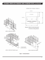
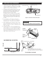
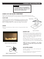
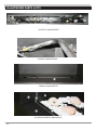
PLANING FIREPLACE FRAMING AND COVERING FACE
Firebox framing can be built before or after the appliance is set in place. Construct rebox framing following Figure 3 and the
chart below for your specic installation requirements. See Figure 2 on Page 7 for rebox dimensions. The framing headers may
rest on the top of the rebox standoff.
The rebox may be installed directly on a combustible oor or raised on a platform of an appropriate height. When the rebox
is installed directly on carpeting, tile, or other combustible material, other than wood ooring, the rebox shall be installed on a
metal or wood panel extending the full width and depth of the enclosure.
Do not fill spaces around firebox with insulation
or other materials. This could cause a fire.
WARNING
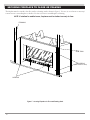
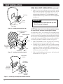
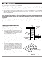
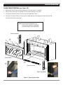
IMPORTANT: The following must be taken into consideration if
you decide to cover over the fireplace face:
1. The covering material must be non combustible, maximum 3/4" thick.
2. Minimum outside dimensions of the material over the facing are
41-3/4" x 40" (see Figure 4 on Pge 9).
3. The inner opening in covering material must be minimum 36-1/2" wide, 18" tall and centered over the fireplace opening to allow
for glass door removal.
4. The cover should maintain an air gap of at least 1/8" between covering material and fireplace to allow for metal fireplace front
to expand and contract during operation.
5. PLEASE NOTE: Natural stone products may react to heat by discoloring or cracking. Spark Modern Fires is not resposible for
any damages due to covering materials used. If tiles are to be applied covering the fireplace face, a layer of cement board mustany damages due to covering materials used. If tiles are to be applied covering the fireplace face, a layer of cement board must
be used as a substrate.

6 L100001
9
PLANING FIREPLACE FRAMING AND COVERING FACE (continued)
-5 - For more information, visit www.desatech.com
Figure 4 - Minimum outside dimensions
of the face covering material

10
L100001 11
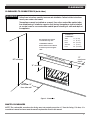
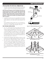
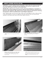
The replace must be secured to the oor and/or to framing studs as shown in Figure 5. Use two (2) wood screws or masonry/
concrete screws to secure replace to the oor. Use four (4) screws to attach replace to framing.
SECURING FIREPLACE TO FLOOR OR FRAMING
Figure 5 - Securing Fireplace to Floor and Framing Studs
SCREWS
SCREWS
SIDE TABS
(TWO ON EACH SIDE)
FRAMING
NOTE: If installed in mobile home, fireplace must be bolted securely to floor

10 L100001
11
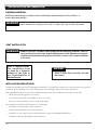
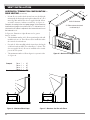
CLEARANCES
CLEARANCES TO COMBUSTIBLES (both sides)
MANTEL CLEARANCES
NOTE: The combustible area above the facing must not protrude more than
3
/4" from the facing. If it does, it is
considered a mantel and must meet the mantel requirements listed in this manual.
Figure 6 - Clearances
Follow these instructions carefully to ensure safe installation. Failure to follow instructions
exactly can create a fire hazard.
The appliance cannot be installed on a carpet, tile or other combustible material other
than wood flooring. If installed on carpet or vinyl flooring, the appliance shall be installed
on a metal, wood or
non-
combustible material panel extending full width and depth of
the appliance.
WARNING
The fireplace face may be
covered with any non-
combustible material.
Allow clearance for removal
of front air panel and glass
6
6
6
6
6
6
6
6
14" minimum
90" minimum
Minimum 12"
from side wall
12"
maximum
depth
COMBUSTIBLE MANTEL
door.
Front 36"
(915 mm)
Standoff 0"
(0 mm)
Back 0.5" (13 mm)
Floor 0"
(0 mm)
(0 mm)
Sides 0"
Combustibles
Clearance to

12
L100001 13
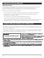
INSTALLATION PRECAUTIONS
Consult local building codes before beginning the installation. The installer must make sure to select the proper vent system for
installation. Before installing vent kit, the installer must read this replace manual and vent kit instructions.
Only a qualied installer/service person should install venting system. The installer must follow these safety rules:
• Wear gloves and safety glasses for protection.
• Use extreme caution when using ladders or when on rooftops.
• Be aware of electrical wiring locations in walls and ceilings.
The following actions will void the warranty on your fireplace:
• Installation of any damaged venting component.
• Unauthorized modication of the venting system.
• Installation of any component part not manufactured or approved by Spark Modern Fires.
• Installation other than permitted by these instructions.
FINISHING MATERIAL
NOTE: Any remote wiring (i.e. remote control or wall switch) must be done prior to fina finishin to
avoid costly reconstruction.
INSTALLATION INFORMATION
VENT INSTALLATION
Never obstruct or modify the air inlet or outlet. This may create a fire hazard.
WARNING
Read all instructions completely and thoroughly before attempting installation. Failure to
do so could result in serious injury, property damage or loss of life. Operation of improperly
installed and maintained venting system could result in serious injury, property damage
or loss of life.
Failure to follow these instructions will void
the warranty.
NOTICE
WARNING
State of Massachusetts:
The installation must
be done by a licensed
plumber or gas fitter in
the Commonwealth of
Massachusetts.

12 L100001
13
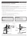
VENT INSTALLATION
Figure 7 - Combustible Clearances for Vent Pipe
A Minimum of 4" Clearance to the Top Is
Required Along Horizontal Length of Pipe until
Flue Pipe Goes Through Nearest Wall.
WARNING
This fireplace must be vented to the outside. The venting system must NEVER be attached
to a chimney serving a separate solid-fuel burning appliance. Each gas appliance must
use a separate vent system. Do not use common vent systems.
WARNING
Horizontal sections of this vent system require
a minimum clearance of 4" from the top of
the pipe and 1" minimum to the sides and
bottom. Vertical sections of this system require
a minimum of 1" clearance to combustible
materials on all sides of the pipe.
WARNING
1" Clearance Is Acceptable
at the Outside Wall.
6
6
4" minimum
1" minimum
2' pipe
Basic Horizontal Vent
Installation

14
L100001 15
VENT INSTALLATION
INSTALLATION PLANNING
There are two basic types of direct-vent installation:
• Horizontal Termination
• Vertical Termination
It is important to select the proper length of vent pipe for the type of termination you choose. It is also important to note the
wall thickness.
FOR HORIZONTAL TERMINATION
Select the amount of vertical rise desired. All horizontal run of venting
must have
1
/4" rise for every 12" of run towards the termination.
You may use up to three 90° elbows in this vent conguration. See
Horizontal Termination Congurations on pages 19 and 20.
FOR VERTICAL TERMINATION
Measure the distance from the replace oor to the ceiling. Add the ceiling thickness, the vertical rise in an attic or second story,
and allow for sufcient vent height above the roof line.
NOTE: You may use two 45° elbows in place of a 90° elbow. You must follow rise to run ratios when using 45° elbows.
The appliance is approved for use with three 90° elbows maximum or a combination of 90° and 45° elbows up to a
maximum of 270°.
For two-story applications, restops are required at each oor level. If an offset is needed in the attic, additional pipe and elbows
will be required.
You may use a chase with a vent termination with exposed pipe on the exterior of the house. See Installing Vent System in a Chase
below. If pipe is enclosed in chase, it is not exposed.
It is very important that the venting system maintain its balance between the combustion air intake and the ue gas exhaust.
Certain limitations apply to vent congurations and must be strictly followed.
INSTALLING A VENT SYSTEM IN AN OUTSIDE CHASE
A chase is a vertical boxlike structure built to enclose venting that runs along the outside of a building. A chase is required for
such venting.
Never run the vent pipe level or downward.
This may cause excessive temperatures which
could cause a fire
.
WARNING
When installing in a chase, you should insulate the chase as you would the outside walls of
your home. This is especially important in cold climates. Insulation should be considered
a combustible material. Maintain proper clearances to all combustible materials.
NOTICE
Treatment of firestops and construction of the chase may vary from building type to
building type. These instructions are not substitutes for the requirements of local building
codes. You must follow all local building codes.
NOTICE

14 L100001
15
VENT INSTALLATION
Figure 8 - Horizontal Vent Termination Location
Vent Terminal Air Supply Inlet Area Where Terminals Not Permitted
Inside Corner Detail
FOR HORIZONTAL TERMINATION
MINIMUM DISTANCES
A = Clearance above the grade, a veranda, porch, deck, or balcony [*12" (305mm) minimum].
B = Clearance to window or door that may be opened [*12" (305mm) minimum].
C = Clearance to permanently closed window [*minimum 12" (305mm) recommended to prevent condensation on window]
D
= Vertical clearance to ventilated soft located above the terminal within a horizontal distance of two (2) feet (610mm) from
the centerline of the terminal [18" (457mm) minimum].
E
= Clearance to unventilated softs [12" (305mm) minimum]. Clearance to vinyl soft [30" (762mm)].
F = Clearance to an outside corner [*6" (152mm) minimum].
G = Clearance to an inside corner [*6" (152mm) minimum .]
H = *Not to be installed above a gas meter/regulator assembly within three (3) feet (914mm) horizontally from the centerline of
the regulator.
I = Clearance to service regulator vent outlet [*3' (914mm) minimum].
J = Clearance to non-mechanical air supply inlet to building or the combustion air inlet to any other appliance [*12"
(305mm) minimum].
K = Clearance to a mechanical air supply inlet [*6' (1829mm) minimum].
L
= Clearance above a paved sidewalk or paved driveway located on public property [
**
7' (2133mm) minimum].
M
= Clearance under veranda, porch, deck, or balcony [*12" (305mm) minimum
***
].
N = Clearance above a roof shall extend a minimum of 24" (610mm) above the highest point when it passes through the roof
surface and any other obstruction within a horizontal distance of 18" (457mm).
* As specied in CAN/CGA B149 Installation Codes. Note: Local codes or regulations may require different clearances.
** A vent must not terminate directly above a sidewalk or paved driveway, which is located between two single-family dwellings
and serves both dwellings.
*** Only permitted if veranda, porch, deck, or balcony is fully open on a minimum of two sides beneath the oor.
Always maintain minimum clearances around vent systems. The minimum clearances to
combustibles for horizontal vent pipe are 4" at the top and 1" at the sides and bottom of
the vent system until the pipe penetrates the nearest vertical wall. A 1" minimum clearance
all around the pipe must be maintained. Do not pack the open air spaces with insulation
or other materials. This could cause high temperatures and may present a fire hazard.
WARNING

16
L100001 17
12305
2305
12305
VENT INSTALLATION
TERMINATION CLEARANCES FOR BUILDINGS WITH COMBUSTIBLE
AND NONCOMBUSTIBLE EXTERIORS
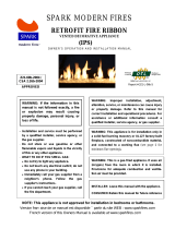
Figure 9 - Allowable Venting Chart
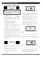
HOW TO USE THE VENT GRAPH
The Vent Graph should be read in conjunction with the following
vent installation instructions to determine the relationship between
the vertical and horizontal dimensions of the vent system.
1. Determine the height of the center of the horizontal vent pipe exit-
ing through the outer wall. Using this dimension on the Sidewall
Vent Graph below, locate the point intersecting with the slanted
graph line.
2. From the point of this intersection, draw a vertical line to the
bottom of the graph.
3. Select the indicated dimension, and position the replace in
accordance with same.
Example: If the vertical dimension from the floor of the
fireplace is 11' (
3.4 m
) the horizontal run to the face of the
outer wall must not exceed
17
' (5.25 m).
Example: If the vertical dimension from the floor of the unit
is 7’ (
2.14 m
), the horizontal
wall must not exceed
12
' (
2.67
m).
run to the face of the outer
Sidewall Vent Graph showing the relationship between vertical and
horizontal dimensions for a Direct Vent ue system.
Figure 10 - Rear Wall Venting Graph
Horizontal Dimension (Ft) From the Outside of
Termination to the Back of the Fireplace
Vertical Dimension (Ft) From the Floor of Unit to the Center of
the Horizontal Vent Pipe
50
48
44
46
40
38
36
42
24
20
22
32
26
30
28
34
6
4
2
14
10
12
8
16
18
0
0 2 4 6 12108 14 2418 20 2216

16 L100001
17
Figure 12 - Vent Opening Requirements
Note: Horizontal runs of vent must
be supported every three feet
(914mm). Use wall straps for this
purpose.
Figure 13 - Rigid Vent Pipe Connections
Female Locking Lugs
Male Slots
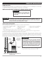
REAR WALL VENT INSTALLATION
When installed as a rear vent unit this appliance may be vented directly to a termination located on the rear wall behind
the appliance with 2' of vertical rise minimum.
• The maximum horizontal distance between the rear of the appliance and the outside of termination is 20" (508 mm). See
Figure 11.
• NOTE: A 30° elbow on 2 foot minimum vertical pipe is required for this configuration.
VENTING INSTALLATION
1. Locate and cut the vent opening in the wall. For com-
bustible walls rst frame in opening. See Figure 11.
Combustible Walls: Cut a 9
1
⁄2" H x 9
1
⁄2" W
(241mm x 241mm) hole through the exterior wall
and frame as shown. See Figure 12.
Noncombustible Walls: Hole opening should be
7
1
⁄2" (190mm) in diameter.
2. Rigid vent pipes and ttings have special twist-lock
connections. Assemble the desired combination of
pipe and elbows to the appliance adaptor with pipe
seams oriented towards the wall or oor.
Twist-lock Procedure:
The female ends of the pipes
and ttings have three locking lugs (indentations).
These lugs will slide straight into matching slots on
the male end of adjacent pipes and ttings. Push
the pipe sections together and twist one section
clockwise approximately one-quarter turn until the
sections are fully locked. See Figure 13.
3. Attach vent pipe assembly to the replace. Set re-
place in front of its permanent location to insure
minimum clearances. Mark the wall for a 9
1
⁄2"H
x 9
1
⁄2"W (241mm x 241 mm) square hole (for
noncombustible material such as masonry block or
concrete, a 7
1
/2" [190mm] diameter hole is accept-
able). See Figure 11. The center of the hole should
line up with the center line of the horizontal rigid
vent pipe end. Be sure to allow for minimum rise. Cut a 9
1
/2"x9
1
/2" (241mm X 241mm) square hole through combustible
exterior wall (7
1
/2" [190mm] diameter hole if noncombustible). Frame as necessary. Allow
1
/4" minimum rise per foot. See
Figure 12.
Figure 11 - Rear Vent Application,
Maximum Horizontal Distance
Maximum
20"

18
L100001 19
HOT
HOT
VENT INSTALLATION
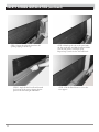
4. Apply a bead of non-hardening mastic around the outside
edge of vent cap. Position the vent cap in the center of hole
on the exterior wall with the arrow up on the vent cap.
Insure proper clearance of 1" to combustibles is main-
tained. Attach the vent cap with four wood screws supplied.
See Figure 14.
NOTE: Replace the wood screws with appropriate fasteners
for stucco, brick, concrete, or other types of siding.
For vinyl siding, stucco, or wood exterior use vinyl siding stand-
offs between vent cap and exterior wall. The vinyl siding standoff
prevents excessive heat from melting the vinyl siding material. Bolt
the vent cap to the standoff. Apply non-hardening mastic around
outside edge of the standoff instead of the vent cap assembly. Use
wood screws provided to attach the standoff. See Figure 15.
5. Slide the wall thimble over the vent pipe before connecting
the horizontal run to the vent cap. See Figure 16.
6. Carefully move the replace with vent assembly attached
toward the wall and insert the vent pipe into the horizontal
termination. The pipe overlap should be a minimum of 1
1
/4".
Apply silicone to the outer pipe connection. Fasten all vent
connections with screws provided.
7. Slide the wall thimble against the interior wall surface and
attach with srews. See Figure 16.
Figure 14 - Installing Horizontal Vent Cap
REAR WALL VENT INSTALLATION (continued)
Figure 15 - Installing Vinyl Siding Standoff
Apply Mastic
to All Four
Sides
Vent Cap
Wood
Screw
Cut Vinyl Siding Away to
Fit Standoff
Wood Screw
Vent Cap
Bolt
Apply Mastic to All
Four Sides
Nut
Standoff
Figure 16 - Connecting Vent Cap with Horizontal Vent Pipe
Interior Wall
Surface
Decorative
Wall Thimble
Horizontal
Vent Pipe
Screw
Vent Cap
(Horizontal
Termination)
Deflecting Shield
Do not recess vent termination into any wall.
This will cause a fire hazard.
WARNING
S

18 L100001
19
VENT INSTALLATION
HORIZONTAL TERMINATION CONFIGURATIONS — RIGID VENTING
Since it is very important that the venting system maintain its balance between the combustion air intake and the ue gas
exhaust, certain limitations as to vent congurations apply and must be strictly adhered to.
The Vent Graph, showing the relationship between vertical and horizontal side wall venting, will help to determine the various
dimensions allowable. See page 16.
Minimum clearance between vent pipes and combustible materials is 4" on top and 1" from bottom and sides unless
otherwise noted.
When vent terminations exit through foundations less than 20" below siding outcrop, the vent pipe must ush up with the sid-
ing.
It is best to locate the replace in such a way that minimizes the number of offsets and horizontal vent length.
The horizontal vent run refers to the total length of vent pipe from the ue collar of the replace (or the top of the Transition
Elbow) to the face of the outer wall.
Figure 18 - Maximum Three (3) 90 Elbows
Per Installation
• The maximum number of 90° elbows per side wall installation is three (3), the maximum horizontal run is 20" (Figures 18, 19)
Figure 19 - Maximum Horizontal Run with 2 foot rise
20"
Max.
Rise 2' min
The Commonwealth of Massachusetts requires the installation and USE of Carbon Monoxide detectors
in the rooms of ALL direct vent units which utilize a SIDE WALL VENTING TERMINATION
FOR STATE OF MASSACHUSETTS:
3 x 90
o
Elbows

20
L100001 21
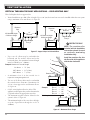
• If a 90° elbow is used in the horizontal vent run (level height
maintained) the horizontal vent length is reduced by 36" (914
mm) (Fig. 20 A and B) This does not apply if the 90° elbows
are used to increase or redirect a vertical rise. See Figure 19.
Example: According to the vent graph (page 16) the maximum
horizontal vent length in a system with a 7.5' vertical rise is 15’
(6m) and if a 90° elbow is required in the horizontal vent it must
be reduced to 12'.
In Figure 20, Dimension A plus B must not be greater
than 12' (3.66m).
• The maximum number of 45° elbows permitted per side wall
installation is two (2). These elbows can be installed in either
the vertical or horizontal run.
• For each 45° elbow installed in the horizontal run, the length
of the horizontal run MUST be reduced by 18" (45cm). This
does not apply if the 45° elbows are installed on the vertical
part of the vent system.
• The maximum number of elbow degrees in a system is 270°.
See Figure 22.
Figure 21 - Maximum Vent Run with Elbows
Figure 20 - Maximum Vent Run with Elbows
Figure 22 - Maximum Elbow Usage
VENT INSTALLATION
1 + 2 + 3 + 4 = 270°
1
2
3
1
2
3
4
HORIZONTAL TERMINATION CONFIGURATION —
RIGID VENTING (Continued)
Example: Elbow 1 = 90°
Elbow 2 = 45°
Elbow 3 = 45°
Elbow 4 = 90°
Total Angular Variation = 270°
7'6"
8'
4'
A
B
90° Elbow reduces horizontal
run allowed by 3'.
A+B=12' Maximum.
Page is loading ...
Page is loading ...
Page is loading ...
Page is loading ...
Page is loading ...
Page is loading ...
Page is loading ...
Page is loading ...
Page is loading ...
Page is loading ...
Page is loading ...
Page is loading ...
Page is loading ...
Page is loading ...
Page is loading ...
Page is loading ...
Page is loading ...
Page is loading ...
Page is loading ...
Page is loading ...
Page is loading ...
Page is loading ...
Page is loading ...
Page is loading ...
Page is loading ...
Page is loading ...
Page is loading ...
Page is loading ...
-
 1
1
-
 2
2
-
 3
3
-
 4
4
-
 5
5
-
 6
6
-
 7
7
-
 8
8
-
 9
9
-
 10
10
-
 11
11
-
 12
12
-
 13
13
-
 14
14
-
 15
15
-
 16
16
-
 17
17
-
 18
18
-
 19
19
-
 20
20
-
 21
21
-
 22
22
-
 23
23
-
 24
24
-
 25
25
-
 26
26
-
 27
27
-
 28
28
-
 29
29
-
 30
30
-
 31
31
-
 32
32
-
 33
33
-
 34
34
-
 35
35
-
 36
36
-
 37
37
-
 38
38
-
 39
39
-
 40
40
-
 41
41
-
 42
42
-
 43
43
-
 44
44
-
 45
45
-
 46
46
-
 47
47
-
 48
48


Spark Modern Fires 91E 3ft Installation guide
- Category
- Fireplaces
- Type
- Installation guide
- This manual is also suitable for
Ask a question and I''ll find the answer in the document
Finding information in a document is now easier with AI
Related papers
-
 Spark Modern Fires 48E 4ft Installation guide
-
 Spark Modern Fires 49E 4ft Installation guide
-
 Spark Modern Fires 88E 3ft Installation guide
-
Spark Modern Fires LBS-OD 24 Installation guide
-
Spark Modern Fires Slim 46 DV Stainless Surrond Installation guide
-
 Spark Modern Fires FT60 5ft Installation guide
-
 Spark Modern Fires 612E 6ft Installation guide
-
 Spark Modern Fires 19E 6ft Installation guide
-
 Spark Modern Fires 34ST Stainless Steel Installation guide
-
 Spark Modern Fires LBS36E 3ft Installation guide


Other documents
-
 Spark 91N Installation And Operating Instructions Manual
-
American Hearth Boulevard Direct-Vent Linear See- Through Fireplace (DVLL48SP) Owner's manual
-
Desa Tech DVFE41 User manual
-
-
White Mountain Hearth Boulevard Direct-Vent Linear See-Through Fireplace (DVLL48SP) Owner's manual
-
-
FMI BDV34PA User manual
-
-
-
