Premier Mounts ECM-3763S Specification
- Category
- Flat panel ceiling mounts
- Type
- Specification
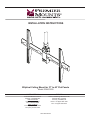
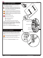
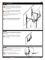
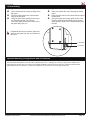
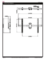
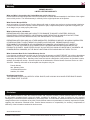
Premier Mounts ECM-3763S is an elliptical ceiling mount designed for flat-panel displays ranging from 37 to 63 inches. Its durable construction supports up to 175 lbs, making it suitable for various commercial and residential applications. The mount allows for 360-degree swivel and 15-degree tilt, providing flexible viewing angles. It features integrated cable management to keep installation neat and organized. Additionally, the mount includes optional brackets for mini PCs and digital media players, making it ideal for digital signage solutions.
Premier Mounts ECM-3763S is an elliptical ceiling mount designed for flat-panel displays ranging from 37 to 63 inches. Its durable construction supports up to 175 lbs, making it suitable for various commercial and residential applications. The mount allows for 360-degree swivel and 15-degree tilt, providing flexible viewing angles. It features integrated cable management to keep installation neat and organized. Additionally, the mount includes optional brackets for mini PCs and digital media players, making it ideal for digital signage solutions.


-
 1
1
-
 2
2
-
 3
3
-
 4
4
-
 5
5
-
 6
6
-
 7
7
-
 8
8
-
 9
9
-
 10
10
-
 11
11
-
 12
12
-
 13
13


Premier Mounts ECM-3763S Specification
- Category
- Flat panel ceiling mounts
- Type
- Specification
Premier Mounts ECM-3763S is an elliptical ceiling mount designed for flat-panel displays ranging from 37 to 63 inches. Its durable construction supports up to 175 lbs, making it suitable for various commercial and residential applications. The mount allows for 360-degree swivel and 15-degree tilt, providing flexible viewing angles. It features integrated cable management to keep installation neat and organized. Additionally, the mount includes optional brackets for mini PCs and digital media players, making it ideal for digital signage solutions.
Ask a question and I''ll find the answer in the document
Finding information in a document is now easier with AI
Related papers
-
Premier Mounts ECM-3763Q Specification
-
Premier Mounts USA Installation guide
-
-
-
-
-
Premier Mounts ECM-3763T Specification
-
-
Premier Mounts CPD10WALLARM User manual
-
Premier Mounts EST250 Owner's manual
Other documents
-
Simpli Home AXSS008KDW Installation guide
-
Strong SM-FIXPOLE-24-WH Owner's manual
-
-
-
-
-
OmniMount 60-841 Datasheet
-
 Commercial Electric 31903 Installation guide
-
LG PCM-MS2 User manual
-
Premier GB-MS1 Specification
