Page is loading ...

36V LITHIUMTRIMMER / EDGER
INSTRUCTION MANUAL
Model Number LST136
PLEASE READ BEFORE RETURNING
THIS PRODUCT FOR ANY REASON:
Ifyou have a question or experience a problem with your
Black & Decker purchase, go to
WWW.BLACKAN DDECKER.COM/INSTANTANSWERS
for instant answers 24 hours a day.
Ifyou can't find the answer or do not have access to the internet,
call 1-800-544-6986 from 8 a.m. to 5 p.m. EST Mon. - Fri
to speak with an agent.
Please have the catalog number available when you call.
SAVETHIS MANUAL FOR FUTURE REFERENCE.
VEA EL ESPANOL EN LA CONTRAPORTADA.
POUR LE FRAN_AIS, VOIR LA COUVERTURE ARRI#RE.
IN.STRUCTIVO DE O.PERACION, CENTROS DE SERVICIO Y
POLIZA DE GARANTIA. ADVERTENClA: LI_ASE ESTE
INSTRUCTIVO ANTES DE USAR EL PRODUCTO.
1
Model # LST136
KEY INFORMATION YOU SHOULD KNOW:
The guard must be installed before trimming or edging - if
not, the motor will overheat (page 8).
When replacing the line, use only .065 inch diameter
ROUND line (B&D Model #AF-100 is recommended) -
otherwise the tool will not function properly (page 11).
Do not bump the feed head against the ground - it will
disrupt the feed mechanism.
SafetyGuidelines-Definitions.................................................2
ImportantSafetyWarningsandInstructions............................2
Components.............................................................................4
ImportantSafetyInstructionsforBatteryChargers..................4
ImportantSafetyInstructionsforBatteryPacks.......................5
Assembly/ Adjustment ............................................................. 8
Operating Instructions .............................................................. 9
Replacement Accessories ........................................................ 10
Maintenance ............................................................................ 12
Troubleshooting ....................................................................... 12
Service Information .................................................................. 13
Full Three-Year Home Use Warranty ....................................... 15
SAFETY GUIDELINES - DEFINITIONS
It is important for you to read and understand this manual. The
information it contains relates to protecting YOUR SAFETY and
PREVENTING PROBLEMS. The symbols below are used to help
you recognize this information.
_DANGER: Indicates an imminently hazardous situation which,
not avoided, will result in death or serious injury.
_WARNING: Indicates a potentially hazardous situation which, i
not avoided, could result in death or serious injury.
z_CAUTION: Indicates a potentially hazardous situation which, if
not avoided, may result in minor or moderate injury.
NOTICE: Used without the safety alert symbol indicates a
potentially hazardous situation which, if not avoided, may result in
property damage.
z_WARNING: When using electric gardening appliances, basic
safety precautions should always be followed to reduce risk of fire,
electric shock, and personal injury, including the following.
Read All Instructions
• ALWAYS WEAR EYE PROTECTION - Wear safety spectacles
or goggles at all times when this toot is plugged in.
• GUARD - Do not use this tool without guard attached.
• DRESS PROPERLY - Do not wear loose clothing or jewelry.
They can be caught in moving parts. Rubber gloves and
substantial rubber soled footwear are recommended when
working outdoors. Don't operate the toot when barefoot or
wearing open sandals. Wear heavy long pants to protect your
legs. Wear protective hair covering to contain tong hair.
• NYLON LINE - Keep face, hands and feet clear of rotating nylon
line at all times.
• THE ROTATING LINE PERFORMS A CUTTING FUNCTION -
Use care when trimming around screens and desirable plantings.
• KEEP ALL BYSTANDERS AWAY - at a safe distance from
work area, especiatlychitdren.
• IMPORTANTWARNING - When being used as an Edger,
stones, pieces of metal and other objects can be thrown out at
high speed by the line. The toot and guard are designed to
reduce the danger. However, the following special precautions
should be taken:
•MAKESURE thatotherpersonsandpetsare atleast100feet (30m)away.
• TO REDUCE THE RISK of rebound (ricochet) injury, work going
away from any nearby solid object such as watt, steps, large
stone, tree, etc. Use great care when working close to solid
objects and where necessary, do edging or trimming by hand.
• AVOID ACCIDENTALLY STARTING - Don t carry plugged-in
tool with finger on trigger.
• DO NOT FORCE THETOOL - at a rate faster than the rate at

whichitisabletocuteffectively.
•USETHERIGHTTOOL- Donotusethistootforanyjobexcept
thatforwhichitisintended.
•DON'TOVERREACH- Keepproperfootingandbalanceatalltimes.
DAMAGETOUNIT- Ifyoustrikeorbecomeentangledwitha
foreignobject,stoptoolimmediately,unplug,checkfordamage
andhaveanydamagerepairedbeforefurtheroperationis
attempted.Donotoperatewithabrokenhuborspool.
•DISCONNECTTOOL-whennotinuse,whenreplacingline,or
priortocleaning.
•AVOIDDANGEROUSENVIRONMENTALCONDITIONS- Do
notuseelectrictoolsindamporwetlocations.Followall
instructionsinthisInstructionManualforproperoperationofyour
tool.Don'tusethetootintherain.
•DONOTOPERATEportableelectrictoolsingaseousor
explosiveatmospheres.Motorsinthesetoolsnormallyspark,and
thesparksmightignitefumes.
•STOREIDLETOOLSINDOORS-Whennotinuse,toolsshouldbe
storedindoorsinadry,locked-upplaceoutofreachofchildren.
•STAYALERT- Donotoperatethisunitwhenyouaretired,ill,
orundertheinfluenceofalcohol,drugs,ormedication.
•MAINTAINAPPLIANCESWITHCARE- Followinstructionsin
maintenancesection.Keephandlesdry,cleanandfreefromoil
andgrease.
•CHECKDAMAGEDPARTS- Beforefurtheruseofthe
appliance,aguardorotherpartthatisdamagedshouldbe
carefullycheckedtodeterminethatitwiltoperateproperlyand
performitsintendedfunction.Checkforalignmentofmoving
parts,bindingofmovingparts,breakageofparts,mounting,and
anyotherconditionthatmayaffectitsoperation.Aguardorother
partthatisdamagedshouldbeproperlyrepairedorreplacedby
anauthorizedservicecenterunlessotherwiseindicated
elsewhereinthismanual.
•DONOTimmersetoolinwaterorsquirtitwithahose.DONOT
allowanyliquidtogetinsideit.
•DONOTstorethetootonoradjacenttofertilizersorchemicals.
•DONOTcleanwithapressurewasher.
Keepguardsinplaceandinworkingorder.
•Keephandsandfeetawayfromcuttingarea.
Z_WARNING: Do not use toot if the switch trigger does not turn
the toot on or off. Any toot that can not be controlled with the switch
trigger is dangerous and must be repaired.
SAVE THESE INSTRUCTIONS
The label on your toot may include the following symbols. The
symbols and their definitions are as follows:
V .............. volts A ................ amperes
Hz ............ hertz W................ watts
min ............ minutes ,x, .............. alternating current
- - -. ......... direct current no .............. no load speed
[] .............. Class II Construction @ ............ earthing terminal
Z_ ............safety alert symbol
.../min ......revolutions or
reciprocations per minute
_WARNING: Some dust created by this product contains
chemicals known to the State of California to cause cancer,
birth defects or other reproductive harm. Some examples of
these chemicals are:
• compounds in fertilizers
• compounds in insecticides, herbicides and pesticides
• arsenic and chromium from chemically treated lumber
To reduce your exposure to these chemicals, wear approved safety
equipment such as dust masks that are specially designed to filter out
microscopic particles.
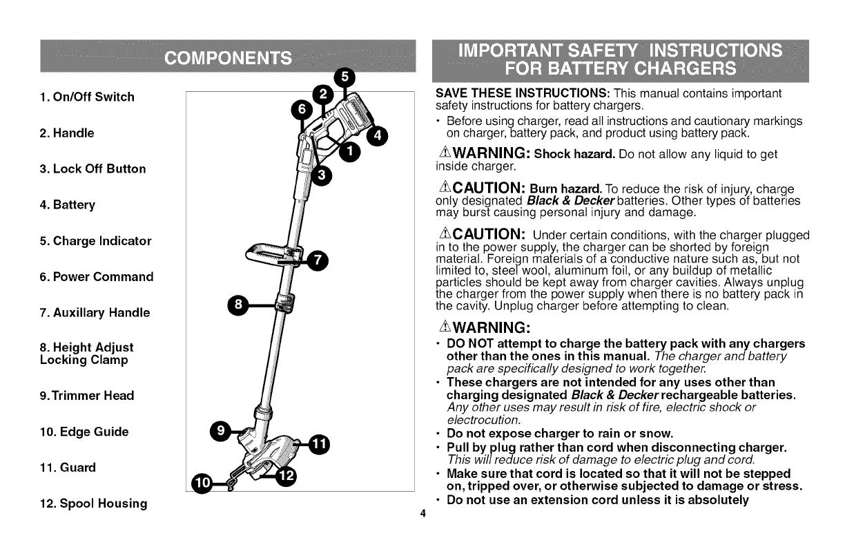
1. On/Off Switch
2. Handle
3. Lock Off Button
4. Battery
5. Charge Indicator
6. Power Command
7. Auxiliary Handle
8. Height Adjust
Locking Clamp
9.Trimmer Head
10. Edge Guide
11. Guard
12. Spool Housing
4
SAVE THESE INSTRUCTIONS: This manual contains important
safety instructionsfor battery chargers.
• Before using charger, read all instructions and cautionary markings
on charger, battery pack, and product using battery pack.
z_WARNING: Shock hazard. Do not allow any liquid to get
inside charger.
Z_CAUTION: Burn hazard. To reduce the risk of injury, charge
only designated Black & Decker batteries. Other types of batteries
may burst causing personal injury and damage.
z_CAUTION: Under certain conditions, with the charger plugged
in to the power supply, the charger can be shorted by foreign
material. Foreign materials of a conductive nature such as, but not
limited to, steelwoot, aluminum foil, or any buildup of metallic
particles should be kept away from charger cavities. Always unplug
the charger from the power supply when there is no battery pack in
the cavity. Unplug charger before attempting to clean.
_WARNING:
• DO NOT attempt to charge the battery pack with any chargers
other than the ones in this manual. The charger and battery
pack are specifically designed to work together.
• These chargers are not intended for any uses other than
charging designated Black & Decker rechargeable batteries.
Any other uses may result in risk of fire, electric shock or
electrocution.
Do not expose charger to rain or snow.
Pull by plug rather than cord when disconnecting charger.
This will reduce risk of damage to electric plug and cord.
Make sure that cord is located so that it will not be stepped
on, tripped over, or otherwise subjected to damage or stress.
Do not use an extension cord unless it is absolutely
necessary. Use of improper extension cord could result in risk of
fire, electric shock, or electrocution.
• An extension cord must have adequate wire size (AWG or
American Wire Gauge) for safety. The smaller the gauge number
of the wire, the greater the capacity of the cable, that is 16 gauge
has more capacity than 18 gauge. When using more than one
extension to make up the total length, be sure each individual
extension contains at least the minimum wire size.
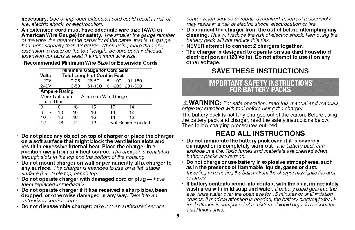
Recommended Minimum Wire Size for Extension Cords
Minimum Gauge for Cord Sets
Volts Total Length of Cord in Feet
120V 0-25 26-50 51-100 101-150
240V 0-50 51-100 101-200 201-300
Ampere Rating
More Not more American Wire Gauge
Than Than
0 6 18 16 16 14
6 10 18 16 14 12
10 - 12 16 16 14 12
12 - 16 14 12 Not Recommended
• Do not place any object on top of charger or place the charger
on a soft surface that might block the ventilation slots and
result in excessive internal heat. Place the charger in a
position away from any heat source. The charger is ventilated
through slots in the top and the bottom of the housing.
• Do not mount charger on wall or permanently affix charger to
any surface. The charger is intended to use on a flat, stable
surface (i.e., table top, bench top).
• Do not operate charger with damaged cord or plug -- have
them replaced immediately.
• Do not operate charger if it has received a sharp blow, been
dropped, or otherwise damaged in any way. Take it to an
authorized service center.
• Do not disassemble charger; take it to an authorized service
center when service or repair is required. Incorrect reassembly
may result in a risk of electric shock, electrocution or fire.
• Disconnect the charger from the outlet before attempting any
cleaning. This will reduce the risk of electric shock. Removing the
battery pack will not reduce this risk.
• NEVER attempt to connect 2 chargers together.
• The charger is designed to operate on standard household
electrical power (120 Volts). Do not attempt to use it on any
other voltage.
SAVE THESE INSTRUCTIONS
z_WARNING: For safe operation, read this manual and manuals
originally supplied with tool before using the charger.
The battery pack is not fully charged out of the carton. Before using
the battery pack and charger, read the safety instructions below.
Then follow charging procedures outlined.
READ ALL INSTRUCTIONS
• Do not incinerate the battery pack even if it is severely
damaged or is completely worn out. The battery pack can
explode in a fire. Toxic fumes and materials are created when
battery packs are burned.
• Do not charge or use battery in explosive atmospheres, such
as in the presence of flammable liquids, gases or dust.
Inserting or removing the battery from the charger may ignite the dust
or fumes.
• If battery contents come into contact with the skin, immediately
wash area with mild soap and water, ffbattery liquid gets into the
eye, rinse water over the open eye for 15 minutes or until irritation
ceases. If medical attention is needed, the battery electrolyte for Li-
ion batteries is composed of a mixture of liquid organic carbonates
and lithium salts.

• Contentsof opened batterycells maycause respiratory irritation.
Provide freshair.Ifsymptomspersist, seekmedical attention.
ZLWARNING: Burn hazard. Battery liquid may be flammable if
exposed tospark or flame.
• Charge the batterypacks onlyin Black & Decker chargers.
• DO NOT splash or immerse in water or other liquids. This may
cause premature cell failure.
• Do not store or use the tool and battery pack in locations where
the temperature may reach or exceed 105°F (40°0) (such as
outside sheds or metal buildings in summer).
ZLWARNING: Never attempt to open the battery pack for any
reason. If battery pack case is cracked or damaged, do not insert into
charger. Do not crush, drop or damage battery pack. Do not use a
battery pack or charger that has received a sharp blow, been
dropped, run over or damaged in any way (i.e., pierced with a nail,
hit with a hammer, stepped on). Damaged battery packs should be
returned to service center for recycling.
zLWAR NIN G: Firehazard. Do notstoreor carry batteryso that
metal objects can contactexposed batteryterminals. For example,do
not place battery in aprons,pockets, toolboxes,product kitboxes,drawers,
etc., withloose nails,screws, keys,etc.Transporting batteries can possibly
cause fires if the battery terminals inadvertently come in contact with
conductive materials such as keys, coins, hand tools and the like. The
US Department of TransportationHazardous Material Regulations (HMR)
actuallyprohibit transportingbatteries in commerce or on airplanes (i.e.,
packed in suitcases and carry-onluggage) UNLESS they areproperly
protectedfrom short circuits.So when transportingindividualbatteries, make
sure that the battery terminals areprotected and wellinsulatedfrom materials
thatcould contact them and causea short circuit.NOTE:Batteries should
not be put in checked baggage.
STORAGE RECOMMENDATIONS
1. The best storage place is one that is coot and dry away from
direct sunlight and excess heat or cold.
2. Long storage will not harm the battery pack or charger.
CHARGING PROCEDURE
The standard charger provided will charge a fully depleted battery in
about 2 hours.
1. Plug the charger intoan appropriate outlet before inserting the
battery pack.
2. Insert the battery pack into the charger _1
as shown in figure A.
3. The green LED will flash
indicating that the battery is being
charged.
_4. The completion of charge is
indicated by the green LED
remaining on continuously. The pack
isfully charged and may be used at
this time or left on the charger.
Recharge discharged batteries as soon
as possible after use or battery life may be greatly diminished.
CHARGER DIAGNOSTICS
This charger is designed to detect certain problems that can arise
with the battery packs or the power source. Problems are indicated
by one LED flashing in different patterns.
BAD BATTERY
_The charger can detect a weak or damaged battery. The red
LED flashes in the pattern indicated on the label. If you see
this bad battery blink pattern, do not continue to charge the
battery. Return it to a service center or a collection site for
recycling.
HOT/COLD PACK DELAY
_When the charger detects a battery that is excessively hot or
excessively cold, it automatically starts a Hot/Cold Pack
Delay, suspending charging until the battery has normalized.
After this happens, the charger automatically switches to the
Pack Charging mode. This feature ensures maximum battery
life. The red LED flashes in the pattern indicated on the label
when the hot / cold pack delay is detected.
LEAVINGTHEBATTERYINTHECHARGER
Thechargerandbatterypackcanbeleftconnectedwiththegreen
LEDglowingindefinitely.Thechargerwiltkeepthebatterypack
freshandfullycharged.
IMPORTANTCHARGINGNOTES
1.Longestlifeandbestperformancecanbeobtainedifthebattery
packischargedwhentheairtemperatureisbetween60°Fand
80°F(16°-27°C).DONOTchargethebatterypackinanair
temperaturebelow+40°F(+4.5°C),orabove+105°F(+40.5°C).
Thisisimportantandwillpreventseriousdamagetothebattery
pack.
2.Thechargerandbatterypackmaybecomewarmtotouchwhile
charging.Thisisanormalcondition,anddoesnotindicatea
problem.Tofacilitatethecoolingofthebatterypackafteruse,avoid
placingthechargerorbatterypackinawarmenvironmentsuchas
inametalshed,oranuninsulatedtrailer.
3.Ifthebatterypackdoesnotchargeproperly:
a.Checkcurrentatreceptaclebyplugginginalamporother
appliance
b.Checktoseeifreceptacleisconnectedtoalightswitch
whichturnspoweroffwhenyouturnoutthelights.
c.Movechargerandbatterypacktoalocationwherethe
surroundingairtemperatureisapproximately60°F-80°F
(16°-27°C).
d.Ifchargingproblemspersist,takethetoot,batterypackand
chargertoyourlocalservicecenter.
4.Thebatterypackshouldberechargedwhenitfailstoproduce
sufficientpoweronjobswhichwereeasilydonepreviously.DONOT
CONTINUEtouseundertheseconditions.Followthecharging
procedure.Youmayalsochargeapartiallyusedpackwhenever
youdesirewithnoadverseaffectonthebatterypack.
5.Foreignmaterialsofaconductivenaturesuchas,butnotlimited
to,steelwool,aluminumfoil,oranybuildupofmetallicparticles
shouldbekeptawayfromchargercavities.Alwaysunplugthe
chargerfromthepowersupplywhenthereisnobatterypackinthe
cavity.Unplugchargerbeforeattemptingtoclean.
6.Donotfreezeorimmersechargerinwateroranyotherliquid.
zLWARNING: Shock hazard. Do not allow any liquid to get
inside charger. Never attempt to open the battery pack for any
reason. If the plastic housing of the battery pack breaks or cracks,
return to a service center for recycling.
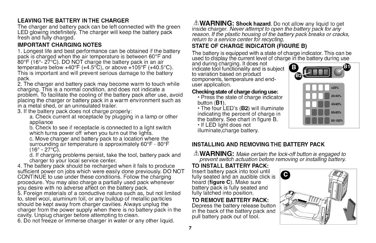
STATE OF CHARGE INDICATOR (FIGURE B)
The battery is equipped with a state of charge indicator. This can be
used to display the current level of charge in the battery during use
and during charging. It does not
indicate toot functionality and is subject
to variation based on product
components, temperature and end-
user application.
Checking state of charge during use:
• Press the state of charge indicator
button (B1).
• The four LED's (B2) wilt illuminate
indicating the percent of charge in
the battery. See chart in figure B.
• If LED light does not
illuminate,charge battery.
INSTALLING AND REMOVING THE BATTERY PACK
ZLWARNING: Make certain the Iock-off button b engaged to
prevent switch actuation before removing or installing battery.
TO INSTALL BATTERY PACK:
Insert battery pack into toot until
fully seated and an audible click is
heard (figure C). Make sure
battery pack is fully seated and
fully latched into position.
TO REMOVE BATTERY PACK:
Depress the battery release button
in the back of the battery pack and
pull battery pack out of toot.

Z_WARNING: Before assembly, make sure that the toot is
switched off and the battery has been removed.
ASSEMBLYTOOLS REQUIRED (NOT SUPPLIED):
- Phillips Screwdriver
z_WARNING: Remove the
battery before attempting to
attach any of the following
components.
ATTACHING THE GUARD
(FIGURES D AND E)
Z_WARNING: NEVER
OPERATE TOOL
WITHOUT GUARD FIRMLY
IN PLACE. The guard must
always be properly attached
on the toot to protect the user.
• Remove the screw from
the guard.
• Keeping the guard square
to the trimmer head slide it
into place until the retaining
tab clicks into place (Ensure
that the guide rails (D1) on
the guard (D2) are correctly
aligned with the guide rails
(D3) on the trimmer head
(D4) (figure D).
• Secure the guard with the
screw (El) (figure E).
ATTACHING THE AUXILIARY HANDLE (FIGURES F AND G)
• Push the auxiliary handle
(F1) onto the tube (F2).
• Slide the bolt (G1) through
the holes in the auxiliary
handle.
• Tighten the knob (G2) onto
the bolt by turning it
clockwise.
\\\
ADJUSTINGTHEPOSITIONOFTHEAUXILIARYHANDLE
(FIG.G)
The auxiliary handle can be
adjusted to provide optimum
balance and comfort.
• Loosen the knob on the
bolt by turning it counter
clockwise.
• Gently slide the auxiliary
handle up or down the tube
to the desired height.
• Tighten the knob onto the
bolt by turning it clockwise.
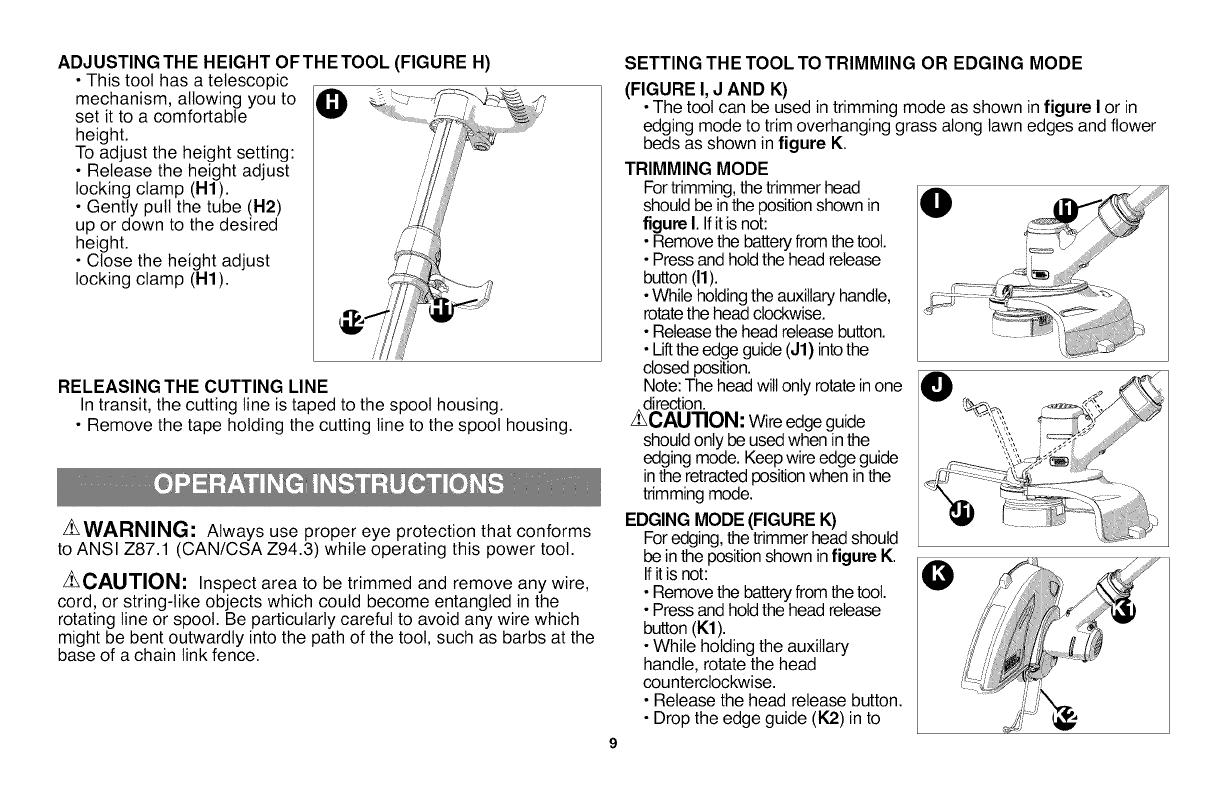
ADJUSTINGTHEHEIGHTOFTHETOOL(FIGUREH)
• This toot has a telescopic
mechanism, allowing you to
set it to a comfortable
height.
To adjust the height setting:
• Release the height adjust /
locking clamp (H1).
• Gently putt the tube (H2)
up or down to the desired
height.
• Close the height adjust
locking clamp (H1).
RELEASING THE CUTTING LINE
In transit, the cutting line is taped to the spool housing.
• Remove the tape holding the cutting line to the spool housing.
Z_WARNING: Always use proper eye protection that conforms
to ANSI Z87.1 (CAN/CSA Z94.3) while operating this power toot.
Z_CAUTION: Inspect area to be trimmed and remove any wire,
cord, or string-like objects which could become entangled in the
rotating line or spool. Be particularly careful to avoid any wire which
might be bent outwardly into the path of the toot, such as barbs at the
base of a chain link fence.
SETTING THE TOOL TO TRIMMING OR EDGING MODE
(FIGURE I, J AND K)
• The toot can be used in trimming mode as shown in figure I or in
edging mode to trim overhanging grass along lawn edges and flower
beds as shown in figure K.
TRIMMING MODE
For trimming,the trimmer head
should be inthe positionshown in
figure I.Ifitis not:
• Remove the batteryfrom the toot.
• Pressand holdthe head release
button (11).
•While holdingthe auxiliaryhandle,
rotatethe head clockwise.
• Releasethe head release button.
• Liftthe edge guide(J1) intothe
closed position.
Note: The head willonly rotatein one
direction.
z_CAUTION: Wireedgeguide
shouldonly be usedwhen in the
edging mode. Keepwire edge guide
in the retractedpositionwhen inthe
trimming mode.
EDGING MODE (FIGURE K)
For edging,the trimmer head should
be inthe positionshown infigure K.
Ifitis not:
• Remove the batteryfrom the toot.
• Pressand holdthe head release
button (K1).
• While holding the auxiliary
handle, rotate the head
counterclockwise.
• Release the head release button.
• Drop the edge guide (K2) in to
theopenposition.Ensurethattheedgingguideisallthewaydown,
anaudibleclickwiltbeheard.
Note:Theheadwillonlyrotateinonedirection.
Note:TheAutoFeedSystemmaynotoperatecorrectlyifedgeguide
isnotused.
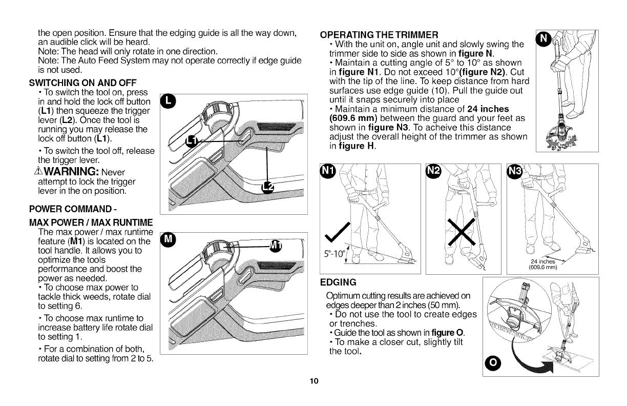
SWITCHINGONAND OFF
•To switch the toot on, press
in and hold the lock off button
(L1) then squeeze the trigger
lever (L2). Once the tool is
running you may release the
lock off button (L1).
•To switch the toot off, release
the trigger lever.
z_WARNING: Never
attempt to lock the trigger
lever inthe on position.
POWER COMMAND-
MAX POWER / MAX RUNTIME
The max power / max runtime
feature (M1)is located on the
tool handle. Itallows you to
optimize the tools
performance and boost the
power as needed.
•To choose max power to
tackle thick weeds, rotate dial
to setting 6.
•To choose max runtime to
increase battery life rotate dial
to setting 1.
• For a combination of both,
rotate dialto setting from 2 to 5.
OPERATING THE TRIMMER
• With the unit on, angle unit and slowly swing the
trimmer side to side as shown in figure N.
• Maintain a cutting angle of 5° to 10° as shown
in figure N1. Do not exceed 10°(figure N2). Cut
with the tip of the line. To keep distance from hard
surfaces use edge guide (10). Pull the guide out
until it snaps securely into place
• Maintain a minimum distance of 24 inches
(609.6 ram) between the guard and your feet as
shown in figure N3. To acheive this distance
adjust the overall height of the trimmer as shown
in figure H.
EDGING
Optimum cuttingresultsare achievedon
edges deeperthan 2inches (50mm).
• Do not use the toot to create edges
or trenches.
• Guidethe tool asshown infigure O.
• To make a closer cut, slightly tilt
the toot.
(609.6 mm)
lO
HELPFUL CUTTING TIPS
• Use the tip of the string to do the cutting; do not force string
head into uncut grass. Use edge guide along such things as
fences, houses and flower beds for best practices.
• Wire and picket fences cause extra string wear, even breakage.
Stone and brick walls, curbs, and wood may wear string rapidly.
• Do not allow spool cap to drag on ground or other surfaces.
• In tong growth cut from the top down and do not exceed 12
inches (304.8 mm) high.
• Keep trimmer tilted toward the area being cut; this is the best
cutting area.
•The trimmer cuts when passing the unit from the right to left.
This wilt avoid throwing debris at the operator.
•Avoid trees and shrubs. Tree bark, wood moldings, siding, and
fence posts can easily be damaged by the string.
CUTTING LINE / LINE FEEDING
Your trimmer uses .065 inch (1.65 ram) diameter, ROUND
nylon line. During use, the tips of the nylon lines wilt become
frayed and worn and the special self feeding spool wilt
automatically feed and trim a fresh length of line. DO NOT BUMP
unit on ground in attempt to feed line or for any other purposes.
Cutting line will wear faster and require more feeding if the
cutting or edging is done along sidewalks or other abrasive
surfaces or heavier weeds are being cut.
ZLCAUTION: Before you begin trimming, only use the
appropriate type of cutting line.
Use Black & Decker replacement spool Model No. AF-100.
• USE ONLY .065 inch (1.65 mm) DIAMETER ROUND NYLON
MONOFILAMENT LINE. Do not use serrated or heavier gauge
line, as they will overload the motor and cause overheating.
• Other replacement parts (guards, spool caps, etc.) are available
11
through Black & Decker service centers. To find your local service
location call: 1-800-544-6986
or visit
www.blackanddecker.com. _
_WARNING: The use of
any accessory not Replacement
recommended by Black & spool
Decker for use with this toot
could be hazardous.
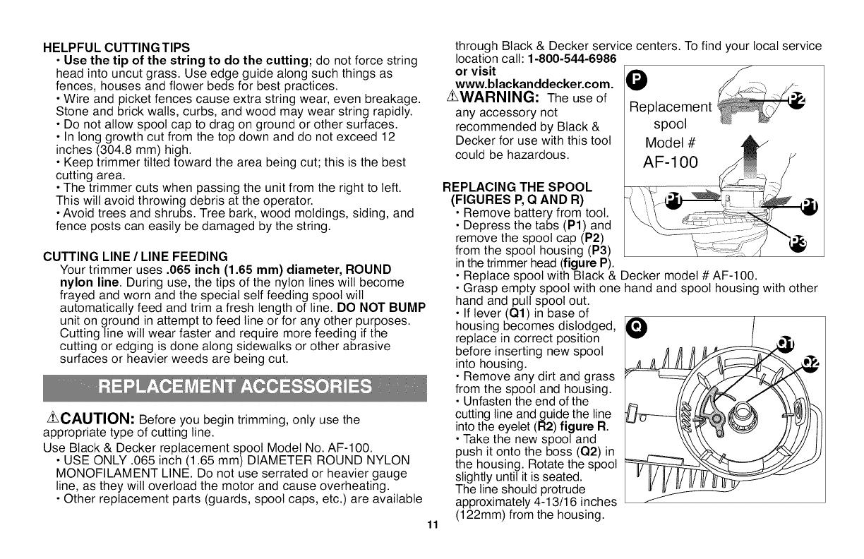
REPLACING THE SPOOL
(FIGURES P,Q AND R)
• Remove battery from toot.
• Depress the tabs (P1) and
remove the spool cap (P2)
from the spool housing (P3)
in the trimmer head (figure P).
• Replace spool with Black & Decker model # AF-100.
• Grasp empty spool with one hand and spool housing with other
hand and pull spool out.
• If lever (Q1) in base of
housing becomes dislodged,
replace in correct position
before inserting new spool
into housing.
• Remove any dirt and grass
from the spool and housing.
• Unfasten the end of the
cutting line and guide the line
into the eyelet (R2) figure R.
• Take the new spool and
push it onto the boss (Q2) in
the housing. Rotate the spool
slightly until it is seated.
The line should protrude
approximately 4-13/16 inches
(122mm) from the housing.
O
Ii
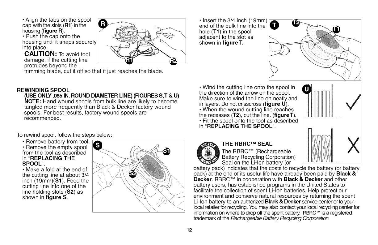
• Align the tabs on the spool JAil, _ - Insert the 3/4 inch (19mm)
cap with the slots (R1) inthe _,_ _ _ / end of the bulk line into the
housing (figure R). / [_'L'/_=:_ __._._ hole (T1) in the spool
• Push the cap onto the ___/_. _<:_' ",J adjacent to the slot as
housing until it snaps securely shown in figure T.
into place. _ _ ._d_,
CAUTION: To avoid tool _._ _ "_
damage, if the cutting line _1_[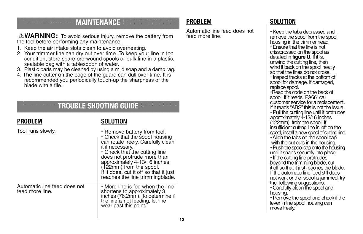
_WARNING: To avoid serious injury, remove the battery from
the tool before performing any maintenance.
1. Keep the air intake slots clean to avoid overheating.
2. Your trimmer line can dry out over time. To keep your line in top
condition, store spare pre-wound spools or bulk line in a plastic,
sealable bag with a tablespoon of water.
3. Plastic parts may be cleaned by using a mild soap and a damp rag.
4. The line cutter on the edge of the guard can dull over time. It is
recommended you periodically touch-up the sharpness of the
blade with a file.
PROBLEM
Toot runs slowly.
Automatic line feed does not
feed more line.
SOLUTION
• Remove battery from toot.
• Check that the spool housing
can rotate freely. Carefully clean
it if necessary.
• Check that the cutting line
does not protrude more than
approximately 4-13/16 inches
(122mm) from the spool.
If it does, cut it off so that it just
reaches the line trimmingblade.
• More line is fed when the line
shortens to approximately 3
inches (76.2mm). To determine if
the line is not feeding, letline
wear past this point.
PROBLEM
Automatic line feed does not
feed more line.
SOLUTION
• Keepthe tabsdepressed and
remove the spoolfrom the spool
housing inthe trimmer head.
• Ensurethat the lineisnot
crisscrossedonthe spool as
detailedin figure U. Ifit is,
unwindthe cuttingline,then
windit back onthe spool neatly
sothatthe linesdo not cross.
• Inspecttracks atthe bottom of
spool fordamage. Ifdamaged,
replace spool.
•Read the code on the back of
spool.Ifitreads "PA66"call
customer servicefor a replacement.
Ifitreads "ABS"this isnot the issue.
• Pullthe cuttingline untilitprotrudes
approximately4-13/16 inches
(122mm) from the spool. If
insufficientcuttinglineis leftonthe
spool,installa newspoolofcutlng line.
•Alignthe tabs on the spoolcap
with the cutouts inthe housing.
• Pushthespoolcapontothe housing
untilitsnaps securelyinto place.
• Ifthe cutting lineprotrudes
beyond the trimming blade,cut
itoffso that itjust reachesthe blade.
Ifthe automaticlinefeed stilldoes
notwork or the spool isjammed, try
the followingsuggestions:
•Carefullyclean the spool and
housing.
• Remove the spool and check if the
leverinthe spool housing can
move freely.
13
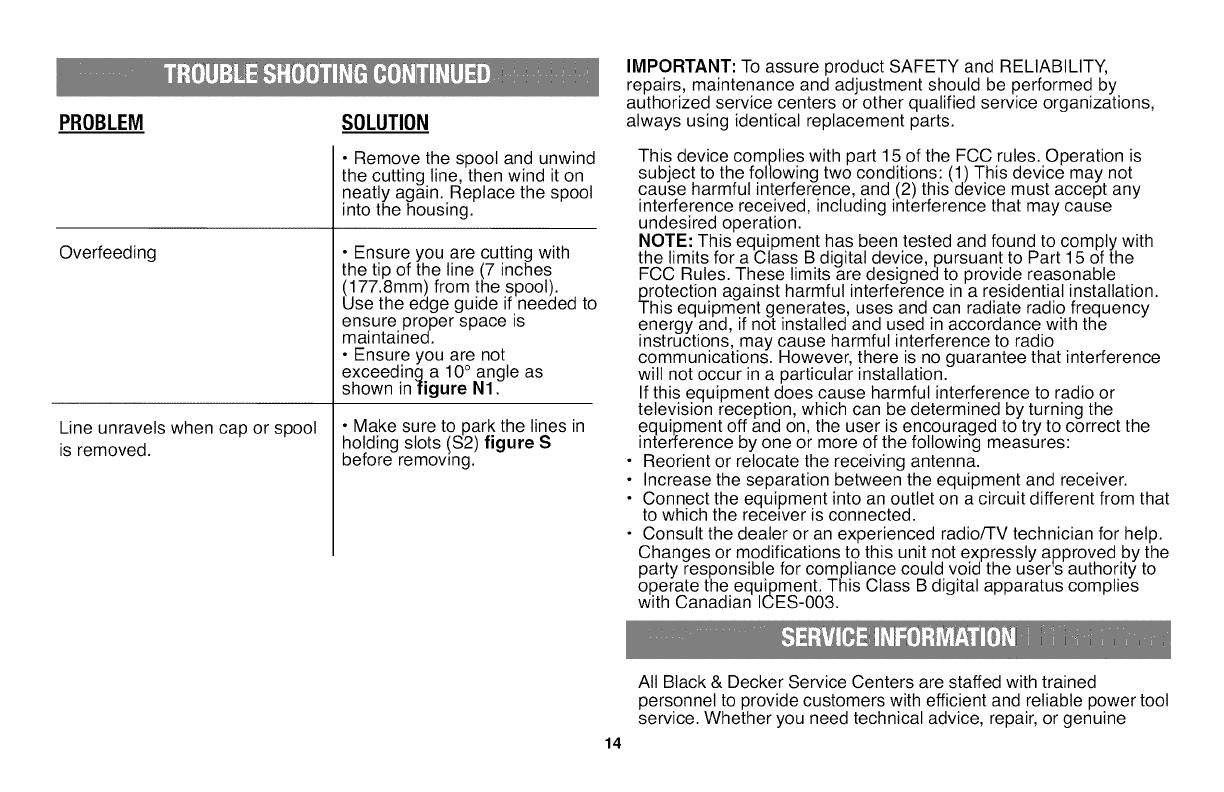
PROBLEM SOLUTION
Overfeeding
Line unravels when cap or spool
is removed.
• Remove the spool and unwind
the cutting line, then wind it on
neatly again. Replace the spool
into the housing.
• Ensure you are cutting with
the tip of the line (7 inches
(177.8mm) from the spool).
Use the edge guide if needed to
ensure proper space is
maintained.
• Ensure you are not
exceeding a 10° angle as
shown infigure N1.
• Make sure to park the lines in
holding slots (S2) figure S
before removing.
IMPORTANT: To assure product SAFETY and RELIABILITY,
repairs, maintenance and adjustment should be performed by
authorized service centers or other qualified service organizations,
always using identical replacement parts.
This device complies with part 15 of the FCC rules. Operation is
subject to the following two conditions: (1) This device may not
cause harmful interference, and (2) this device must accept any
interference received, including interference that may cause
undesired operation.
NOTE: This equipment has been tested and found to comply with
the limits for a Class B digital device, pursuant to Part 15 of the
FCC Rules. These limits are designed to provide reasonable
protection against harmful interference in a residential installation.
This equipment generates, uses and can radiate radio frequency
energy and, if not installed and used in accordance with the
instructions, may cause harmful interference to radio
communications. However, there is no guarantee that interference
will not occur in a particular installation.
If this equipment does cause harmful interference to radio or
television reception, which can be determined by turning the
equipment off and on, the user is encouraged to try to correct the
interference by one or more of the following measures:
Reorient or relocate the receiving antenna.
Increase the separation between the equipment and receiver.
Connect the equipment into an outlet on a circuit different from that
to which the recewer is connected.
Consult the dealer or an experienced radio/TV technician for help.
Changes or modifications to this unit not expressly approved by the
party responsible for compliance could void the user's authority to
operate the equipment. This Class B digital apparatus complies
with Canadian ICES-003.
14
All Black & Decker Service Centers are staffed with trained
personnel to provide customers with efficient and reliable power toot
service. Whether you need technical advice, repair, or genuine

factoryreplacementparts,contacttheBlack&Deckerlocation
nearestyou.Tofindyourlocalservicelocation,refertotheyellow
pagedirectoryunder"Tools--Electric"orcall:1-800-544-6986or
visitwww.blackanddecker.com
Black&Decker(U.S.)Inc.warrantsthisproductforthreeyears
againstanydefectsinmaterialorworkmanship.Thedefective
productwiltbereplacedorrepairedatnochargeineitheroftwo
ways:
Thefirst,whichwiltresultinexchangesonly,istoreturntheproduct
totheretailerfromwhomitwaspurchased(providedthatthestoreis
aparticipatingretailer).Returnsshouldbemadewithinthetime
periodoftheretailer'spolicyforexchanges(usually30to90days
afterthesale).Proofofpurchasemayberequired.Pleasecheck
withtheretailerfortheirspecificreturnpolicyregardingreturnsthat
arebeyondthetimesetforexchanges.
Thesecondoptionistotakeorsendtheproduct(prepaid)toaBlack
&DeckerownedorauthorizedServiceCenterforrepairor
replacementatouroption.Proofofpurchasemayberequired.Black
&Deckerownedandauthorizedservicecentersarelistedunder
"Tools-Electric"intheyellowpagesofthephonedirectory.
Thiswarrantydoesnotapplytoaccessories.Thiswarrantygivesyou
specificlegalrightsandyoumayhaveotherrightswhichvaryfrom
statetostate.Shouldyouhaveanyquestions,contactthemanager
ofyournearestBlack&DeckerServiceCenter.Thisproductisnot
intendedforcommercialuse.
LATINAMERICA:Thiswarrantydoesnotapplytoproductssoldin
LatinAmerica.ForproductssoldinLatinAmerica,checkcountry
specificwarrantyinformationcontainedinthepackaging,callthe
localcompanyorseethewebsiteforwarrantyinformation.
FREEWARNINGLABELREPLACEMENT:Ifyourwarninglabels
becomeillegibleoraremissing,call1-800-544-6986forafree
replacement.
15
Imported by
Black & Decker (U.S.) Inc.,
701 E. Joppa Rd.
Towson, MD 21286 U.S.A.
See 'Tools-Electric'
-Yellow Pages -
for Service & Sales
PARA OTRAS LOCALIDADES LLAME AL 01 800 847 2309 o 01 800 847 2312.
BLACK & DECKER S.A. DE C.V.
BOSQUES DE CIDROS ACCESO RADIATAS NO. 42
COL. BOSQUES DE LAS LOMAS.
05120 MEXICO, D.F
TEL. (01 55) 5326 7100
01 800 847 2309/01 800 847 2312
Vea "Herramientas
el_ctricas (Tools-Electric)" SE_¢N
AMARIL_
- P_ginas amarillas .... _,_'_,o
para Servicio y ventas
Cat. No. LST136
Copyright @2012 Black & Decker
Form No. 90578591 rev02
48
March 2012
Printed inChina
/