Page is loading ...

User’s Guide
Mic/Line Mixer and Volume Controller
68-793-01 Rev. C
02 09
MVC 121

Precautions
This symbol is intended to alert the user of
important operating and maintenance (servicing)
instructions in the literature provided with the
equipment.
This symbol is intended to alert the user of the
presence of uninsulated dangerous voltage within
the product's enclosure that may present a risk of
electric shock.
Caution
Read Instructions • Read and understand all safety and operating instructions
before using the equipment.
Retain Instructions • The safety instructions should be kept for future
reference.
Follow Warnings • Follow all warnings and instructions marked on the
equipment or in the user information.
Avoid Attachments • Do not use tools or attachments that are not
recommended by the equipment manufacturer because they may be
hazardous.
Warning
Power sources • This equipment should be operated only from the power source
indicated on the product. This equipment is intended to be used with a main
power system with a grounded (neutral) conductor. The third (grounding) pin is
a safety feature, do not attempt to bypass or disable it.
Power disconnection • To remove power from the equipment safely, remove all
power cords from the rear of the equipment, or the desktop power module (if
detachable), or from the power source receptacle (wall plug).
Power cord protection • Power cords should be routed so that they are not likely to
be stepped on or pinched by items placed upon or against them.
Servicing • Refer all servicing to qualified service personnel. There are no user-
serviceable parts inside. To prevent the risk of shock, do not attempt to service
this equipment yourself because opening or removing covers may expose you to
dangerous voltage or other hazards.
Slots and openings • If the equipment has slots or holes in the enclosure, these are
provided to prevent overheating of sensitive components inside. These openings
must never be blocked by other objects.
Lithium battery • There is a danger of explosion if battery is incorrectly replaced.
Replace it only with the same or equivalent type recommended by the
manufacturer. Dispose of used batteries according to the manufacturer's
instructions.
Ce symbole sert à avertir l’utilisateur que la
documentation fournie avec le matériel contient
des instructions importantes concernant
l’exploitation et la maintenance (réparation).
Ce symbole sert à avertir l’utilisateur de la présence
dans le boîtier de l’appareil de tensions
dangereuses non isolées posant des risques
d’électrocution.
Attention
Lire les instructions• Prendre connaissance de toutes les consignes de sécurité et
d’exploitation avant d’utiliser le matériel.
Conserver les instructions• Ranger les consignes de sécurité afin de pouvoir les
consulter à l’avenir.
Respecter les avertissements • Observer tous les avertissements et consignes
marqués sur le matériel ou présentés dans la documentation utilisateur.
Eviter les pièces de fixation • Ne pas utiliser de pièces de fixation ni d’outils
non recommandés par le fabricant du matériel car cela risquerait de poser
certains dangers.
Avertissement
Alimentations• Ne faire fonctionner ce matériel qu’avec la source d’alimentation indiquée
sur l’appareil. Ce matériel doit être utilisé avec une alimentation principale comportant
un fil de terre (neutre). Le troisième contact (de mise à la terre) constitue un dispositif de
sécurité : n’essayez pas de la contourner ni de la désactiver.
Déconnexion de l’alimentation• Pour mettre le matériel hors tension sans danger,
déconnectez tous les cordons d’alimentation de l’arrière de l’appareil ou du
module d’alimentation de bureau (s’il est amovible) ou encore de la prise secteur.
Protection du cordon d’alimentation • Acheminer les cordons d’alimentation de
manière à ce que personne ne risque de marcher dessus et à ce qu’ils ne soient
pas écrasés ou pincés par des objets.
Réparation-maintenance • Faire exécuter toutes les interventions de réparation-
maintenance par un technicien qualifié. Aucun des éléments internes ne peut être
réparé par l’utilisateur. Afin d’éviter tout danger d’électrocution, l’utilisateur ne
doit pas essayer de procéder lui-même à ces opérations car l’ouverture ou le
retrait des couvercles risquent de l’exposer à de hautes tensions et autres dangers.
Fentes et orifices • Si le boîtier de l’appareil comporte des fentes ou des orifices,
ceux-ci servent à empêcher les composants internes sensibles de surchauffer. Ces
ouvertures ne doivent jamais être bloquées par des objets.
Lithium Batterie • Il a danger d'explosion s'll y a remplacment incorrect de la
batterie. Remplacer uniquement avec une batterie du meme type ou d'un ype
equivalent recommande par le constructeur. Mettre au reut les batteries usagees
conformement aux instructions du fabricant.
Safety Instructions • English
Consignes de Sécurité • Français
Sicherheitsanleitungen • Deutsch
Dieses Symbol soll dem Benutzer in der im
Lieferumfang enthaltenen Dokumentation
besonders wichtige Hinweise zur Bedienung und
Wartung (Instandhaltung) geben.
Dieses Symbol soll den Benutzer darauf
aufmerksam machen, daß im Inneren des
Gehäuses dieses Produktes gefährliche
Spannungen, die nicht isoliert sind und die einen
elektrischen Schock verursachen können,
herrschen.
Achtung
Lesen der Anleitungen • Bevor Sie das Gerät zum ersten Mal verwenden,
sollten Sie alle Sicherheits-und Bedienungsanleitungen genau durchlesen und
verstehen.
Aufbewahren der Anleitungen • Die Hinweise zur elektrischen Sicherheit des
Produktes sollten Sie aufbewahren, damit Sie im Bedarfsfall darauf
zurückgreifen können.
Befolgen der Warnhinweise • Befolgen Sie alle Warnhinweise und Anleitungen
auf dem Gerät oder in der Benutzerdokumentation.
Keine Zusatzgeräte • Verwenden Sie keine Werkzeuge oder Zusatzgeräte, die
nicht ausdrücklich vom Hersteller empfohlen wurden, da diese eine
Gefahrenquelle darstellen können.
Vorsicht
Stromquellen • Dieses Gerät sollte nur über die auf dem Produkt angegebene
Stromquelle betrieben werden. Dieses Gerät wurde für eine Verwendung mit
einer Hauptstromleitung mit einem geerdeten (neutralen) Leiter konzipiert. Der
dritte Kontakt ist für einen Erdanschluß, und stellt eine Sicherheitsfunktion dar.
Diese sollte nicht umgangen oder außer Betrieb gesetzt werden.
Stromunterbrechung • Um das Gerät auf sichere Weise vom Netz zu trennen,
sollten Sie alle Netzkabel aus der Rückseite des Gerätes, aus der externen
Stomversorgung (falls dies möglich ist) oder aus der Wandsteckdose ziehen.
Schutz des Netzkabels • Netzkabel sollten stets so verlegt werden, daß sie nicht
im Weg liegen und niemand darauf treten kann oder Objekte darauf- oder
unmittelbar dagegengestellt werden können.
Wartung • Alle Wartungsmaßnahmen sollten nur von qualifiziertem
Servicepersonal durchgeführt werden. Die internen Komponenten des Gerätes
sind wartungsfrei. Zur Vermeidung eines elektrischen Schocks versuchen Sie in
keinem Fall, dieses Gerät selbst öffnen, da beim Entfernen der Abdeckungen die
Gefahr eines elektrischen Schlags und/oder andere Gefahren bestehen.
Schlitze und Öffnungen • Wenn das Gerät Schlitze oder Löcher im Gehäuse
aufweist, dienen diese zur Vermeidung einer Überhitzung der empfindlichen
Teile im Inneren. Diese Öffnungen dürfen niemals von anderen Objekten
blockiert werden.
Litium-Batterie • Explosionsgefahr, falls die Batterie nicht richtig ersetzt wird.
Ersetzen Sie verbrauchte Batterien nur durch den gleichen oder einen
vergleichbaren Batterietyp, der auch vom Hersteller empfohlen wird. Entsorgen
Sie verbrauchte Batterien bitte gemäß den Herstelleranweisungen.
Este símbolo se utiliza para advertir al usuario
sobre instrucciones importantes de operación y
mantenimiento (o cambio de partes) que se desean
destacar en el contenido de la documentación
suministrada con los equipos.
Este símbolo se utiliza para advertir al usuario
sobre la presencia de elementos con voltaje
peligroso sin protección aislante, que puedan
encontrarse dentro de la caja o alojamiento del
producto, y que puedan representar riesgo de
electrocución.
Precaucion
Leer las instrucciones • Leer y analizar todas las instrucciones de operación y
seguridad, antes de usar el equipo.
Conservar las instrucciones • Conservar las instrucciones de seguridad para
futura consulta.
Obedecer las advertencias • Todas las advertencias e instrucciones marcadas
en el equipo o en la documentación del usuario, deben ser obedecidas.
Evitar el uso de accesorios • No usar herramientas o accesorios que no sean
especificamente recomendados por el fabricante, ya que podrian implicar
riesgos.
Advertencia
Alimentación eléctrica • Este equipo debe conectarse únicamente a la fuente/tipo de
alimentación eléctrica indicada en el mismo. La alimentación eléctrica de este equipo debe
provenir de un sistema de distribución general con conductor neutro a tierra. La tercera
pata (puesta a tierra) es una medida de seguridad, no puentearia ni eliminaria.
Desconexión de alimentación eléctrica • Para desconectar con seguridad la acometida
de alimentación eléctrica al equipo, desenchufar todos los cables de alimentación en el
panel trasero del equipo, o desenchufar el módulo de alimentación (si fuera
independiente), o desenchufar el cable del receptáculo de la pared.
Protección del cables de alimentación • Los cables de alimentación eléctrica se deben
instalar en lugares donde no sean pisados ni apretados por objetos que se puedan
apoyar sobre ellos.
Reparaciones/mantenimiento • Solicitar siempre los servicios técnicos de personal
calificado. En el interior no hay partes a las que el usuario deba acceder. Para
evitar riesgo de electrocución, no intentar personalmente la reparación/
mantenimiento de este equipo, ya que al abrir o extraer las tapas puede quedar
expuesto a voltajes peligrosos u otros riesgos.
Ranuras y aberturas • Si el equipo posee ranuras o orificios en su caja/alojamiento,
es para evitar el sobrecalientamiento de componentes internos sensibles. Estas
aberturas nunca se deben obstruir con otros objetos.
Batería de litio • Existe riesgo de explosión si esta batería se coloca en la posición
incorrecta. Cambiar esta batería únicamente con el mismo tipo (o su equivalente)
recomendado por el fabricante. Desachar las baterías usadas siguiendo las
instrucciones del fabricante.
Instrucciones de seguridad • Español

i
ᅝܼ乏ⶹ•Ё᭛
䖭Ͼヺোᦤ⼎⫼᠋䆹䆒⫼᠋ݠЁ
᳝䞡㽕ⱘ᪡㓈ᡸ䇈ᯢDŽ
䖭Ͼヺো䄺ਞ⫼᠋䆹䆒ᴎݙ᳝
䴆ⱘॅ䰽⬉य़ˈ᳝㾺⬉ॅ䰽DŽ
⊼ᛣ
䯙䇏䇈ᯢк• 䑩ㅸỀ䑩嬦嫿⡈⼆枼敆嬼䍇夤ㆁ㙊
⫊₩⏍Ề䑩嬵㕏ɿ
ֱᄬ䇈ᯢк• 䑩ㅸⷕ⪙⫊₩嬵㕏ᶧḦ⡈⭇㚦Ề䑩ɿ
䙉ᅜ䄺ਞ• 䑩ㅸⷕ徶⫉ᷨ␂⏍䑩ㅸ㉈⊘ᵋ䗅ㆁ㙊⫊₩
⏍㐎ẝ嬵㕏ɿ
䙓ܡ䗑ࡴ• ᵎ壂Ề䑩嬦ᷨ␂⋃⒇㯢㙊㋩劑䗅₸ㅗ弾
⇡嫿⡈澤Ḧ忀₎⊲斪ɿ
䄺ਞ
⬉⑤• 嬦嫿⡈⌫倾Ề䑩ᷨ␂ᵋ㝈㕏䗅䑶㷑ɿ嫿⡈⼆枼
Ề䑩㙊♱一䗅Ờ䑶䰼丠Ờ䑶ɿ䩭ᵊ㚢一澠♱一澡㕰
⫊₩嫿㓾澤ᵎ倾ᵎ䑩ㅗ崴弈ɿ
ᢨᥝ⬉⑤• ᵻ⫊₩♱ḏ嫿⡈㈕㋊䑶㷑澤嬸㈕㋊ㆁ㙊嫿
⡈⍏ㅗ㞍暣䑶㷑䗅䑶㷑一澤ㅗḼẖ㋦ⅱⵃ䑶䰼丠䗅
䑶㷑一ɿ
⬉⑤㒓ֱᡸ• ⣦Ⓟⵄ一澤忀₎埬嵪嵐澤ㅗ愎䆪㉥⋌ɿ
㓈ᡸ•ㆁ㙊丵Ἧ⼆枼䑲嫥嬂䗅丵Ἧ᷻⎙弜垍ɿ嫿⡈
怩㯢㙊䑩ㅸ⌰Ḧ㘵㊣䗅昷ḷɿᵻ忀₎℻䋱大䑶⊲斪
ᵎ壂儫ⴲ嬖☿㆔⹁嫿⡈䘗⪑丵Ἧ嬦嫿⡈ɿ
䗮亢ᄨ• 㙊ᷜ嫿⡈㙻⠴ᵋ㙊彛栏㤾ㅗ⪕澤⫄ḭ㕰䑩㚦
敳㪣㙻㒐だ₄ḷ弈䀮ɿᵎ壂䑩Ḽẖᵝ壀㉢Ẑ彛
栏⪕ɿ
䫖⬉∴• ᵎ㪤䞯䗅㘵㊣䑶㮡ṛ㙊䅇㿹䗅⊲斪ɿ⼆枼Ề䑩
ᵏ⋃⫷㋩劑䗅䘹⍍ㅗ䘹弒⛌⌸䗅䑶㮡ɿ㉊䂨䑠ᷨ⋃
䗅⸻嫯⡅䍇ⷠ⹄䑶㮡ɿ
FCC Class A Notice
This equipment has been tested and found to comply with the limits for a
Class A digital device, pursuant to part 15 of the FCC Rules. These limits are
designed to provide reasonable protection against harmful interference when the
equipment is operated in a commercial environment. This equipment generates,
uses and can radiate radio frequency energy and, if not installed and used in
accordance with the instruction manual, may cause harmful interference to radio
communications. Operation of this equipment in a residential area is likely to
cause harmful interference, in which case the user will be required to correct the
interference at his own expense.
N This unit was tested with shielded cables on the peripheral devices. Shielded
cables must be used with the unit to ensure compliance.


MVC 121 • Quick Start Guide
Quick Start Guide — MVC 121
QS-1
Step 1
Disconnect all power prior to installing the MVC 121.
Step 2
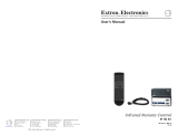
Mount the MVC (if applicable) or affix the rubber feet to the bottom
of the MVC for tabletop use. The MVC can be mounted in a rack
shelf, under furniture, or to a projector mount. See chapter 2,
“Installation and Operation”, for details.
M
IX
E
R
/
V
O
L
U
M
E
C
O
N
T
R
O
L
L
E
R
M
I
C
1
VOL
M
I
C
2
M
A
I
N
3
M
A
S
T
E
R
Under furniture
(2) 4-40 x 3/16" screws
Use 2 mounting holes
on opposite corners
VersaTools Rack Shelf
1/4 Rack Width
False Front Face Plate
D
I
S
T
R
I
B
U
T
I
O
N
A
M
P
L
I
F
I
E
R
D
I
S
T
R
I
B
U
T
I
O
N
A
M
P
L
I
F
I
E
R
M
I
X
E
R
/
V
O
L
U
M
E
C
O
N
T
R
O
L
L
E
R
M
I
C
1
VOL
M
I
C
2
M
A
I
N
3
M
A
S
T
E
R
Rack shelf mounting
Projector
PMK 100
MVC 121
ON
INPUTS
O
U
T
P
U
T
S
L
E
V
E
L
4
8
V
ON
OFF
MAIN 3
LINE
MIC
RS-232
MUTE
TxRx
POWER
12V
0.5A MAX
L
1
2
R
3
1
2
3
4
1
2
1
2
MIXER/VOLUME
CONTROLLER
FIXED
L
R
MIC 1
MIC 2
VARIABLE
L
R
Mounting
Bolt
To a projector mount

Quick Start Guide — MVC 121, cont’d
MVC 121 • Quick Start GuideQS-2
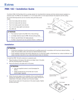
Step 3
Attach the cables and set the DIP switches.
MVC 121
ON
INPUTS
OUTPUTS
LEVEL
48V
ON
OFF
MAIN 3
LINE
MIC
RS-232
MUTE
Tx Rx
POWER
12V
0.5A MAX
L
1
2
R
3
1
2
3
4
1
2
1
2
MIXER/VOLUME
CONTROLLER
FIXED
L
R
MIC 1
MIC 2
VARIABLE
L
R
7 81 2 3 5
4 6
1
Power connector — Connect the 12 VDC external power
supply.
CAUTION
When connecting the power supply, voltage
polarity is extremely important. Applying power
with incorrect voltage polarity could damage the
power supply and the MVC 121.
2
Mic input DIP switch — Mic 1 and Mic 2 inputs are controlled
via the DIP switch.
1. Set the mic input Level according to the mic type:
a. Wireless mic: Set the mic’s DIP switch to Line (On).
b. Wired mic: Set the mic’s DIP switch to Mic (Off).
2. Set the 48V phantom power according to the mic type:
a. Condenser mic: Set the mic’s DIP switch to On.
b. Dynamic mic: Set the mic’s DIP switch to Off.
CAUTION
Never set a dynamic microphone to 48V, doing so
may damage the microphone. For condenser mics,
verify that the mic will safely operate at 48VDC.
When the DIP switch is set to line level, 48V phantom
power is disabled regardless of its DIP switch position.
3
Mic 1 and Mic 2 input connector — Up to two mono
microphones, balanced and/or unbalanced, may be connected.
4
Main 3 line level input connector — Connect a line level audio
source.

MVC 121 • Quick Start Guide
5
Variable output connector — The balanced/unbalanced stereo
output is controlled by the Master volume control knob on the
front panel.
6
Fixed output connector — The balanced/unbalanced stereo
output is set at a fixed level for input to a recording device.
Signal level can be adjusted at the recording device.
7
RS-232 connector — Connect an RS-232 device (control system
or PC) for two-way RS-232 communication.
8
Mute connector — Connect a contact closure device to mute
the inputs. See “Contact Closure Mute” in chapter 3.
Step 4
Adjust the front panel volume controls. See chapter 2, “Installation
and Operation”.
MIXER/VOLUME CONTROLLER
MVC 121
MIC 1
VOL
MIC 2 MAIN 3 MASTER
2
1
3
4
5
1
1
Volume level LEDs — Mic 1, Mic 2, Main 3, and Master gain/
volume level indicators.
2
Mic 1 input gain control and on/off indication LED
3
Mic 2 input gain control and on/off indication LED
4
Main 3 line level input gain control and on/off indication LED
5
Master output volume control and on/off indication LED to
control variable output
QS-3

Quick Start Guide — MVC 121, cont’d
MVC 121 • Quick Start GuideQS-4

MVC 121 • Table of Contents
Chapter 1 • Introduction .......................................................... 1-1
About the MVC 121 ............................................................... 1-2
Features ...................................................................................... 1-2
Chapter 2 • Installation and Operation.......................... 2-1
Mounting the MVC 121 ....................................................... 2-2
Tabletop use ........................................................................... 2-2
UL rack mounting guidelines ................................................. 2-2
Rack mounting ....................................................................... 2-3
Furniture or projector mounting ........................................... 2-4
Furniture mounting .......................................................... 2-4
Projector mounting .......................................................... 2-5
Application Diagram ........................................................... 2-6
Rear Panel Features and Cabling .................................. 2-7
Front Panel Features .......................................................... 2-12
Turning channels on/off .......................................................2-13
On/off status LEDs ...............................................................2-14
Mute/unmute channel .........................................................2-14
Front panel security lockout (executive mode) ..................2-14
Chapter 3 • Remote Control ................................................... 3-1
RS-232 Programmer’s Guide ............................................ 3-2
Host-to-MVC communications ............................................... 3-2
MVC-initiated messages ........................................................ 3-2
Error responses ...................................................................... 3-2
Using the command/response table ..................................... 3-3
Command/response table ..................................................... 3-5
Windows-based Program Control .................................. 3-9
Installing the software ..........................................................3-9
Using the software ..............................................................3-10
Setting output volume range limits
................................ 3-10
Using the help system ......................................................... 3-12
Updating the firmware ....................................................... 3-12
Contact Closure Mute ........................................................3-13
Appendix A • Specifications, Part Numbers, and
Accessories........................................................................................ A-1
Specifications ......................................................................... A-2
Included Parts ......................................................................... A-5
Optional Accessories .......................................................... A-5
Table of Contents
TOC-i

MVC 121 • Table of Contents
Table of Contents, cont’d
TOC-ii
68-793-01 Rev. C
02 09
All trademarks mentioned in this manual are the properties of their respective owners.

MVC 121 Mic/Line Mixer
1
Chapter One
Introduction
About the MVC 121
Features

MVC 121 • Introduction
Introduction
About the MVC 121
The Extron MVC 121 is an audio mixer and volume controller in
the Extron VersaTools
™
product line that mixes up to two mic
inputs (mono, balanced/unbalanced) with one main line level
input (stereo, balanced/unbalanced). Each mic input and the
main line level input have their own gain control knobs, and the
mixed output also features a volume control knob.
Volume adjustment interval varies with the speed of knob
rotation, i.e., turning the knob slowly increments the volume in
smaller steps (0.5 dB), and turning the knob quickly increments
the volume in larger steps (2.5 dB).
Two sets of outputs include a fixed output that is independent
from volume control, and a variable output that is volume
adjustable. All inputs and outputs are via 3.5 mm captive screw
connectors, and the volume settings are indicated by four LEDs.
The MVC offers RS-232 control of input gain/attenuation, and
control of output volume. RS-232 control also includes the
capability to turn the inputs and output on/off. The latest
firmware can be uploaded using RS-232 and the Extron control
program for Windows
®
.
Features
Furniture, rack, and projector mountability — The Extron
MVC 121 can be mounted under a desk or other
furniture, or mounted on a projector lift with optional
brackets. Alternatively, it can be rack mounted on an
optional rack shelf.
Microphone inputs — Built-in switchable microphone amplifier
with 48 V phantom power and separate level setting for
each microphone.
Front panel security lockout (executive mode) — The volume
settings for the inputs and the output can be protected
from unauthorized changes by enabling the executive
mode, although the volume settings can still be displayed
by the LEDs when the volume control knobs are turned.
Stand-alone volume controller — The MVC 121 can operate as
a volume controller for the main line level input with
both mic inputs turned off.
RS-232 control — Allows remote control of the MVC using the
Extron Simple Instruction Set
™
(SIS
™
), the Extron control
software for Windows, or other remote control system.
1-2

MVC 121 Mic/Line Mixer
2
Chapter Two
Installation and Operation
Mounting the MVC 121
Application Diagram
Rear Panel Features and Cabling
Front Panel Features

MVC 121 • Installation and Operation
Installation and Operation
Mounting the MVC 121
The one rack unit high, quarter rack wide MVC can be set on a
table, mounted on a rack shelf, mounted under a desk or
tabletop, or mounted on a projector bracket.
Tabletop use
Each MVC comes with rubber feet (not installed). For tabletop
use, attach a self-adhesive rubber foot to each corner of the
bottom of the unit.
UL rack mounting guidelines
The following Underwriters Laboratories (UL) guidelines
pertain to the safe installation of the MVC 121 in a rack.
1. Elevated operating ambient temperature — If installed in
a closed or multi-unit rack assembly, the operating
ambient temperature of the rack environment may be
greater than room ambient temperature. Therefore,
install the MVC in an environment compatible with the
maximum ambient temperature (Tma = +122 °F, +50 °C)
specified by Extron.
2. Reduced air flow — Install the equipment in a rack so that
the amount of air flow required for safe operation of the
equipment is not compromised.
3. Mechanical loading — Mount the equipment in the rack
so that a hazardous condition is not achieved due to
uneven mechanical loading.
4. Circuit overloading — Connect the equipment to the
supply circuit and consider the effect that circuit
overloading might have on overcurrent protection and
supply wiring. Appropriate consideration of equipment
nameplate ratings should be used when addressing this
concern.
5. Reliable earthing (grounding) — Maintain reliable
grounding of rack-mounted equipment. Pay particular
attention to supply connections other than direct
connections to the branch circuit (e.g. use of power strips).
2-2

MVC 121 • Installation and Operation
Rack mounting
For optional rack mounting, do not install the rubber feet.
Mount the MVC on a VersaTools
®
19" 1U rack shelf (Extron
RSF 123, part #60-190-20; Extron RSB 123, part #60-604-20), or a
standard Universal 1U or Basic rack shelf (Extron RSU 129, part
#60-190-01; Extron RSB 129 or #60-604-01). On the standard rack
shelf, the MVC mounts in one of four locations to the rear of the
rack or in one of four locations to the front of the rack.
1. If rubber feet were previously installed on the bottom of
the MVC, remove them.
2. Mount the MVC on the rack shelf, using two 4-40 x 3/16"
screws in opposite (diagonal) corners to secure the MVC
to the shelf.
(2) 4-40 x 3/16" screws
Use 2 mounting holes
on opposite corners
VersaTools Rack Shelf
1/4 Rack Width
False Front Face Plate
DISTRIBUTION AMPLIFIER
DISTRIBUTION AMPLIFIER
MIXER/VOLUME CO
NTROLLER
M
IC
1
VOL
M
IC
2
M
A
IN
3
M
A
S
T
E
R
Mounting the MVC on a VersaTools rack shelf
2-3

MVC 121 • Installation and Operation
Installation and Operation, cont’d
2-4
M
I
X
E
R
/
V
O
L
U
M
E
C
O
N
T
R
O
L
L
E
R
MIC
1
VOL
MIC 2
MA
IN 3
MASTER
D
I
S
T
R
I
B
U
T
I
O
N
A
M
P
L
I
F
I
E
R
M
D
A
S
E
R
IE
S
D
I
S
T
R
I
B
U
T
I
O
N
A
M
P
L
I
F
I
E
R
A
/
V S
W
IT
C
HE
R
A
U
T
O
S
W
I
C
H
M
O
D
E
N
O
R
M
A
L
A
U
T
O
1
2
3
4
Mounting the MVC on a standard 1U rack shelf
3. Install blank panel(s) or other unit(s) on the rack shelf.
Furniture or projector mounting
Furniture mount or projector mount the MVC using the
optional mounting kit (Extron MBU 123, part #70-212-01,
furniture; or Extron PMK 100, part #70-217-01, projector) as
follows:
1. Attach the mounting brackets to the MVC with the
machine screws provided.
2. If feet were previously installed on the bottom of the
MVC, remove them.
Furniture mounting
3a. Hold the MVC with the attached brackets against the
underside of the table or other furniture. Mark the
location of the screw holes of the bracket on the mounting
surface.
4a. Drill 3/32" (2 mm) diameter pilot holes, 1/4" (6.3 mm)
deep in the mounting surface at the marked screw
locations.
5a. Insert #8 wood screws into the four pilot holes. Tighten
each screw into the mounting surface until just less than
1/4" of the screw head protrudes.
6a. Align the mounting screws with the slots in the brackets
and place the MVC against the surface, with the screws
through the bracket slots. See the following illustration.

MVC 121 • Installation and Operation
M
I
X
E
R
/
V
O
L
U
M
E
C
O
N
T
R
O
L
L
E
R
M
IC
1
VOL
M
IC
2
M
A
IN
3
M
A
S
T
E
R
Mounting the MVC to furniture
7a. Slide the MVC slightly forward or back, then tighten all
four screws to secure the MVC in place.
Projector mounting
3b. Secure the MVC to a projector mount or other surface by
inserting the mounting bolt through the bracket’s slotted
hole, as shown below.
Projector
PMK 100
MVC 121
ON
INPUTS
O
U
T
P
U
T
S
L
E
V
E
L
4
8
V
ON
OFF
MAIN 3
LINE
MIC
RS-232
MUTE
TxRx
POWER
12V
0.5A MAX
L
1
2
R
3
1
2
3
4
1
2
1
2
MIXER/VOLUME
CONTROLLER
FIXED
L
R
MIC 1
MIC 2
VARIABLE
L
R
Mounting
Bolt
Mounting the MVC to a projector mount
2-5

MVC 121 • Installation and Operation
Installation and Operation, cont’d
2-6
Application Diagram
MVC 121
O
N
I
N
P
U
T
S
OUTPUTS
LEVEL
48V
O
N
O
F
F
M
A
I
N
3
L
I
N
E
M
I
C
R
S
-
2
3
2
M
U
T
E
T
x
R
x
P
O
W
E
R
12V
0.5A
MA
X
L
1
2
R
3
1
2
3
4
1
2
1
2
M
IXER/VO
LUM
E
CO
NTR
OLLER
F
I
X
E
D
L
R
M
IC
1
M
IC
2
V
A
R
IA
B
L
E
L
R
Extron
SW 6AV
Switcher
Extron
MVC 121
Mixer/Volume
Controller
10
0
-2
4
0
V
0
.
3
A
5
0
-6
0
H
z
R
E
M
O
T
E
L
R
L
R
L
R
L
R
L
R
LR
L
R
L
R
IN
P
U
T
S
OU
T
PU
T
S
5
2
1
3
4
A
6
B
S
W
6
A
V
IN
P
U
T
S
O
U
T
P
U
T
S
S
YN
C
IN
1
2
3
4
5
6
A
B
OUT
L
IS
T
E
D
1
T
2
3
I
.T
.
E
.
C
U
S
Audio Amplifier
Audio Recorder
RS-232 Control
Wireless
Microphone
Contact Closure
Mute (AAP)

MVC 121 • Installation and Operation
Rear Panel Features and Cabling
MVC 121
ON
INPUTS
OUTPUTS
LEVEL
48V
ON
OFF
MAIN 3
LINE
MIC
RS-232
MUTE
Tx Rx
POWER
12V
0.5A MAX
L
1
2
R
3
1
2
3
4
1
2
1
2
MIXER/VOLUME
CONTROLLER
FIXED
L
R
MIC 1
MIC 2
VARIABLE
L
R
7 81 2 3 5
4 6
1
Power connector — Connect the included 12 VDC external
power supply into the 2-pole 3.5 mm captive screw connector.
Be careful to observe the correct polarity.
Orange Captive Screw
Connector
Tie Wrap
Power Supply
Output Cord
Ridges
Smooth
AA
SECTION A–A
CAUTION
When connecting the power supply, voltage
polarity is extremely important. Applying power
with incorrect voltage polarity could damage the
power supply and the MVC 121. Identify the
power cord negative (ground) lead by the ridges on
the side of the cord or a black heat shrink wrapping
around it.
The two power cord wires must be kept separate
while the power supply is plugged in. Remove
power before wiring.
To verify the polarity before connection, check the no load
power supply output with a voltmeter.
CAUTION
The length of the exposed (stripped) copper wires is
important. The ideal length is 5/16” (7 mm).
Longer bare wires can short together. Shorter
wires are not as secure in the direct insertion
connectors and could be pulled out.
2-7

MVC 121 • Installation and Operation
Installation and Operation, cont’d
2-8
Use the supplied tie-wrap to strap the power cord to the
extended tail of the connector.
Your MVC 121 may have shipped with a blue captive
screw connector. This blue connector can be plugged
into either a blue or an orange power receptacle.
The ideal length of exposed (stripped) copper wire
for the blue connector is 3/16" (5 mm).
The blue connector does not have the extended tail or the
included tie-wrap.
Do not tin the power supply leads before installing in the
direct insertion connector. Tinned wires are not as
secure in the connectors and could be pulled out.
After making any adjustments to the MVC 121, either
via the front panel controls, SIS commands, or the
Extron Audio Products Control Program, wait at least
10 seconds after making those changes before
disconnecting power to the MVC 121. Failure to
observe the 10-second timeout may result in those
adjustments not being saved.
2
Mic input DIP switch— Mic 1 and Mic 2 inputs are controlled
via a DIP switch.
1. Set the mic input Level according to the microphone type:
a. Wireless mic: Set the mic’s DIP
switch to the Line position (On).
b. Wired mic: Set the mic’s DIP switch
to the Mic position (Off).
2. Set the 48V phantom power position according to
microphone type:
a. Condenser mic: Set the mic’s DIP switch to the On
position.
b. Dynamic mic: Set the mic’s DIP switch to the Off
position.
Condenser microphones require power. Dynamic
microphones do not require power.
When a mic’s input level DIP switch is set to “line”
level, that input’s 48V phantom power is disabled
regardless of the “48V” phantom power DIP switch
setting of that input.
ON
LEVEL
48V
ON
OFF
LINE
MIC
1
2
3
4
1
2
1
2
/