Gigabyte Poseidon User manual

Category
Computer cases
Type
User manual

This manual is also suitable for

20070301-GZXA1CA-STBSTS
rev. 1002
Poseidon
GZ-XA1CA-STB
GZ-XA1CA-STS
User’s Manual
The following are not covered by the warranty
1. Incorrect use or use of the product for any purpose other than its intended use.
2. Nonobservance of the proper operation provided. (e.g. over-clocking)
3. Malfunction due to interference from other devices.
4. Unauthorized modifi cation of the product.
5. Consequential damage to other objects due to the product’s fault.
6. Malfunction arising from casualties (earthquake, thunder, fi re, or fl ood).
7. The warranty label of the product has been removed or damaged.
8. The devices inside, including power supply, hard disk, CD-ROM drive, motherboard,
ventilator, etc, are not detached from the casing prior to the transportation of the computer
product, resulting in damage to the chassis or computer-related devices.
9. Any loss arising from nonobservance of the proper operation provided is not covered by the
warranty.
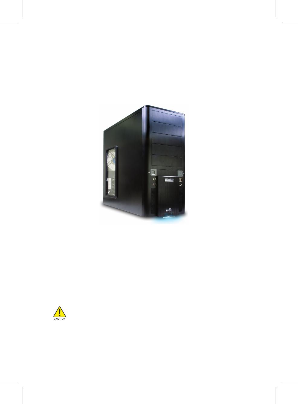
Poseidon Introduction
The chassis of Gigabyte Poseidon series is made by high-end Aluminum bezel design with dual 12cm
(front and rear) silent fans to offer the best ventilation for the system. The internal cable management
and tool-free design provide users with easer installation procedures and computer system
management. Using the patent 2 colors front projector light with changeable LED colors (blue/white)
and the see-through/air inlet side panel, users can customize their own style. For further information
and specifi cations of the Poseidon series, please download them from Gigabyte’s website.
Caution
Failure to wear gloves during installation of computer products may cause damage to personnel
and devices. Incorrect connector installation may possibly burn out the motherboard and other
components. Be sure to observe the instructions on installation in the manual.
Contents
1 Components Introduction ..................................................................................................... 4
1-1 Chassis’s Internal Structure ............................................................................. 4
1-2 Side Panel Introduction .................................................................................... 6
1-3 Front and Rear Panel Instruction ..................................................................... 7
2 Features .................................................................................................................................. 8
3 Specifi cation .......................................................................................................................... 8
4 Installation Instruction .......................................................................................................... 9
4-1 Installation of Power Supply ............................................................................. 9
4-2 Installation of Motherboard ............................................................................... 9
4-3 Installation of Interface Card .......................................................................... 10
4-4 Installation of Front I/O Panel ......................................................................... 11
4-5 Chassis’s Internal Structure ........................................................................... 12
4-6 Installation of 5.25” Front Device Bay ............................................................ 13
4-7 Installation of 3.5” Front Device Bay .............................................................. 13
4-8 Installation of Built-in HDD (Hard Disc Drive) ................................................. 14
4-9 Power cable installation of the front projector light ......................................... 14
4-10 DIY Front Bracket of Projector Light .............................................................. 15
4-11 Foot Stand Instruction .................................................................................... 16
4-12 Liquid Cooling System Support ...................................................................... 17
4-13 Recommended Air Cooling ............................................................................ 17
4
EnglishEnglishEnglishEnglishDeutschDeutschEnglish
PCI tool-free fastener
Motherboard/panel card
Power supply
1
1
Components Introduction
1-1 Chassis’s Internal Structure
3
6
7
2
8
4
5
1
3
2
4
5.25” Front device bay
5
EnglishDeutschDeutschEnglishEnglishEnglishEnglish
Build-in hard disk
Accessory box
Front cable kit
8
3.5” Floppy
(Refer to the right fi gures for the
attachments in the tool enclosure)
b. HD AUDIO
a.USB 2.0
c.IEEE1394
a. Standoff x 9
b. Securing runner x 6
c. Motherboard secur-
ing screw x 9
d. Wire clamp x 1
e. Power supply
securing screw x 4
f. Magnet ring x 1
e. Power supply of
front and rear fans
f. Basic chassis power
switch control cable
kit
(Refer to the right fi gures for the
cable connectors)
5
6
7
g. DIY transparent projector panel x 1
(Equipped with Poseidon at shipment)
d. Power supply of the
front projector light
6
EnglishEnglishEnglishEnglishDeutschDeutschEnglish
1-2 Side Panel Introduction
See-through side panel installation
complete fi gure (A-1)
(Factory default: vent side panel)
1-2-1 To replace the See-through side panel:
Step 1: Release 4 screws at the rear of the side panel to
remove the panel.
Step 2: Remove the factory default perforated side panel.
Step 3: Draw out the perforated side panel.
Step 4: Place and screw the See-through side panel properly
to complete the installation procedure.
7
EnglishDeutschDeutschEnglishEnglishEnglishEnglish
1-3-1 To remove front panel:
Step 1: Remove the left and right side panels ( see Step 1-2-1 on Page 6) and slightly pull out
both sides of the upper (see, Figure a) and lower (see Figure b) fasteners (see Figure c).
Figure a
Figure c
Rear panel (C)
Drainage outlet(C-2)
Rear fan (C-1)
1-3 Front and Rear Panel Instruction
Front panel (B)
Front panel (B-1)
Front fan (B-2)
Figure b
8
EnglishEnglishEnglishEnglishDeutschDeutschEnglish
2
Features
- High quality design -
(Patent Pending)Customizable light beam
projector w/ changeable LED color (Blue/White)
Hign-end Aluminum bezel design
Skidproof & shockproof foot stand
- Complete support -
Front bezel I/O (USBx2,IEEE1394x1, HD
audiox1)
Dual 12cm silent & shockproof fan
(Rear fan w/ LED)
Supports water cooling systems
- Integration of cooling technology -
(Patent pending)Integrated side panel
(See-through & elegant vent design)
Quad-ways front air-inlet design
- Convenience of assembly -
Internal Cable Management - provide users clean
assembly environment
Tool-less design & Hassle-Free Assembly
3
Specifi cation
Model : GZ-XA1CA-STB/GZ-XA1CA-STS
Case Type : Mid-Tower
Dimension : 200 x 440 x 495mm (W x H x D)
Front bezel Material : Aluminum
Color : Silver / Black
Side Panel : Elegant Vent Design
Body Material : SECC
Net Weight : 8 kg
5.25" drive bay (External) : 5
3.5" drive bay (External) : 1
3.5" drive bay (Internal) : 3
Expansion Slot : 7
Compatible MB : ATX / Micro ATX
System Fan (front) : 120 mm silent fan x1
System Fan (rear) : 120 mm silent fan w/ blue LEDs x1
I / O Ports : USB2.0 x2 / IEEE 1394 x1 / HD audio x1 set
Optional Thermal Solutions :
GIGABYTE Liquid Cooling - 3D Galaxy Series
GIGABYTE Air Cooling - G-Power Lite Series
- 3D Rocket Series
9
EnglishDeutschDeutschEnglishEnglishEnglishEnglish
Please follow the reference sections for installation.
To facilitate the installation, it is recommended to place the Poseidon chassis upright on the table.
Required tool: Power supply securing screw x 4.
4-1-1 Please remove the left side panel before placing the
power supply into the chassis.
4-1-2 Use screws to secure the power supply from the rear
side.
4-2 Installation of Motherboard
The
Poseidon
is compatible with the ATX/Micro ATX motherboard. Please confi rm the dimension
and specifi cations of the motherboard before installation.
Required tool: motherboard standoffs x 9 and securing screws x 9
4
Installation Instruction
4-1 Installation of Power Supply
4-2-1 According to motherboard specifi cations, select proper
screw holes, engage the standoffs into the correspond-
ing holes of the chassis.
4-2-2 Secure the motherboard with securing screws.
Motherboard Code Motherboard securing screw Standoffs
ATX A1-A9 9 9
MINI ATX M1-M9 9 9
MICRO ATX U1-U9 9 9
FLEX ATX F1-F6 6 6
Select proper rear I/O panel of the motherboard (typically supplied by motherboard manu-
factures).
10
EnglishEnglishEnglishEnglishDeutschDeutschEnglish
The
Poseidon
supports tool-free installation of interface cards, e.g. Graphic card and Network
Card, etc.
Required tool: None
4-3-1 Unlock securing fasteners of the PCI socket; push
the fastener downwards fi rst.
4-3-3 Remove the internally attached dust-proof PCI cover.
4-3-4 Insert the interface card into the expansion slot with
care.
Make sure all interface cards are fully seated in the corresponding slots.
4-3 Installation of Interface Card
4-3-2 And then, push the fastener upwards.
11
EnglishDeutschDeutschEnglishEnglishEnglishEnglish
The front panel consists of (1) Two USB 2.0 ports, one IEEE 1394, and one High Defi nition
Audio connector.
(2) Basic chassis power switch control cable kit
Required tool: None
(1) Two USB 2.0 ports, one IEEE 1394, and one High Defi nition Audio connector.
4-4-1 Insert the USB2.0 connector into the corresponding socket on the motherboard.
USB 2.0 Connector
Pin Defi nition Pin Defi nition
1 Power 6 USB Dy+
2 Power 7 GND
3 USB Dx- 8 GND
4 USB Dy- 9
5 USB Dx+ 10 USB Over Current
4-4-2 Insert the IEEE 1394 connector into the corresponding socket on the motherboard.
4-4 Installation of Front I/O Panel
Please refer to the instructions supplied by the motherboard manufacturer and make
sure the correct type of connector prior to installation.
Incorrect connector installation may possibly burn out the motherboard and other
components. Be sure to observe the instructions on installation in the manual. Any
loss arising from nonobservance of the proper operation provided is not covered by
the warranty.
Different motherboards may have different installation positions. For detailed
instructions, please refer to the instructions supplied by the motherboard manufacturer.
a. IEEE1394 Connector A
Pin Defi nition Pin Defi nition
1 TPA+ 6 TPB-
2TPA-7
3 GND 8 +12V
4 GND 9 +12V
5 TPB+ 10 GND
b. IEEE1394 Connector B
Pin Defi nition Pin Defi nition
1 TPA+ 6 TPB-
2 TPA- 7 +12V
3 GND 8 +12V
4 GND 9
5 TPB+ 10 GND
c. IEEE1394 Connector C
Pin Defi nition Pin Defi nition
1 +12V 9 +12V
2 +12V 10 +12V
3 TPA+ 11 TPA1+
4 TPA- 12 TPA1-
5 GND 13 GND
6 GND 14
7 TPB+ 15 TPB1+
8 TPB- 16 TPB1-
12
EnglishEnglishEnglishEnglishDeutschDeutschEnglish
4-4-3 Attach the HD Audio connector to the pin located on the motherboard.
Pin Defi nition
1 MIC2_L
2 GND
3 MIC2_R
4 -ACZ_DET
5 Line2_R
6 FSENSE1
7 FAUDIO_JD
8 No Pin
9 LINE2_L
10 FSENSE2
Pin Defi nition Pin Defi nition
1 MIC 6 NC
2 GND 7 NC
3 MIC Power 8 NO Pin
4 NC 9 Line Out (L)
5 Line Out (R) 10 NC
(2) Basic chassis power switch control cable kit.
Follow the connectors listed below for installation (see the fi gure below).
Connector Color
Speaker Yellow(+) / Black(-)
Reset SW Blue(+) / White(-)
Power SW Orange(+) / White(-)
POW LED+ Green
POW LED- White
H.D.D. LED Red(+) / White(-)
The Poseidonis equipped with dual 12cm silent fans (front and rear).
Required tool: None
4-5-1 Plug the front fan 3-pin power connector into the fan
power connector of the motherboard system.
4-5 Chassis’s Internal Structure
Be sure to remember that different motherboards may have different installation
positions. For detailed instructions, please refer to the instructions supplied by the
motherboard manufacturer.
13
EnglishDeutschDeutschEnglishEnglishEnglishEnglish
The installation of 5.25” CD-ROM is also intended for installation of general 5.25” front device bay.
Required tool: None
4-6-1 Remove the front panel (see Step 1-3-1
on Page 7) and take off the 5.25” internal
metallic panel.
4-6-2 Slide the 5.25” CD-ROM into the drive.
4-6-3 Refer to the installation order illustrated in the left
gure and secure the 5.25” CD-ROM by controlling
the latch. (Reverse steps for disassembly)
4-6 Installation of 5.25” Front Device Bay
4-6-4 Installation completed.
The installation of 3.5” fl oppy disc drive intended for installation of general 3.5” front device bay
Required tool: None
4-7 Installation of 3.5” Front Device Bay
4-7-1 Remove the front panel (same as Step 4-6-1).
4-7-2 Slide the 3.5” fl oppy disc drive into the drive bay.
14
EnglishEnglishEnglishEnglishDeutschDeutschEnglish
4-7-3 Refer to the installation order illustrated in the left
gure and secure the 3.5” fl oppy disc drive by
controlling the latch. (Reverse steps for disassembly)
4-7-4 Installation completed.
The Poseidon built-in HD drive bay can be installed with up to 3 HDDs. The built-in HDD requires
securing runners, which are located in the accessory box below.
Required tools: 6 securing runners (in the accessory box)
4-8-1 Use the runners installed on both sides of the HDD
evenly and slide the HDD into the hard disk drive
bay.
4-8 Installation of Built-in HDD (Hard Disc Drive)
4-9 Power cable installation of the front projector light
4-9-1 Plug the front projector light 4-pin power cable into
the 4-pin connector on the motherboard.
15
EnglishDeutschDeutschEnglishEnglishEnglishEnglish
The Poseidon is provided with another transparent projector panel, which can be DIY designed
and replaced with the projector bracket under front panel.
Required tool: transparent projector panel (slides and laser printer or copy machine should be
provided by the user)
4-10-1 Please visit Gigabyte website (http://
gwebmanager1:7001/Products/Chassis/Default.
aspx) to search the Poseidon series case products
by fi le name “DIYbracket_Poseidon.doc”.
4-10 DIY Front Bracket of Projector Light
Print out the slides by 1:1
(Please use the laser printer or copy machine)
4-10-2 Trim the slide along the edge lines.
4-10-3 Post the trimmed slide onto the transparent projector
panel.
4-10-4 Remove the factory default plate located in the
bottom of the front panel.
(See Figure a and Figure b)
4-10-5 Push forward to remove the factory default plate.
16
EnglishEnglishEnglishEnglishDeutschDeutschEnglish
The Poseidon is supplied with four skid-proof foot stands for ensuring the chassis is fi rmly seated
on the holding surface.
4-11 Foot Stand Instruction
4-10-7 Place the completed transparency plate on the
bottom position of the front panel and refi t the front
panel.
4-10-6 There is a switch for changing the color of projection
lamp on the case; the right side is blue and the left
side is white.
White
Blue
(Factory default)
4-10-8 DIY projector installation complete fi gure.
4-11-1 High-end skid-proof food stand.
17
EnglishDeutschDeutschEnglishEnglishEnglishEnglish
4-12 Liquid Cooling System Support
The Poseidon series chassis can fully support the Gigabyte 3D Galaxy Liquid cooling kit (also
support most of the liquid cooling systems commercially available). While installing the liquid
cooling system, please consult its manual fi rst.
4-13 Recommended Air Cooling
The Poseidon is recommended to be used with the Gigabyte Air Cooling series.
18
EnglishEnglishEnglishEnglishDeutschDeutschEnglish
  • Page 1 1
  • Page 2 2
  • Page 3 3
  • Page 4 4
  • Page 5 5
  • Page 6 6
  • Page 7 7
  • Page 8 8
  • Page 9 9
  • Page 10 10
  • Page 11 11
  • Page 12 12
  • Page 13 13
  • Page 14 14
  • Page 15 15
  • Page 16 16
  • Page 17 17
  • Page 18 18

Gigabyte Poseidon User manual

Category
Computer cases
Type
User manual
This manual is also suitable for

Ask a question and I''ll find the answer in the document

Finding information in a document is now easier with AI