American Outdoor 24PC Owner's manual

Category
Barbecues & grills
Type
Owner's manual

This manual is also suitable for

1
SAFETY WARNINGS & CODES
INSTALLER: Leave these instructions with consumer.
CONSUMER: Retain for future reference.
INSTALLATION AND OPERATING
INSTRUCTIONS
Important: Read these instructions carefully
before starting installation.
DANGER
IF YOU SMELL GAS:
1. Shut off the gas to the appliance.
2. Extinguish any open fl ame.
3. Open lid if equipped with an oven.
4. If odor continues, keep away from the
appliance, and immediately call the gas
supplier or fi re department.
WARNING
1. Do not store or use gasoline or other
ammable vapors and liquids in the
vicinity of this or any other appliance.
2. A propane cylinder not connected for use
shall not be stored in the vicinity of this
or any other appliance.
CODE AND SUPPLY REQUIREMENTS: This
barbecue must be installed in accordance with
local codes and ordinances, or, in the absence of
local codes, with either the latest National Fuel Gas
Code (ANSI Z223.1/NFPA 54), and Natural Gas and
Propane Installation Code (CSA-B149.1).
This appliance and its individual shutoff valves must
be disconnected from the gas supply piping system
when testing the system at pressures in excess of
½ psig (3.5 kPa).
This appliance must be isolated from the gas supply
piping system by closing its individual manual
shutoff valves during any pressure testing of the
gas supply system at pressures up to and including
½ psig (3.5 kPa).
All electrical outlets in the vicinity of the barbecue
must be properly grounded in accordance with local
codes or, in the absence of local codes, with the
National Electrical Code, ANSI/NFPA 70, or the
Canadian Electrical Code, CSA C22.1, whichever
is applicable.
Keep all electrical supply cords and fuel supply
hoses away from any heated surface.
AMERICAN OUTDOOR GRILL
24 & 36 SERIES
24 & 36 SERIES
OUTDOOR GAS BARBECUES
PORTABLE MODEL
PORTABLE MODEL
A
MERICAN
O
UTDOOR
G
RILL
A
MERICAN
O
UTDOOR
G
RILL
WARNING
Improper installation, adjustment, alteration,
service, or maintenance can cause injury
or property damage. Refer to this manual.
For assistance or additional information
consult a qualifi ed, professional installer,
service agency, or the gas supplier.
ROBERT H. PETERSON CO. • 14724 East Proctor Avenue • City of Industry, CA 91746
Certifi ed to ANSI: Z21.58-2007 / CSA 1.6-2007
REV 6 - 0902111039
L-C2-17709
2
AVERTISSEMENTS ET CODES DE SÛRETÉ
INSTALLATEUR: Laissez ces instructions avec le
consommateur.
CONSOMMATEUR: Maintenez pour la future référence.
INSTALLATION ET CONSIGNES
D’UTILISATION
Important: Lisez ces instructions soigneusement
avant de commencer l’installation.
DANGER
S’il y a une odeur de gaz:
1. Coupez l’admission de gaz de l’appareil.
2. Éteindre toute fl amme nue.
3. Ouvrir le couvercle.
4. Si l’odeur persiste, gardez loin de l’appareil,
et appelez immédiatement le fournisseur de
gazou le service d’incendie.
AVERTISSEMENT
1. Ne pas entreposer ni utiliser de l’essence ni
d’autres vapeurs ou liquides infl ammables
dans le voisinage de l’appareil, ni de
proximité de tout autre appareil.
2. Une bouteille de propane qui nest pas
raccordée en vue de son utilisation, ne doit
pas être entreposée dans le voisinage de
cet appareil ou de tout autre appareil.
CONDITIONS DE CODE ET D’APPROVISIONNEMENT:
Ce barbecue doit être installé selon des codes et des
ordonnances locaux, ou, en l’absence des codes
locaux, avec l’un ou l’autre le plus défunt code national
de gaz de carburant (norme ANSI Z223.1/NFPA 54),
et le code d’installation de gaz naturel et de propane
(CSA-B149.1).
Cet appareil et ses différents robinets d’isolement
doivent être démontés du système siffl ant d’offre de gaz
en examinant le système aux pressions au-dessus du
½ psig (kPa 3.5).
Cet appareil doit être isolé dans le système siffl ant d’offre
de gaz par fermeture ses différents robinets d’isolement
manuels pendant tous les essais sous pression du circuit
d’alimentation de gaz aux pressions jusques et y compris
le ½ psig (kPa 3.5).
Toutes les sorties électriques à proximité du barbecue
doivent être correctement fondues selon des codes
locaux ou, en l’absence des codes locaux, avec le code
électrique national, ANSI/NFPA 70, ou le code électrique
canadien, CSA C22.1, qui est jamais applicable.
Gardez tout cordon d’alimentation électrique et tuyau
d’alimentation en combustible a l’écart des surfaces
chauffées.
AMERICAN OUTDOOR GRILL
24 et 36 SÉRIES
24 et 36 SÉRIES
LE GAZ EXTÉRIEUR GRILLE TOUT
ENTIER LE MODÈLE PORTATIF
AVERTISSEMENT
L’installation inexacte, l’ajustement, le
changement, le service ou l’entretien peuvent
causer des dommages ou des dégats
matériels. Référez-vous à ce manuel. Pour
l’aide ou l’information additionnelle consultez
un installateur qualifié et professionnel,
l’agence de service, ou le fournisseur de
gaz.
AMERICAN
OUTDOOR
GRILL
AMERICAN
OUTDOOR
GRILL
ROBERT H. PETERSON CO. • 14724 East Proctor Avenue • City of Industry, CA 91746
ÛÉ
Certifi é à la norme ANSI : Z21.58-2007 / CSA 1.6-2007
REV 6 - 0902111039
L-C2-17709
3
TABLE OF CONTENTS
PRODUCT DATA TABLE
Table 1 - Product data table
SAFETY WARNINGS & CODES 1
PRODUCT DATA TABLE 3
PARTS LIST 5
PLANNING THE LOCATION OF THE BARBECUE 7
ENSURING PROPER COMBUSTION AIR AND COOLING AIR FLOW 7
ELECTRICAL OUTLETS 7
EXHAUST REMOVAL 7
INSTALLATION 7
SAFE USE & MAINTENANCE OF PROPANE-GAS CYLINDERS 9
GRILL NOTES PAGE 10
CHECKING/CONVERTING THE BURNER ORIFICES 11
MAIN BURNER ORIFICE SIZE CHECKING/CONVERSION 11
MAIN BURNER AIR SHUTTER ADJUSTMENT 11
BACKBURNER ORIFICE SIZE CHECKING/CONVERSION (IF EQUIPPED) 12
SIDEBURNER ORIFICE SIZE CHECKING/CONVERSION (IF EQUIPPED) 13
SIDEBURNER AIR SHUTTER ADJUSTMENT 13
LIGHTING (IGNITION) INSTRUCTIONS 15
ELECTRONIC LIGHTING 15
MANUAL LIGHTING 15
BARBECUE SAFETY INFORMATION & MAINTENANCE 16
DRIP COLLECTION SYSTEM 16
ROTISSERIE INSTRUCTIONS 17
USING THE BACKBURNER AND ROTISSERIE 17
PUTTING THE MEAT ON THE SPIT ROD 17
RUNNING THE ROTISSERIE 17
RIGID SHELF INSTALLATION 18
ACCESSORIES 19
THE VAPORIZER PANEL(S) 19
THE DRIP PAN 19
THE WARMING RACK 19
CARE & CLEANING 20
REPLACING THE IGNITOR BATTERY 21
TROUBLESHOOTING 21
AMERICAN OUTDOOR GRILL LIMITED WARRANTY
22
Specifi cation Value
Main Burner
24
BTU per burner
16,000 (4.7 kw)
Natural gas orifi ce
#46 (2.057 mm)
Propane gas orifi ce
#1.20 (1.20 mm)
Specifi cation Value
Main Burner
36
BTU per burner
16,000 (4.7 kw)
Natural gas orifi ce
#46 (2.057 mm)
Propane gas orifi ce
#1.20 (1.20 mm)
Specifi cation Value
Sideburner
BTU per burner
12,000 (3.5 kw)
Natural gas orifi ce
#53 (1.511 mm)
Propane gas orifi ce
#63 (0.940 mm)
Specifi cation Value
Backburner
BTU per burner
10,000 (2.9 kw)
Natural gas orifi ce
#54 (1.397 mm)
Propane gas orifi ce
#65 (0.889 mm)
REV 6 - 0902111039
L-C2-17709
4
AVERTISSEMENTS
Avertissements généraux :
Ce barbecue est pour ultilisation à l’extérieur seulement. Si l’appareil est entreposé à l’intérieur,
enlever les bouteilles et les laisser à l’extérieur.
Ne pas ranger le gril immédiatement aprés l’avoir utilisé. le laisser refroidir avant de le déplacer
ou de la ranger. Le non respect de cette mesure de sécurité pourrait entraîner un incendie
causant des dommages à la propriété, des blessures ou la mort.
Ne pas utiliser cet appareil sous une surface combustible.
Ne pas utiliser cet appareil sous un auvent. Le non respect de cette mesure de sécurité pourrait
entraîner un incendie ou des blessures.
Dégagement minimal entre les parois latérales et l’arriére de l’appareil et la construction
combustible (45.7 cm à partir des parois latérales et 45.7cm à partir de l’arriére).
Le régulareur de pression de gaz prévu avec cet appareil de cuisson à gaz pour l’extérieur
doit être utilisé. Ce régulateur est réglé pour une pression de sortie de 5 pouces de colonne
de l’eau pour le gaz naturel, et 10 pouces pour le propane.
LE RÉGULATEUR INCLUS D’APPAREILS EST ÉVALUÉ POUR LE MAXIMUM DE
1
/
2
(LIVRES
PAR POUCE CARRÉ). SI VOTRE OFFRE DE GAZ EST
1
/
2
PLUS GRAND QUE (LIVRES
PAR POUCE CARRÉ), UN RÉGULATEUR ADDITIONNEL DOIT ÊTRE INSTALLÉ AVANT LE
BARBECUE. VOIR LA SECTION DE CONDITIONS D’OFFRE DE GAZ POUR LA PRESSION
APPROPRIÉE D’OFFRE DE GAZ.
Ne couvrez jamais la surface entière de cuisine ou de gril de gauffreuses ou de casseroles.
La surchauffe se produira et les brûleurs ne seront pas très performants quand la chaleur de
combustion est emprisonnée au-dessous de la surface à cuire.
Ne pulvérisez jamais l’eau sur une unité chaude de gaz, comme ceci peut endommager des
composants de porcelaine ou de fer de fonte.
Avertissements de propane :
Une fuite de GPL peut causer une incendie ou une explosion si enfl ammée entraînant des
blessures corporelles graves ou la mort.
Communiquez avec le fournisseur de GPL pour les réparations ou pour disposer de qules
bouteille ou du GPL non utilisé.
REV 6 - 0902111039
L-C2-17709
5
PARTS LIST
IMPORTANT
This AOG oven and backburner are fully
pre-assembled and tested at the factory.
DO NOT attempt to remove the oven and
backburner from the barbecue prior to
or during installation or damage to the
connecting gas line and ignitor wiring may
occur.
The plastic straps that secure the oven to
the barbecue unit must be removed and
discarded prior to lighting.
Replacement parts can be ordered
from your local AOG dealer.
Item Part # Description
1. 24-B-11
Cooking grids 24
" (set of 2)
or 36-B-11
Cooking grids 36
" (set of 3)
2. 24-B-05
Vaporizer panel 24
" (2)
or 36-B-05
Vaporizer panel 36
" (3)
3. 24-B-06
Main burner 24
" (2) 36" (3)
4. 24-B-10 Thermometer
5. 24-B-12
Oven 24
"
or 36-B-12
Oven 36
"
6. 24-C-02 Single sideburner shelf
7. 24-B-02
Warming rack 24"
or 36-B-02
Warming rack 36
"
8. 24-B-07 Rotisserie motor
9. 24-B-13
Rotisserie spit rod 24
"
or 36-B-13
Rotisserie spit rod 36
"
10. 3083 Drip tray with match holder
11. 24-C-14
Face assembly 24
"
or 36-C-14
Face assembly 36
"
12. 3199-34
Electronic ignitor 24
" (1) 36" (2)
13. 24-C-08
Burner manifold 24
"
or 36-C-08
Burner manifold 36
"
14. 24-B-15
Heat shield 24
" (1)
or 36-B-15
Heat shield 36
" (2)
15. 24-B-04
Main burner electrode 24
" (2) 36" (3)
16. 3015 Barbecue knob 24" (2) 36" (3)
17. 3016 Backburner/Sideburner knob (2)
18. 24-B-17 Backburner
19. 24-C-01 Rigid shelf
11
12
13
14
5
4
1
9
3
8
6
7
2
10
15
17
16
18
24" model shown
19
REV 6 - 0902111039
L-C2-17709
6
PARTS LIST (Cont.)
2
4
1
3
ROTISSERIE KIT
Item
No.
Part No. Description
1. 24-B-07 Stainless steel motor
2. 24-B-18 Spit prongs (set of 2)
3. 24-B-13 Spit rod
5
/
8
" hex 24"
or 36-B-13 Spit rod
5
/
8
" hex 36"
4. 24-B-09 Handle knob
REV 6 - 0902111039
L-C2-17709
7
PLANNING THE LOCATION OF THE BARBECUE
This barbecue is designed for outdoor use only. DO NOT use this unit under unprotected fl ammable surfaces. DO
NOT use this appliance inside a building, garage, or any other unprotected covered area (see EXHAUST REMOVAL
below). DO NOT use this barbecue in or on a recreational vehicle or boat.
Important: This unit is NOT insulated, and therefore the unit, when in operation, must be located with a minimum of
18" (45.7 cm) of side and back clearance from unprotected combustible materials such as wood, plastic, or
stucco with wood framing.
GAS-SUPPLY PLUMBING REQUIREMENTS
For natural gas or a household propane system, rigid
1
/
2
" (1.3
cm) or
3
/
4
" (1.9 cm) black steel pipe or local code-approved
pipe is required to conduct the gas supply to the unit. An
outdoor-approved fl exible connector can be used to connect
the household gas supply to the barbecue. DO NOT use a
rubber hose within the barbecue enclosure. Apply only
joint compounds that are resistant to all gasses on all male
pipe fi ttings. Make sure to tighten every joint securely.
Note: If
1
/
2
" (1.3 cm) pipe is used with natural gas, it
should be no longer than 20' (6.1 meters).
Important: An external valve (with a removable key) in
the gas line is necessary for safety when the
barbecue is not in use. It also provides for
convenient maintenance.
INSTALLATION
GAS SUPPLY AND MANIFOLD PRESSURES
For natural gas - Normal 7" water column (w.c.), minimum
5" w.c., maximum 10
1
/
2
" w.c.
For propane gas - Normal 11" w.c., minimum 8" w.c.,
maximum 13" w.c.
ENSURING PROPER COMBUSTION AIR AND
COOLING AIR FLOW
You must maintain proper air fl ow for the barbecue to
perform as it was designed (Fig.
7-1). If airfl ow is blocked,
overheating and poor combustion will result. Do not block
the 1" front air inlet along the
bottom of the face or more
than 75% of the cooking grid
surface with objects such as
pans or griddles.
Note: The 1" front air
space allows access to the
drip tray.
ELECTRICAL OUTLETS
All electrical outlets in the
vicinity of the barbecue must be properly grounded.
Note: Keep electrical supply cords away from all heated
surfaces.
EXHAUST REMOVAL
If installed or used under a patio roof, the cooking grid area
must be fully covered by a chimney and exhaust hood.
An exhaust fan with a rating of 1,000 CFM (cubic feet per
minute) or more may be necessary to effi ciently remove
smoke and other cooking by-products from the covered
area. This barbecue shall not be used under unprotected
overhead combustible construction. THIS UNIT SHOULD
NOT BE LOCATED IN A FULLY ENCLOSED AREA OF
ANY KIND.
CAUTION: Wind blowing into or across the rear oven lid
vent (Fig. 7-2) can cause poor performance
and/or dangerous overheating. Orient the
grill so that the prevailing wind blows toward
the front of the grill (Fig. 7-3).
CAUTION: To prevent dangerous overheating, the rear
of the unit must have a minimum clearance
of 8" from any backsplash/wall.
Fig. 7-1
Ventilation Diagram
Fig. 7-3
CORRECT
PLACE GRILL SO PREVAILING WIND
BLOWS TOWARD FRONT OF GRILL
YOU MUST PROTECT REAR OVEN
VENT FROM PREVAILING WIND
Rear oven lid vent
INCORRECT
Fig. 7-2
Test all gas connections under pressure with a half-and-
half soap and water solution. If bubbles appear, there is
a leak. Turn off the gas and tighten the connections. Then
turn on the gas and repeat the leak test. Repeat until no
leaks are detected. Never use an open fl ame to test
for leaks.
COCORRRRECECTT
ReaRear or ovenven li lid vd ventent
8
U
L
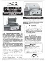
Fig. 8-1 type coupleur rapide de fi l de point culminant d’I
Valve
de
décompression
QCC
Type 1
Valve
Ajustage de précision
en laiton de fi l de
point culminant
Indicateur
de niveau
de liquide
(facultatif)
Écrou de main avec le
l de point culminant.
Régulateur
Passage
Tuyau
Volant de commande
main dans le sens des aiguilles d’une montre pour engager les
ls et pour serrer jusqu’à ce que douillettement. L’utilisation des
pinces ou de la clé ne devrait pas être nécessaire. Seulement
le propane marqué par cylindres doit être employé.
Pour débrancher: Tournez l’écrou de main dans le sens
contraire des aiguilles d’une montre jusqu’à isolé (fi g. 8-1).
Important: Avant d’employer le gril, et ensuite chaque
fois que le cylindre est enlevé et rattaché,
examinez tous les raccordements pour déceler
les fuites. Arrêtez les valves de gril et ouvrez
la valve principale de cylindre, puis vérifi ez
les raccordements avec de l’eau savonneux.
Réparez toutes les fuites avant d’allumer le
gril.
ATTENTION: Tournez toujours la valve principale de cylindre
de propane au loin après chaque utilisation,
et avant de déplacer le gril et le cylindre, ou
débrancher l’accouplement. Cette valve doit
rester fermée et le cylindre a débranché alors
que l’appareil n’est pas en service, quoique
l’écoulement de gaz soit arrêté par un dispositif
de sûreté quand le coupleur est débranché.
Inspectez soigneusement l’ensemble de tuyau chaque fois
avant que le gaz soit allumé. Un tuyau criqué ou frangé devrait
être remplacé immédiatement.
Si l’appareil est stocké à l’intérieur, le cylindre doit être débranché
et enlevé. Des cylindres doivent être stockés hors des portes, hors
de l’extension des enfants, et ne doivent pas être stockés dans un
bâtiment, le garage, ou n’importe quel autre secteur inclus.
POUR VOTRE SÛRETÉ
a. Ne stockez pas un cylindre de gaz disponible de propane
dessous ou ne vous approchez pas de cet appareil.
b. Ne remplissez jamais cylindre au delà de 80 pour cent de
plein.
c. SI L’INFORMATION DANS “A” ET “B” N’EST PAS SUIVIE
EXACTEMENT, UN FEU CAUSANT LA MORT OU DES
DOMMAGES SÉRIEUX PEUT SE PRODUIRE.
IMPORTANT POUR VOTRE SÛRETÉ
LISEZ ET SUIVEZ TOUS LES AVERTISSEMENTS ÉQUIPÉS DE VOTRE CYLINDRE DE GAZ DE PROPANE.
En actionnant cet appareil avec un cylindre de gaz de propane ON DOIT observer ces instructions et avertissements.
LE MANQUE DE FAIRE AINSI PEUT AVOIR COMME CONSÉQUENCE UNE INCENDIE OU UNE EXPLOSION SÉRIEUSE.
CYLINDRE ET CONDITIONS ET
CARACTÉRISTIQUES DE CONNECTEUR
a. Des cylindres et les valves de gaz de propane doivent être
maintenus en bon état et doivent être remplacés s’il y a
des dommages évidents au cylindre ou à la valve.
b. Ce gril, une fois utilisé avec un cylindre, devrait être relié à
un gallon de la norme 5 (20lb.) cylindre de gaz de propane
équipé d’un OPD (remplissez au-dessus du niveau le
dispositif d’empêchement). L’OPD a été exigé sur tous les
cylindres vendus depuis octobre 1.1998 pour empêcher le
remplissage excessif.
c. Les dimensions de cylindre devraient être approximativement
12"(30.5cm) de diamètre et 18" (45.7cm) hauts. Des
cylindres doivent être construits et marqués selon les
caractéristiques pour des cylindres de gaz de propane du
département des ETATS-UNIS du transport (D.O.T.) ou
le niveau national du Canada, du CAN/CSA-B339, des
cylindres, des sphères et des tubes pour le transport des
marchandises dangereuses.
d. Le cylindre doit inclure un collier pour protéger la valve
de cylindre et le circuit d’alimentation de cylindre doit être
assuré le retrait de vapeur.
e. Le régulateur de pression et l’ensemble de tuyau (
g. 8-
1
) fourni avec cet appareil à cuire extérieur de gaz doivent
être utilisés. Les régulateurs d’original et de pression de
remplacement et les ensembles de tuyau doivent être ceux
indiqués par le fabricant pour le raccordement avec un
dispositif se reliant de cylindre identifi é comme type I par la
norme ANSI Z 21.58-2007/CGA 1.6-2007 avec la norme ANSI
Z 21.58a -1998 d’addenda et CGA 1.6a - M98.
f. La valve de cylindre de gaz de propane doit être équipée
d’un dispositif d’accouplement de raccordement de
cylindre, décrit comme type I dans la norme défi nie dans le
e. de paragraphe ci-dessus. Ce dispositif est généralement
décrit comme coupleur rapide de fi l de point culminant.
g. Si votre cylindre de gaz de propane vient avec une prise
de la poussière, placez le bouchon anti-poussière sur la
sortie de valve de cylindre toutes les fois que le cylindre
n’est pas en service.
OPÉRATION DE COUPLEUR RAPIDE
Pour relier le regulator/hose à l’ajustage de précision de
valve de cylindre de gaz de propane: Serrez l’écrou de main
sur le régulateur au-dessus de l’ajustage de précision de fi l
de point culminant sur la valve de cylindre. Tournez l’écrou de
1
2
3
4
UTILISATION SÛRE ET ENTRETIEN DES CYLINDRES DE GAZ DE PROPANE
9
U
L
Fig. 9-1 Type I Acme thread quick coupler
Pressure
relief
valve
QCC
Type 1
valve
Brass Acme
thread fi tting
Liquid level
indicator
(optional)
Hand nut with Acme
thread
Regulator
Vent
Hose
Hand wheel
The use of pliers or a wrench should not be necessary. Only
cylinders marked “propane” may be used.
To disconnect: Turn the hand nut counterclockwise until
detached (Fig. 9-1).
Important: Before using the unit, and after each time the
cylinder is removed and reattached, check
the hose for wear (see a.) and check all
connections for leaks. Turn off the unit valves
and open the main cylinder valve, then check
connections with soapy water. Repair any
leaks before lighting the unit.
CAUTION: Always turn the propane cylinder main valve
off after each use, and before moving the unit
and cylinder or disconnecting the coupling.
This valve must remain closed and the
cylinder disconnected while the appliance
is not in use, even though the gas fl ow is
stopped by a safety feature when the coupler
is disconnected.
Carefully inspect the hose assembly each time before the
gas is turned on. A cracked or frayed hose should be replaced
immediately.
If the appliance is stored indoors, the cylinder must be
disconnected and removed.
Cylinders must be stored out of
doors, out of the reach of children, and must not be stored
in a building, garage, or any other enclosed area.
FOR YOUR SAFETY
a. DO NOT store a spare propane-gas cylinder under or
near this appliance.
b. NEVER fi ll the cylinder beyond 80-percent full.
c. IF THE INFORMATION IN a. AND b. IS NOT FOLLOWED
EXACTLY, A FIRE CAUSING DEATH OR SERIOUS
INJURY MAY OCCUR.
IMPORTANT FOR YOUR SAFETY
READ AND FOLLOW ALL WARNINGS PROVIDED WITH THE PROPANE-GAS CYLINDER.
When operating this appliance with a propane-gas cylinder, these instructions and warnings MUST be observed.
FAILURE TO DO SO MAY RESULT IN A SERIOUS FIRE OR EXPLOSION.
CYLINDER/CONNECTOR REQUIREMENTS
a. Propane-gas cylinders, valves, and hoses must be
maintained in good condition and must be replaced if
there is visible damage to either the cylinder or valve. If the
hose is cut or shows excessive abrasion or wear, it must
be replaced before using the gas appliance (see e.).
b. This unit, when used with a cylinder, should be connected
to a standard 5-gallon (20 lb.) propane-gas cylinder
equipped with an OPD (Overfi ll Prevention Device).
The OPD has been required on all cylinders sold since
October 1,1998, to prevent overfi lling.
c. Cylinder dimensions should be approximately 12" (30.5
cm) in diameter and 18" (45.7 cm) high. Cylinders must
be constructed and marked in accordance with the
Specifi cations for Propane Gas Cylinders of the U.S.
Department of Transportation (D.O.T.) or the National
Standard of Canada, CAN/CSA-B339, Cylinders,
Spheres, and Tubes for Transportation of Dangerous
Goods.
d. The cylinder must include a collar to protect the cylinder
valve, and the cylinder supply system must be arranged
for vapor withdrawal.
e. The pressure regulator and hose assembly (Fig. 9-1)
supplied with this outdoor-cooking gas appliance must
be used. Original and replacement pressure regulator
and hose assemblies must be those specifi ed by the
manufacturer for connection with a cylinder connecting
device identifi ed as Type I by the ANSI Z 21.58-2005/CGA
1.6-2005 (see PARTS LIST for ordering information).
f. The propane-gas cylinder valve must be equipped with a
cylinder connection coupling device, described as Type
I in the standard defi ned in paragraph e. above. This
device is commonly described as an Acme thread quick
coupler.
g. If the propane-gas cylinder comes with a dust plug, place
the dust cap on the cylinder valve outlet whenever the
cylinder is not in use.
QUICK COUPLER OPERATION
To connect the regulator/hose assembly to the propane-
gas cylinder valve fi tting: Press the hand nut on the regulator
over the Acme thread fi tting on the cylinder valve. Turn the hand
nut clockwise to engage the threads and tighten until snug.
SAFE USE & MAINTENANCE OF PROPANE-GAS CYLINDERS
10
GRILL NOTES PAGE
Please use this page to record any information about your grill that you may want to have at hand.
11
4. Using a
3
/
8
" socket, remove the orifi ce from
the valve. Access this through the hole in the
forward fi rebox plate (see PARTS LIST and
Fig. 11-1). Check the number stamped on
the face of the orifi ce (see Table 1). Repeat
for each burner as necessary.
5. If the barbecue does not have the proper orifi ces
installed for the gas supply you intend to use,
replace them with the correct orifi ces. Some
orifi ces were supplied with the barbecue. They
may also be obtained from the conversion kit
or supplied by your local dealer.
Note: A regulator hose will need to be connected
for conversion to propane gas.
6. After checking the
orifice drill size
or replacing the
orifice, replace
the burner over
the orifi ce fi tting,
sliding it forward,
from behind the
forward fi re wall, so the orifi ce is centered
inside the burner gas inlet, and set it gently
onto the rear burner-support. The threaded
studs on the bottom back of the burner must
each fi t through their respective holes in the
rear burner-support. This is critical to the safe
function of the barbecue. Finally, re-attach the
cotter pins from step 3 around the studs (see
Fig. 11-1).
MAIN BURNER AIR SHUTTER ADJUSTMENT
INSTALL THE VAPORIZER PANELS
Place the vaporizer panels directly on the support
bracket above the burners. The panels allow heat
from the burners to be evenly distributed throughout
the cooking area. The panels are stainless steel and
will heat and cool quickly, making your barbecue
very responsive to the changes you specify in
CHECKING/CONVERTING THE BURNER ORIFICES
MAIN BURNER ORIFICE SIZE CHECKING/
CONVERSION
Before beginning, make sure you have the proper
tools for the task.
This task requires:
a #2 Phillips-head screwdriver
• a deep
3
/
8
" nut driver with a spacer (#6 nut)
Note: It may be necessary to remove the rotisserie
rod before beginning this procedure.
1. Remove cooking grids & vaporizer panels from the
barbecue.
2. Turn the burner valves to the OFF position.
Pull the valve knobs from their stems and
set them aside. Using a Phillips screwdriver,
unscrew the face fastener screws, (located
on the sides of the face) and remove the face
from the barbecue. Retain the screws and fi nish
washers for reattaching the face.
Note: Carefully, lift the face away from the frame.
The spark generator for the ignition system
is attached to the inside of the face panel.
The spark generator knob need not be
detached, but the wires must be unplugged
from the generator before the face is
completely removed (see Fig. 11-2).
3. Remove the two cotter pins from underneath the
rear burner support and set them aside. Then
carefully lift the burner from the rear burner-
support and out from the hole in the forward fi re
wall (see Fig. 11-1).
Fig. 11-3 - Burner orifi ce diagram
Orifi ce
Burner
Valve
Fig. 11-2
Spark generator
Removing/inserting main burner.
Hole with
orifi ce
Burner
support
Cotter
pins
Fig. 11-1
Burner
support
12
grill temperature. They are rust resistant and may
be cleaned with standard oven cleaners. Some
discoloring will be seen with use. This is normal for
stainless steel and does not affect the function.
ADJUSTING YOUR BARBECUE
Important: This appliance may not light or heat
evenly or cook properly unless the
air shutters are adjusted following
installation (see AIR SHUTTER
ADJUSTMENT section).
Burner air shutters are easily accessed by removing
the front face panel. The air shutters are located on
the front portion of each burner and have a locking
screw that prevents the air shutter from inadvertent
movement (see Fig.
12-1).
To close or open the
air shutters, simply
loosen the locking
screw, using a long
stemmed Phillips
screwdriver, and
turn the air shutter
to open or close it.
Tighten the screws down when the desired setting
is achieved.
AIR SHUTTER ADJUSTMENT
Light the burner to be adjusted in accordance with
the LIGHTING INSTRUCTIONS and burn for 2
minutes with the burner control knob set to HIGH
and the oven open. After burning for 2 minutes,
open the air shutter until the fl ames lift off, or appear
not to be touching the burner. Then begin closing
the air shutter until the fl ames appear to burn while
CHECKING/CONVERTING THE BURNER ORIFICES (Cont.)
touching the burner ports (Fig. 12-2). You may then
see short yellow tips on the fl ames. If fl ames are a
lazy yellow, open the air shutters until the fl ame is
blue with yellow tipping.
Note: Barbecues in some installations achieve a
better air/gas mixture and will ignite more
quickly if the valve is fi rst turned beyond
HIGH to MEDIUM or LOW for lighting.
BACKBURNER ORIFICE SIZE CHECKING/
CONVERSION (IF EQUIPPED)
Before beginning, make sure you have the proper
tools for the task.
This task requires:
• a
1
/
4"
nutdriver
• a
3
/
8"
wrench or socket screwdriver
Note: It may be necessary to remove the
rotisserie rod before beginning this
procedure.
1. Remove the backburner assembly as follows:
a. Remove the backburner electrode mounting
screw (
1
/
4
" hex) (see Fig. 12-3) and loosen
the electrode. Draw the wire attached to
the electrode down through the slot in the
bottom of the bracket so that the left side of
the backburner is free to be removed.
b. Remove the backburner mounting screws
(
1
/
4
" hex) located at the left end of the
backburner assembly (see Fig. 12-3).
Remove electrode and backburner mounting screws.
Fig. 12-3
Mounting screws
Electrode
Ignitor
screw
Fig. 12-1
Locking
screw
Air shutter
Fig. 12-2 - Flame appearance diagram
Flame off ports
Flame on ports
13
c. Carefully pull the left end of the backburner
forward until the burner can be moved to the
left pulling it free from the orifi ce located on
the right side (see Fig.
13-1).
d. Using a
3
/
8
" socket, remove the orifi ce from the
orifi ce holder and check the number stamped
on the face.
2. If an orifi ce change is necessary, replace the
orifi ce with the correctly sized one.
3. Replace the backburner assembly and the
electrode by reversing the procedure in steps
a. through c..
CHECKING/CONVERTING THE BURNER ORIFICES (Cont.)
The backburner orifi ce can be seen on the
right side after removing the backburner.
Backburner
Orifi ce
Fig. 13-1
SIDEBURNER ORIFICE SIZE CHECKING/
CONVERSION (IF EQUIPPED)
Suggested Tools:
a pair of needle-nose pliers
• a
5
/
16
" hex nut driver
Note: It may be necessary to remove the rotisserie
rod before beginning this procedure.
1. Lift the sideburner lid. Then remove the grill and
sideburner cap and set them aside.
2. Locate and remove
the cotter pin from the
sideburner assembly
underneath the sideburner
shelf using needle-nose
pliers (Fig. 13-2). Set it
aside.
3. From the top of the
sideburner shelf lift the sideburner upward while
rotating the attached tubing underneath away
from the orifi ce near the cart wall. Set it aside.
Note: To protect the manifold threads when placing
the new orifi ce, start the threading manually,
and then tighten with the nut driver.
4. Use the nut driver to remove the exposed orifi ce
and replace it with the correct orifi ce for the gas
being converted to. (see Table 1 for correct orifi ce
sizes based on burner type and gas type).
Note: While the sideburner is still removed it may
be convenient to adjust the sideburner air
shutter.
5. Rotate the burner assembly back into place over
the orifi ce so that the orifi ce is centered deeply
into the burner pipe and the burner fi rmly seated
in the shelf.
6. Re-insert the cotter pin underneath the sideburner
assembly using needle-nose pliers. It may be
necessary to push downward on the burner
assembly from above to fully expose the cotter
pin hole. Rotate the inserted cotter pin so that it
is fl ush with the underside of the shelf.
7. Replace the burner cap by centering it on the
sideburner assembly and making sure it drops
in place.
8. Replace the grill with the grating running front to
back so that it drops fully down onto the shelf,
allowing the lid to close completely over it.
SIDEBURNER AIR SHUTTER ADJUSTMENT
The fl ames from a properly adjusted sideburner will
touch the burner ports and appear mostly blue with
light-yellow tips.
If the fl ames are orange, “lazy”, or
lift off the burner ports, then adjust
the sideburner air shutter using
the following steps (Fig. 13-3).
Sideburner adjustment is the
most accessible (not requiring
any hardware to be removed fi rst)
and is located underneath the sideburner shelf on
the left side of the barbecue, near the wall of the cart.
The sideburner air shutter can safely and easily be
adjusted while the sideburner is lit.
CAUTION: Do not touch the sideburner or the
shelf immediately around it. They will
be hot while adjusting the sideburner
air shutter.
1. Light the sideburner following the lighting
instructions in this manual.
2. Loosen the sideburner
air-shutter adjustment
screw, then use the tip
of the screwdriver to
open or close the air
shutter until the fl ames
appear blue and touch
the burner ports. (Fig.
13-4).
3. Re-tighten the adjustment screw.
Fig. 13-4
Close
Open
Fig. 13-3
Fig. 13-2
Cotter
pin
14
ÉCLAIRAGE ÉLECTRONIQUE
1. Ouvrez tous les couvercles et enlevez toutes les couvertures
des brûleurs que vous souhaitez vous allumer.
2. Arrêtez tous les boutons de commande de gaz à leurs
positions.
3. Allumez le gaz à sa source.
Note: Aucune matière que la méthode d’éclairage
vous emploient,
n’allument pas
le gaz à plus
d’un brûleur à la
fois. Les brûleurs
adjacents de
barbecue croix-
mettront à feu
et l’écoulement
de gaz peut être
restreint.
ATTENTION: Si les brûleurs ne s’allument pas dans 5
secondes, enfoncez le bouton de commande
et tournez le bouton à AU LOIN. ATTENDEZ
5 MINUTES avant de répéter l’étape 5. Si
vous sentez le gaz suivez les instructions
sur la couverture de ce manuel. Si les
brûleurs ne s’allument toujours pas après
que plusieurs tentatives, se rapportent aux
instructions pour l’ÉCLAIRAGE MANUEL.
4. Enfoncez le bouton de commande pour que le brûleur
soit allumé et tournez-le dans la position LÉGÈRE de
HI, puis appuyez sur le bouton d’allumage. Une fois que
le brûleur s’allume, libérez le bouton d’allumage.
5. Répétez l’étape 4 pour que chaque brûleur additionnel soit
s’est allumé.
POUR LE PROPANE SEULEMENT
Les réservoirs de propane sont équipés d’un dispositif
d’arrêt de sûreté qui peut ne pas causer le bas ou aucun gaz
pressure/fl ame aux brûleurs si le fonctionnement et allumer
des instructions ne sont pas suivis exactement (voir la note
importante dans la section de dépannage pour plus de
détails.)
Note: Les barbecues dans quelques installations réalisent
un meilleur mélange d’air/gas et mettront à feu plus
rapidement si le bouton de commande de brûleur
est d’abord tourné au delà de la LUMIÈRE de HI
au BAS pour l’éclairage.
ÉCLAIRAGE MANUEL
ATTENTION: Attendez toujours 5 minutes le gaz à l’espace
libre après que n’importe quelle tentative non
réussie d’éclairage.
1. Suivez les étapes 1 à 4 (à gauche).
2. Insérez un allumeur brûlant de butane de long-baril, une
allumette brûlante de long-tige, ou une allumette brûlante
tenue par un support de prolongation de fi l (Fig. 14-2)
par les grilles à cuire au brûleur (Fig. 14-3). Pour des
backburners, tenez la fl amme contre le matériel perforé
du brûleur arrière. Pour des sideburners, tenez la fl amme
contre le brûleur.
3. Tout en tenant l’allumette ou la fl amme plus légère à côté
du brûleur, enfoncez le bouton de commande approprié
de brûleur et tournez-le dans le sens contraire des
aiguilles d’une montre dans la position LÉGÈRE de HI.
Quand les lumières de brûleur, enlèvent l’allumeur ou
s’assortissent.
4. Si le brûleur ne s’allume pas, enfoncez immédiatement
le bouton et tournez le bouton de commande de brûleur
à AU LOIN. ATTENDEZ 5 MINUTES avant de répéter
les étapes 2 à 4 des INSTRUCTIONS MANUELLES
d’ÉCLAIRAGE.
COUPER LE GRIL
Pour couper le gril, enfoncez chaque bouton de commande
de valve et tournez-le dans le sens des aiguilles d’une montre
à la position de repos.
Fermez toujours la valve à l’offre de gaz après chaque
utilisation du barbecue.
RAPPELEZ-VOUS: POUR L’ÉCLAIRAGE MANUEL SÛR, PLACEZ
Un ALLUMEUR BRÛLANT D’ALLUMETTE OU De BUTANE PRÈS
Du BRÛLEUR - ALLUMEZ ALORS Le GAZ
(voyez Fig. 14-3).
Fig. 14-2 - Support d’allumette
Lisez l’instruction entière avant que s’allumant et suivez ces instructions chaque fois vous lumière le barbecue.
ALLUMER DES INSTRUCTIONS (D’ALLUMAGE)
Fig. 14-3 - Éclairage manuel
Fig. 14-1 - Valve control knob
OFF
HI
LIGHT
LOW
TO
TURN OFF
TO TURN ON
Read setting
here
HIGH to
LIGHT
Read setting
here
TO TURN OFF
TO TURN ON
High to
light
15
MANUAL LIGHTING
CAUTION: Always wait fi ve minutes for gas to clear
after any unsuccessful lighting attempt.
1. Follow steps 1 through 4 (left).
2. Insert either a burning long-barrel butane lighter,
a burning long-stem match, or a burning match
held by a wire extension holder (Fig. 15-2) through
the cooking grids to the burner (Fig. 15-3).
For backburners, hold the flame against the
perforated material of the backburner.
For sideburners, hold the fl ame against the burner.
3. While holding the match or lighter fl ame next to
the burner, depress the appropriate burner control
knob and turn it counterclockwise to the HI LIGHT
position. When the burner lights, remove the lighter
or match.
4. If the burner does not light, IMMEDIATELY depress the
knob and turn the burner control knob to OFF. WAIT
FIVE MINUTES before repeating steps 2 through 4
of the MANUAL LIGHTING INSTRUCTIONS.
Note: Some installations achieve a better air/gas
mixture and may ignite quicker if the burner
control knob is fi rst turned beyond HI LIGHT
to LOW for lighting.
ELECTRONIC LIGHTING
1. Open all lids and remove all covers from the burners
you wish to light.
2. Turn all gas control knobs to their OFF positions.
3. Turn on the gas at its source.
Note: No matter which lighting method you use,
DO NOT turn
on the gas to
more than one
burner at a time.
Adjacent grill
burners will
cross-ignite, and
gas flow may
be restricted.
CAUTION: If the burners do not light within five
seconds, depress the control knob
and turn the knob to OFF. WAIT FIVE
MINUTES before repeating step 4. If you
smell gas, follow the instructions on the
cover of this manual. If the burners still do
not light after several attempts, refer to the
instructions for MANUAL LIGHTING.
4. Depress the control knob for the burner to be lit
and turn it to the HI LIGHT position, then press the
ignition button. Once the burner lights, release the
ignition button.
5. Repeat step 4 for each additional burner to be lit.
FOR PROPANE ONLY
Propane tanks are equipped with a safety shutdown
device that may cause low or no gas pressure/fl ame
at the burners if operating and lighting instructions
are not followed exactly (See important note in the
TROUBLESHOOTING section for more details.)
REMEMBER: FOR SAFE MANUAL LIGHTING, PLACE A
BURNING MATCH OR BUTANE LIGHTER BESIDE THE
BURNER - THEN TURN ON THE GAS (see Fig. 15-3).
Fig. 15-2 - Match holder
Read entire instructions before lighting, and follow these instructions each time you light the grill.
LIGHTING (IGNITION) INSTRUCTIONS
Fig. 15-3 - Manual lighting
Fig. 15-1 - Valve control knob
OFF
HI
LIGHT
LOW
TO
TURN OFF
TO TURN ON
Read setting
here
HIGH to
LIGHT
Read setting
here
TO TURN OFF
TO TURN ON
High to
light
SHUTTING OFF THE GRILL
To shut off the grill, push in each valve control knob and
turn it clockwise to the OFF position.
Always close the valve to the gas supply after each use
of the grill.
16
Each time you use the barbecue, make sure that:
1. The area around the barbecue is clear of fl ammable
vapors, liquids, and substances such as gasoline,
yard debris, wood, etc.
2. There is no blockage of the airfl ow through the vent
space located below the face of the unit.
3. When using propane gas:
a. The special ventilation openings in the enclosure
should be kept free and clear of debris
(see PLANNING THE LOCATION OF THE
BARBECUE).
b. If connected to a propane cylinder, the rubber
hose attached to the regulator should be carefully
inspected before each use.
c. The propane cylinder, regulator, and rubber hose should
be installed in a location not subject to heating above
125° F (51° C).
4. The burner fl ames burn evenly along both sides of
each burner with a steady fl ame, which is mostly
blue with yellow tipping. (Refer to section on AIR
SHUTTER ADJUSTMENT.) If burner fl ames are not
normal, check the orifi ce and burner for insects or
insect nests.
5. The inline gas valve or gas cylinder valve is always
shut OFF when the barbecue is not in use.
6. The drip collector hole is clear and unobstructed.
Excessive grease deposits can result in a grease
re.
7. The barbecue is free and clear from combustible
materials, gasoline, and other fl ammable vapors
and liquids.
BARBECUE SAFETY INFORMATION & MAINTENANCE
WARNING
NEVER cover the entire cooking or grill surface with griddles or pans. Overheating will occur and
burners will not perform properly when combustion heat is trapped below the cooking surface.
CAUTION: NEVER spray water on a hot gas unit.
DRIP COLLECTION SYSTEM
The drip collector in this barbecue is part of the unit’s
main frame and is located below the burners. The drip
collector has one hole that will allow excess drippings to
fall through during cooking, while separating the fi rebox
from the drip tray. Clean the drip tray after each use.
The drip collector allows you to brush or scrape residue
from the barbecue’s inner liner into the drip tray.
Following the manufacturers instructions and regular
cleaning of the barbecue’s interior with oven cleaner,
will help to prevent grease fi res.
Periodically check the burners to make sure they
are clear of debris. Properly adjusted burner fl ames
burn evenly along both sides of each burner with
a steady fl ame (mostly blue with yellow tipping). If
burner fl ames are not normal, check the orifi ce and
burner for insects or insect nests. (See section on
CHECKING/CONVERTING THE BURNER ORIFICES
for instructions on burner removal and replacement.)
Check the burner ports at least annually for blockage by
removing the burner (see orifi ce changing instructions)
and visually inspect the gas intake tube for insects
and nests. A clogged tube can lead to a fi re beneath
the grill.
9. Do not operate the sideburner with its cover
closed.
8. Do not operate the backburner with its cover
installed.
17
ROTISSERIE INSTRUCTIONS
USING THE BACKBURNER AND ROTISSERIE
Rotisserie cooking with the backburner is
accomplished without use of the main burners. Follow
the steps in the appropriate sections below to set up
and use these accessories.
SET UP
1. Remove the cooking grids from the barbecue,
if necessary, to obtain maximum clearance for
larger cuts. The fl avor grids may also be removed
if required.
Tip: Aluminum foil or a baking pan may be
placed over the main burners, a little
forward of center, to catch excess drippings
from the meat.
2. Attach the rotisserie motor to the rotisserie
mounting on the right side of your barbecue by
sliding the bracket attached to the motor housing
onto the tab on the right of the barbecue so that
the spit rod will fi t into the motor drive socket from
the left.
3. Follow the LIGHTING INSTRUCTIONS to light
the backburner.
4. Allow the backburner to preheat for approximately
10 minutes on HI LIGHT setting.
PUTTING THE MEAT ON THE SPIT ROD
1. Slide the meat and spit prongs onto the spit rod
so the meat is centered and balanced as well
as possible.
2. Tighten the spit prongs into place so that the
meat remains in a fi xed position on the rod and
the meat rotates with the rod.
RUNNING THE ROTISSERIE
1. Place the pointed end of the spit rod into the motor
drive socket and rest the handle end of the spit
rod in the spit bracket on the right side of the
barbecue.
2. Plug in (if necessary) and turn on the rotisserie
motor.
3. Use a standard roasting guide to estimate the
length of time for your meat. A meat thermometer
may also be used to tell when your favorite cuts are
cooked to your liking. When testing temperatures
with a thermometer, turn off the rotisserie motor
and turn the backburner on LOW. This will keep
the meat from over cooking on one side.
Note: When burning properly, the backburner
grating will glow red. The fi rst time it is used
the backburner may smoke a little.
Important: Operate the backburner with the oven
closed. This simulates an oven effect
and helps your meat cook faster.
Constant rotation of the spit assures
even cooking and maximum retention
of juices.
Note: On large cuts of meat or whole turkeys, it
may be necessary to reduce the heat from
your backburner. Cooking food at a lower
temperature for a longer period of time will
keep the outer surface from burning while
cooking the interior of the meat.
Spit rod
Knob
Spit prongs
Stainless
steel motor
18
RIGID SHELF INSTALLATION
Shelf support screws
View from under right shelf
This barbecue comes with two (2) rigid shelves that
must be attached. These can be attached using the
four support screws provided and a Phillips-head
screw driver.
1.
Hold the shelf inverted so that one of the corner
holes in the shelf lines up with the appropriate
upper screw hole in the barbecue.
2. Insert the screw, but do not tighten all the way so
that the shelf can be easily rotated around the fi rst
screw.
3. Line up the second corner hole in the shelf with
the remaining upper screw hole in the barbecue.
Insert a screw and tighten.
Note: You may lift the edge of the shelf upward
to gain better access during much of the
tightening of this screw.
4. Finally, insert the bottom screws on the left and right
side of the shelf and securely tighten all screws.
To detach, reverse the process above.
This barbecue comes with two (2) rigid shelves that
must be attached. These can be attached using the
four support screws provided and a Phillips-head
screwdriver.
1. Insert the top two screws into the side of the
barbecue and screw them in about half way.
2. Line up the larger, bottom portion of the two
keyhole openings with the two top screws and fi t
the two keyhole openings over the two screws.
With the shelf pushed all the way against the
side of the barbecue, lower the shelf so that the
screws lock into the narrower, upper portions of
the keyholes.
Note: The shelf will now stay in place on it’s
own.
3. Insert the bottom two screws into their holes and
tighten them all the way.
4. Finally, tighten the upper two screws,
completely.
To detach, reverse the process above.
19
THE COOKING GRID LIFTER
Hold the grid lifter by gripping the center section with the
prongs pointing down (use an oven mitt or heavy glove
if the grill is hot). Insert the notched end of the grid lifter
into the cooking grid, in front of the midway point (front to
back; Fig. 19-3), and central (left to right; Fig. 19-4).
Twist the grill lifter (clockwise or counterclockwise) so
the handle is parallel to the grill rods. This “seats” the
spiked end of the grid lifter between two rods, enabling
you to safely lift out the grid. Lift slowly and adjust the
grid lifter, if necessary, for balance.
Placement of the grid lifter in cooking grid
Fig. 19-3
Fig. 19-4
THE DRIP PAN
The drip collection system allows you to brush or scrape
excess dried residue from the grilling area directly into
the drip pan (see PARTS LIST for drip pan location).
To simplify cleanup when using the rotisserie, you may
place a baking pan or foil under the rotisserie on top of
the burners to collect the drippings. Clean the drip pan
after each use.
THE WARMING RACK
The warming rack (Fig. 19-2) is packed separately.
To install the warming rack, lift the front of the rack
up slightly and insert the rack hangers into the two
holes in the back of the inner oven hood just above the
backburner. Then lower the front of the rack into a level
position to lock the rack in place.
To remove the warming rack, lift up on the front of the
rack until the rack hangers pull free from their supporting
holes.
Note: Removing the warming rack before using the
rotisserie will leave more clearance for the
meat being cooked.
Fig. 19-2 Warming rack in place inside oven
THE VAPORIZER PANEL(S)
Place each vaporizer panel directly on a burner or burner
pair. Center each panel over the burner, oriented as
shown in Fig. 19-1.
Note: This allows heat from the burners to be evenly
distributed throughout the cooking area. The
vaporizer panels heat and cool quickly, making
the grill very responsive to the changes in heat
from the burners.
Fig. 19-1
ACCESSORIES
20
Fig. 20-1 - Wipe with grain
PROTECTING YOUR APPLIANCE FROM THE
WEATHER
An optional heavy-duty cover will protect your
appliance’s fi nish and protect your investment. The
water repellent cover will protect your appliance
from the weather. Always cover your appliance
when not in use. (Allow to cool before covering.)
Please specify the model number and serial
number of your appliance when ordering a cover.
CARE AND CLEANING
Stainless steel surfaces when exposed to
temper
atures produced by the grilling process will
change color. The stainless steel will change color
from silver to brown and blue. This can be removed by
using Fire Magic Stainless Steel Cleaner (3581-1).
Clean your appliance by fi rst using Fire Magic
Barbecue and Grill Cleaner (part #3580-1) to
remove grease and dirt. Always wipe with the grain
(See Fig. 20-1). Next, use Fire Magic Stainless
Steel Cleaner (3581-1) to restore the stainless steel
color (Note: not for mirror fi nish). Finish by wiping
your appliance down using Fire Magic Polish Wipes
(3586-1). To clean the mirror panel, use a quality
brand glass cleaner only, not any of the cleaners
mentioned above.
Clean your appliance at least once a month.
If your appliance is installed in a seaside (salt air) or
poolside (chlorine) location, it will be more susceptible
to corrosion and must be maintained/cleaned more
frequently. Do not store chemicals (such as chlorine
or fertilizer) near your stainless steel appliance.
Due to the nature of stainless steel, surface iron
oxide deposits may appear. Do not be alarmed –
these deposits are removable with stainless-steel
cleaner through prompt and periodic maintenance.
If not attended to promptly, permanent pitting may
occur.
Check and clean the burner ports and burner carry-
over slits for blockage at least annually by removing
the burner (see orifi ce changing instructions) and
visually inspecting the burner inlet for insects and
nests. A clogged burner can lead to a fi re in the
bottom of the appliance.
The inside of the appliance may be cleaned
periodically with oven cleaner if desired. Follow the
oven cleaner instructions for proper use.
Be careful not to get oven cleaner on the outside
surface of the appliance as it can permanently
damage the fi nish.
By following these recommendations, you will enjoy
the beauty and convenience of your appliance for
many years to come.
Wipe with grain
CARE & CLEANING
  • Page 1 1
  • Page 2 2
  • Page 3 3
  • Page 4 4
  • Page 5 5
  • Page 6 6
  • Page 7 7
  • Page 8 8
  • Page 9 9
  • Page 10 10
  • Page 11 11
  • Page 12 12
  • Page 13 13
  • Page 14 14
  • Page 15 15
  • Page 16 16
  • Page 17 17
  • Page 18 18
  • Page 19 19
  • Page 20 20
  • Page 21 21
  • Page 22 22

American Outdoor 24PC Owner's manual

Category
Barbecues & grills
Type
Owner's manual
This manual is also suitable for

Ask a question and I''ll find the answer in the document

Finding information in a document is now easier with AI

in other languages