Amantii INSERT-26-3825 Owner's manual

Category
Fireplaces
Type
Owner's manual
1
malfunction and result in serious injury and/or property damage.
WARNING: All electric heaters have hot or sparking parts inside. Do not use it in areas where
gasoline, paint or flammable liquids are stored.
and/or result in a safety hazard.
Read these instructions completely before beginning installation. Failure to follow them could
cause a heater
WARNING: This heater is tested and listed for use only with the optional accessories listed in
these instructions. Use of optional accessories not specifically tested for this heater could void
the heater warranty
ELECTRIC FIREPLACES
ZECL-26-2923, ZECL-30-3226, ZECL-33-3624, ZECL-39-4134, ZECL-2939
INSERT-26-3825, INSERT-30-4026, INSERT-33-4230
ZECL-26--2923-FLUSHMT, ZECL-30-3226-FLUSHMT
SAFETY INFORMATION AND INSTALLATION MANUAL
ZECL-30-3226-WHTGLS, INSERT-30-4026-WHTGLS, ZECL-39-4134-WHTGLS
2
Keep this manual for future reference.
SAFETY INFORMATION
When using electrical heaters, basic precautions, like the ones listed below, should always be followed in order to
reduce the risk of fire, electric shock and injury.
1. Read all instructions before using this heater.
2. Keep combustible materials, such as furniture, pillows, bedding, papers, clothes and curtains at least 3 feet from the
front of the heater; keep them away from sides and rear as well.
3. Always unplug heater when it’s not in use.
4. Do not operate the fireplace insert if it has a damaged cord or plug, after it has malfunctioned, or if the unit has been
dropped or damaged in any way.
5. Do not use the heater outdoors.
6. This heater is not intended for use in bathrooms, laundry areas and similar indoor locations. Never place the heater
where it may fall into a bathtub or other water containers.
7. Do not run the cord under carpeting. Do not cover the cord with throw rugs, runners or anything else. Arrange the
cord away from traffic areas where it could be tripped over.
8. To disconnect the heater, turn the controls to "OFF" before removing the plug from the outlet.
9. Do not insert or allow foreign objects to enter any ventilation or exhaust opening, as this may cause an electric
shock, fire or damage to the heater.
10. To prevent a possible fire, do not block air intakes in any manner.
11. A heater has hot or sparking parts inside. Do not use it in areas where gasoline, paint or flammable
liquids are used or stored.
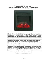
Due to high temperatures, the insert should be located out of
traffic and away from furniture and draperies.
The insert can become very hot when running. Keep children and
adults away from hot surfaces to avoid burns or clothing ignition. The
insert will remain hot for a time after shutdown. Allow surfaces to cool
before touching.
Do not place clothing or other flammable material on or near the
insert. Never place any objects on the insert.
3
12. Use this heater only as described in this manual. Any other use not recommended by the manufacturer may cause
fire, electric shock or injury to persons.
13. Avoid the use of an extension cord because the extension cord may overheat and cause a fire. If you have to use
an extension cord, the cord should be No. 14 AWG minimum size and rated not less than 1875 WATTS.
14. Always use a properly grounded, protected (fuse or circuit breaker), and polarized outlet.
15. Always use ground fault protection where it is required by electrical codes.
16. Always disconnect the power before performing any cleaning, maintenance or relocation of the heater.
17. To prevent a possible fire, do not burn wood or other materials in this heater.
18 To prevent electric shock or fire, always use a certified electrician, should new circuits or outlets
be required.
19. When transporting or storing the heater, keep it in a dry place, free from excessive vibration.
LISTING APPROVALS
This heater has been tested in accordance with the CSA Standards for fixed and location-dedicated electric room
heaters in the United States. All components are UL or CSA safety certified.
Voltage: 120 AC,
Hz: 60
Watts: 1500
Amps: 15
Note: This heater must be electrically wired and grounded in accordance with local codes or, in the absence of local
codes, with National Electric Code.
4
NOTE: This appliance must be electrically
wired and grounded in accordance with
local codes. In the absence oflocal codes,
us the current CSA C22.1 Canadian Elec-
trical Code in Canada or the ANSI/NFPA
States.
This appliance has been tested in accor-
dance with the UL Standand 2021 for
appliances in the United States and Cana-
da. If you need assistance during installa-
W(") D(") H(")
ZECL-26-2923 27 1/8 9 3/4 22 3/4
The rough wall opening size of the fireplace.
W
D
H
ZECL-26-2923
Built-in Appliance
120V AC, 60 Hz
12A
1500 W
HIGH 1500W
LOW 750W
18W
30W
4W
29 1/4" or 74.3 cm
23 1/2" or 59.8 cm
9 3/4" or 24.6 cm
56 Lbs or 25 Kg
Left side
74 3/4" or 190 cm
27 1/8"×22 3/4" or 69 cm×57.8 cm
Description
Voltage
Amps
Watts
HEATER
No HEATER
Motor HEATER
Motor Flame
Appliance Width
Cord Length
Rough Wall Opening Size
Appliance Height
Appliance Depth
Gross Weight
Plug Location
23" (598mm)
29 1/4" (743mm)
22 1/2" (567mm)
9 1/2" (246mm)
25 1/2" (641.6mm)
Front View
Top View
Side View
8 1/2" (221mm)
21" (533mm)
11 3/8" (287mm)
5
NOTE: This appliance must be electrically
wired and grounded in accordance with
local codes. In the absence oflocal codes,
us the current CSA C22.1 Canadian Elec-
trical Code in Canada or the ANSI/NFPA
States.
This appliance has been tested in accor-
dance with the UL Standand 2021 for
appliances in the United States and Cana-
da. If you need assistance during installa-
W(") D(") H(")
ZECL-30-3226 31 1/4 9 3/4 25 1/4
The rough wall opening size of the fireplace.
W
D
H
ZECL-30-3226
Built-in Appliance
120V AC, 60 Hz
12A
1500 W
HIGH 1500W
LOW 750W
18.5W
30W
4W
32 1/2" or 82.6 cm
26" or 66.1 cm
9 3/4" or 24.6 cm
64 Lbs or 29 Kg
Left side
74 3/4" or 190 cm
31 1/4"×25 1/4" or 79.5 cm×64.2 cm
Plug Location
Cord Length
Rough Wall Opening Size
Appliance Width
Appliance Height
Appliance Depth
Gross Weight
HEATER
No HEATER
Motor HEATER
Motor Flame
Description
Voltage
Amps
Watts
25 5/8" (661mm)
32 1/2" (826mm)
24 3/4" (631mm)
9 3/4" (246mm)
29 1/2" (746mm)
Front View
Top View
Side View
24 5/8" (626mm)
13" (330mm)
8 1/2" (221mm)
NOTE: This appliance must be electrically
wired and grounded in accordance with
local codes. In the absence oflocal codes,
us the current CSA C22.1 Canadian Elec-
trical Code in Canada or the ANSI/NFPA
States.
This appliance has been tested in accor-
dance with the UL Standand 2021 for
appliances in the United States and Cana-
da. If you need assistance during installa-
W(") D(") H(")
ZECL-33-3624 33 5/8 9 3/4 22 3/4
The rough wall opening size of the fireplace.
W
D
H
ZECL-33-3624
36" (913mm)
24" (611mm)
31 3/4" (806mm)
22 1/4" (567mm)
9 3/4" (297mm)
Top View
Front View Side View
30" (762mm)
11 1/2" (294mm)
8 1/2" (221mm)
Built-in Appliance
120V AC, 60 Hz
12A
1500 W
HIGH 1500W
LOW 750W
19W
30W
4W
36" or 91.3 cm
24" or 61.1 cm
9 3/4" or 24.6 cm
65 Lbs or 29.5 Kg
Left side
74 3/4" or 190 cm
33 5/8"×22 3/4" or 85.5 cm×57.8 cm
Rough Wall Opening Size
Appliance Depth
Gross Weight
Plug Location
Cord Length
Motor HEATER
Motor Flame
Appliance Width
Appliance Height
Amps
Watts
HEATER
No HEATER
Description
Voltage
6
NOTE: This appliance must be electrically
wired and grounded in accordance with
local codes. In the absence oflocal codes,
us the current CSA C22.1 Canadian Elec-
trical Code in Canada or the ANSI/NFPA
States.
This appliance has been tested in accor-
dance with the UL Standand 2021 for
appliances in the United States and Cana-
da. If you need assistance during installa-
W(") D(") H(")
ZECL-39-4134 39 1/2 9 3/4 32 3/8
The rough wall opening size of the fireplace.
W
D
H
ZECL-39-4134
Built-in Appliance
120V AC, 60 Hz
12A
1500 W
HIGH 1500W
LOW 750W
20W
30W
4W
41" or 104.2 cm
34 1/2" or 87.5 cm
9 3/4" or 24.6 cm
92.7 Lbs or 42 Kg
Left side
74 3/4" or 190 cm
39 1/2"×32 3/8" or 100.3 cm×82.1 cm
Plug Location
Cord Length
Rough Wall Opening Size
Appliance Width
Appliance Height
Appliance Depth
Gross Weight
HEATER
No HEATER
Motor HEATER
Motor Flame
Description
Voltage
Amps
Watts
32" (810mm)
41" (1042mm)
37 1/2" (955mm)
34 1/2" (875mm)
9 3/4" (247mm)
Front View Side View
Top View
32 1/2" (826mm)
20 1/4" (516mm)
8 1/2" (221mm)
7
NOTE: This appliance must be electrically
wired and grounded in accordance with
local codes. In the absence oflocal codes,
us the current CSA C22.1 Canadian Elec-
trical Code in Canada or the ANSI/NFPA
States.
This appliance has been tested in accor-
dance with the UL Standand 2021 for
appliances in the United States and Cana-
da. If you need assistance during installa-
W(") D(") H(")
ZECL-2939 26 1/8 9 3/4 38 1/8
The rough wall opening size of the fireplace.
W
D
H
ZECL-2939
Built-in Appliance
120V AC, 60 Hz
12A
1500 W
HIGH 1500W
LOW 750W
18W
30W
4W
29 1/2" or 75 cm
39 1/8" or 99.5 cm
9 3/4" or 24.6 cm
75 Lbs or 34 Kg
Left side
74 3/4" or 190 cm
26 1/8"×38 1/8" or 66.4 cm×96.8 cm
Cord Length
Rough Wall Opening Size
Appliance Height
Appliance Depth
Gross Weight
Plug Location
No HEATER
Motor HEATER
Motor Flame
Appliance Width
Voltage
Amps
Watts
HEATER
Description
29 1/2" (750mm)
39 1/4" (995mm)
24 1/4" (616mm)
37 3/4" (958mm)
9 3/4" (247mm)
Front View Side View
Top View
21 1/2" (546mm)
26 3/4" (680mm)
8 1/2" (221mm)
8
NOTE: This appliance must be electrically
wired and grounded in accordance with
local codes. In the absence oflocal codes,
us the current CSA C22.1 Canadian Elec-
trical Code in Canada or the ANSI/NFPA
States.
This appliance has been tested in accor-
dance with the UL Standand 2021 for
appliances in the United States and Cana-
da. If you need assistance during installa-
W(") D(") H(")
INSERT-26-3825 27 1/8 9 3/4 17 1/4
The rough wall opening size of the fireplace.
W
D
H
Built-in Appliance
120V AC, 60 Hz
12A
1500 W
HIGH 1500W
LOW 750W
18W
30W
4W
38" or 96.5 cm
25" or 63.5 cm
9 3/4" or 24.6 cm
61.7 Lbs or 28 Kg
Left side
74 3/4" or 190 cm
27 1/8"×17 1/4" or 69 cm×43.8 cm
HEATER
Description
Voltage
Amps
Watts
No HEATER
Motor HEATER
Motor Flame
Appliance Width
Appliance Height
Appliance Depth
Gross Weight
Plug Location
Cord Length
Rough Wall Opening Size
INSERT-26-3825
25" (635mm)
38" (965mm)
16 3/4" (427.8mm)
9 3/4" (246.8mm)
25 1/4" (641.6mm)
Front View Side View
Top View
1" (25.4mm)
23 3/4" (603mm)
9 1/2" (241.9mm)
8 1/2" (221mm)
9
NOTE: This appliance must be electrically
wired and grounded in accordance with
local codes. In the absence oflocal codes,
us the current CSA C22.1 Canadian Elec-
trical Code in Canada or the ANSI/NFPA
States.
This appliance has been tested in accor-
dance with the UL Standand 2021 for
appliances in the United States and Cana-
da. If you need assistance during installa-
W(") D(") H(")
INSERT-30-4026 31 1/4 9 3/4 19 5/8
The rough wall opening size of the fireplace.
W
D
H
INSERT-30-4026
Built-in Appliance
120V AC, 60 Hz
12A
1500 W
HIGH 1500W
LOW 750W
18.5W
30W
4W
40" or 101.5 cm
26" or 66.1 cm
9 3/4" or 24.6 cm
76.1 Lbs or 34.5 Kg
Left side
74 3/4" or 190 cm
31 1/4"×19 5/8" or 79.5 cm×49.8 cm
Cord Length
Rough Wall Opening Size
Appliance Height
Appliance Depth
Gross Weight
Plug Location
No HEATER
Motor HEATER
Motor Flame
Appliance Width
Voltage
Amps
Watts
HEATER
Description
40" (1015mm)0
26" (661mm)
29 1/2" (747mm)
19 1/4"(488mm)
9 3/4" (247mm)
Front View
Top View
Side View
1" (25.4mm)
26 3/4" (682mm)
11 1/2" (293mm)
8 1/2" (221mm)
10
NOTE: This appliance must be electrically
wired and grounded in accordance with
local codes. In the absence oflocal codes,
us the current CSA C22.1 Canadian Elec-
trical Code in Canada or the ANSI/NFPA
States.
This appliance has been tested in accor-
dance with the UL Standand 2021 for
appliances in the United States and Cana-
da. If you need assistance during installa-
W(") D(") H(")
INSERT-33-4230 33 5/8 9 3/4 22 3/4
The rough wall opening size of the fireplace.
W
D
H
INSERT-33-4230
42" (1066mm)
31 3/4" (806mm)
22 1/4" (568mm)
30" (762mm)
1" (25.4mm)
9 3/4" (247mm)
Front View Side View
Top View
8 1/2"(221mm)
29 3/4" (756mm)
11 3/4" (298mm)
Built-in Appliance
120V AC, 60 Hz
12A
1500 W
HIGH 1500W
LOW 750W
19W
30W
4W
42" or 106.6 cm
30" or 76.2 cm
9 3/4" or 24.6 cm
77.2 Lbs or 35 Kg
Left side
74 3/4" or 190 cm
33 5/8"×22 3/4" or 85.5 cm×57.8 cm
Gross Weight
Plug Location
Cord Length
Rough Wall Opening Size
Motor Flame
Appliance Width
Appliance Height
Appliance Depth
Watts
HEATER
No HEATER
Motor HEATER
Description
Voltage
Amps
11
NOTE: This appliance must be electrically
wired and grounded in accordance with
local codes. In the absence oflocal codes,
us the current CSA C22.1 Canadian Elec-
trical Code in Canada or the ANSI/NFPA
States.
This appliance has been tested in accor-
dance with the UL Standand 2021 for
appliances in the United States and Cana-
da. If you need assistance during installa-
W(") D(") H(")
ZECL-26-2923-FLUSHMT
27 1/8 9 3/4 22 3/4
The rough wall opening size of the fireplace.
W
D
H
ZECL-26-2923-FLUSHMT
Built-in Appliance
120V AC, 60 Hz
12A
1500 W
HIGH 1500W
LOW 750W
18W
30W
4W
29 1/4" or 74.3 cm
23 1/2" or 59.8 cm
9 3/4" or 24.6 cm
56 Lbs or 25 Kg
Left side
74 3/4" or 190 cm
27 1/8"×22 3/4" or 69 cm×57.8 cm
Description
Voltage
Amps
Watts
HEATER
No HEATER
Motor HEATER
Motor Flame
Appliance Width
Cord Length
Rough Wall Opening Size
Appliance Height
Appliance Depth
Gross Weight
Plug Location
23 " (598mm)
29 1/4" (743mm)
22 1/2" (567mm)
9 3/4" (246mm)
25 1/2" (641.6mm)
Front View
Top View
Side View
8 1/2" (221mm)
21" (533mm)
11 1/8" (287mm)
12
NOTE: This appliance must be electrically
wired and grounded in accordance with
local codes. In the absence oflocal codes,
us the current CSA C22.1 Canadian Elec-
trical Code in Canada or the ANSI/NFPA
States.
This appliance has been tested in accor-
dance with the UL Standand 2021 for
appliances in the United States and Cana-
da. If you need assistance during installa-
W(") D(") H(")
ZECL-30-3226-FLUSHMT
31 1/4 9 3/4 25 1/4
The rough wall opening size of the fireplace.
W
D
H
ZECL-30-3226-FLUSHMT
Built-in Appliance
120V AC, 60 Hz
12A
1500 W
HIGH 1500W
LOW 750W
18.5W
30W
4W
32 1/2" or 82.6 cm
26" or 66.1 cm
9 3/4" or 24.6 cm
64 Lbs or 29 Kg
Left side
74 3/4" or 190 cm
31 1/4"×25 1/4" or 79.5 cm×64.2 cm
Plug Location
Cord Length
Rough Wall Opening Size
Appliance Width
Appliance Height
Appliance Depth
Gross Weight
HEATER
No HEATER
Motor HEATER
Motor Flame
Description
Voltage
Amps
Watts
26" (661mm)
32 1/2" (826mm)
24 3/4" (631mm)
9 3/4" (246mm)
29 1/2" (746mm)
Front View
Top View
Side View
24 5/8" (626mm)
13" (330mm)
8 1/2" (221mm)
13
LOCATING THE FIREPLACE INSERT
Heater must be placed so it remains level (use included level to verify). Leveling bolts are provided
on the base of the fireplace insert to insure proper leveling.
WARNING: RISK OF FIRE. MAINTAIN ALL SPECIFIED CLEARANCES
TO COMBUSTIBLES. FAILURE TO COMPLY WITH THESE
INSTRUCTIONS MAY CAUSE A FIRE OR CAUSE THE APPLIANCE TO
OVERHEAT. ENSURE ALL CLEARANCES (I.E. BACK, SIDE, TOP, VENT
MANTEL, FRONT, ETC.) ARE CLEARLY MAINTAINED.
APPLIANCE GRILLS (VENTS) LOCATED ON THE FRONT AND BACK OF THIS
ELECTRIC APPLIANCE CANNOT IN ANY WAY BE COVERED AS IT MAY
CREATE A FIRE HAZARD.
WHEN USING PAINT OR LACQUER TO FINISH THE AREA ABOVE THE INSERT, THE PAINT
OR LACQUER MUST BE HEAT RESISTANT TO PREVENT DISCOLORATION.
NOTICE: All clearances must be maintained to combustibles.
Illustrations throughout these instructions reflect typical installations
and are for design purposes only. Actual installations may vary slightly
due to individual preferences.
WARNING: Never locate this heater where it may fall into a bathtub or
any water container.
14
CLEARANCES WHEN BUILT-IN
UNPACKING AND TESTING THE FIREPLACE INSERT
Carefully remove the fireplace insert from the box.
Remove the packing screws from both sides of the insert
(see illustration to the right). Prior to installing the
fireplace insert, plug the unit into a 120-volt grounded
outlet and test operation. Test all aspects of its
operation (manual switches, remote, display
characteristics and heater) to make sure all components
operate correctly.
WALL
MANTEL(maximum 12" (305mm) deep
FLOOR
FRONT GLASS
APPLIANCE
SIDE VIEW
2"[50.8 mm]
The fireplace insert may be placed within a framed enclosure that is level, dry, and capable of supporting the weight of the appliance
and front glass. It may be placed directly on wood or a non-combustible surface (not on linoleum or carpet). The minimum clearance
from the top of the appliance to a mantel (combustible or non-combustible) is 2" (50.8mm). The sides and back must maintain 1" (25.4mm)
clearance to any material. The top must maintain a 3/8" (10mm) clearance to any material.
MINIMUM 3/8" (10mm) CLEARANCE TO TOP
OF APPLIANCE( combustible or non-combustible)
MINIMUM 1" (25.4mm) CLEARANCE TO
SIDES AND BACK OF APPLIANCE
(combustible or non-combustible)
15
INSTALLATION
CAUTION: The unit's power supply cord must be connected to a properly
grounded and protected 120-volt outlet. Always use ground fault protection where
required by the electrical code.
WARNING - RISK OF FIRE! To prevent a possible fire, do not block the grills,
louvers, or air openings on the fireplace insert in any manner.
WARNING - RISK OF FIRE! The power cord must not be pinched or placed
against a sharp edge. Secure the cord to avoid tripping or snagging thus reducing
the risk of fire, electric shock or personal injury. Do not run the cord under
carpeting. Do not cover the cord with throw rugs, runners or similar items.
Arrange the cord away from traffic areas where it could be tripped over.
This insert must be installed into an existing masonry or zero-clearance (metal) fireplace.
Select a suitable location that is not susceptible to moisture and is away from drapes, furniture and high traffic areas.
Note: Follow all national and local electrical codes.
16
INSTALLATION OVERVIEW – MASONRY FIREPLACES
2” (50mm) Minimum
HINT:
Paint the interior of the
fireplace with latex paint to
prevent fireplace odors
from entering the home.
Silicone
Leveling Bolts
HINT:
Close and seal the damper
to prevent air infiltration.
Cover plate is required if chimney
does not have suitable rain cap.
A Code-Conforming (jacketed, grounded) receptacle
may be placed within the fireplace. Do not place it above
the fireplace insert.
The surround glass extends 1"
below the base of the insert.
Attach the "This fireplace has been altered..." plate
to the fireplace (use two screws or other suitable
method). You may wish to place it in a location
where it will be covered by the surround glass.
Use one of the rear screws
on the insert to secure the
included tie-down bracket to
the fireplace. Once in place,
secure the bracket to the
fireplace floor to prevent the
insert from tipping. Secure
brackets to both sides.
17
INSTALLATION OVERVIEW – ZERO-CLEARANCE (METAL) FIREPLACES
2” (50mm)
Minimum
The log shelf,
screen, and doors
(if present) must
be removed.
HINT:
Paint the interior of the
fireplace with latex paint to
prevent fireplace odors
from entering the home.
HINT:
Close and seal the damper
to prevent air infiltration.
Cover plate is required if chimney
does not have suitable rain cap.
If the firebox steps down greater than
1", place shims (plywood, tile, etc.)
under the leveling bolts to provide
adequate leveling.
Silicone
The surround glass extends 1"
below the base of the insert.
A Code-Conforming (jacketed, grounded)
receptacle may be placed within the fireplace. Do
not place it above the fireplace insert.
Leveling Bolts
Attach the "This fireplace has been
altered..." plate to the fireplace (use
two screws or other suitable
method). You may wish to place it in
a location where it will be covered by
the surround glass.
Use one of the rear screws
on the insert to secure the
included tie-down bracket to
the fireplace. Once in place,
secure the bracket to the
fireplace floor to prevent the
insert from tipping. Secure
brackets to both sides.
18
OPTIONAL DECORATIVE INTERIORS
This insert is shipped with an under-lit log pre-installed. Glowing embers are also included with the fireplace insert
if you want a different appearance.
Glowing Embers
Removing The Log
The under-lit log is shipped in place. On newer units, the log has tabs on each side that hold it in place. Remove
Installing the Glowing Embers
Pour the glowing embers onto the tray as shown below. Feel free to use the combination of glowing embers you
find most appealing.
the black interior side panel (or carefully remove the tabs) to remove the log set. This is done by removing the two
screws holding the panel in place.
19
Harvest Moon Clear Sun Tea
OPERATING INSTRUCTIONS
REMOVING THE SURROUND GLASS
Before removing the surround glass, make sure to have a suitable location to place the surround glass once it is
removed. Do not place the glass on sharp or uneven areas that may chip or damage the tempered glass. Use both
hands to lift the surround glass directly up. The hooks on the glass will disengage from the pins that protrude from
the side of the insert.
REMOTE CONTROL OPERATION
1. For the remote to function make sure the heater is plugged in and main power switch is turned on.
Power switch is
located behind the
surround glass –
MAKE SURE IT IS
TURNED ON.
20
  • Page 1 1
  • Page 2 2
  • Page 3 3
  • Page 4 4
  • Page 5 5
  • Page 6 6
  • Page 7 7
  • Page 8 8
  • Page 9 9
  • Page 10 10
  • Page 11 11
  • Page 12 12
  • Page 13 13
  • Page 14 14
  • Page 15 15
  • Page 16 16
  • Page 17 17
  • Page 18 18
  • Page 19 19
  • Page 20 20
  • Page 21 21
  • Page 22 22
  • Page 23 23
  • Page 24 24
  • Page 25 25
  • Page 26 26
  • Page 27 27
  • Page 28 28

Amantii INSERT-26-3825 Owner's manual

Category
Fireplaces
Type
Owner's manual

Ask a question and I''ll find the answer in the document

Finding information in a document is now easier with AI