
FCC-B Radio Frequency Interference Statement
This equipment has been tested and found to comply with the limits for a class B digital
device, pursuant to part 15 of the FCC rules. These limits are designed to provide
reasonable protection against harmful interference in a residential installation. This
equipment generates, uses and can radiate radio frequency energy and, if not installed and
used in accordance with the instruction manual, may cause harmful interference to radio
communications. However, there is no guarantee that interference will occur in a particular
installation. If this equipment does cause harmful interference to radio or television
reception, which can be determined by turning the equipment off and on, the user is
encouraged to try to correct the interference by one or more of the measures listed below.
Reorient or relocate the receiving antenna.
Increase the separation between the equipment and receiver.
Connect the equipment into an outlet on a circuit different from that to which the
receiver is connected.
Consult the dealer or an experienced radio/ television technician for help.
Notice 1
The changes or modifications not expressly approved by the party responsible for
compliance could void the user’s authority to operate the equipment.
Notice 2
Shielded interface cables and A.C. power cord, if any, must be used in order to comply with
the emission limits.
VOIR LA NOTICE D’NSTALLATION AVANT DE RACCORDER AU RESEAU.
Micro-Star International
MS-7302
G52-73021X2
i

ii
Copyright Notice
The material in this document is the intellectual property of MICRO-STAR INTERNATIONAL.
We take every care in the preparation of this document, but no guarantee is given as to the
correctness of its contents. Our products are under continual improvement and we reserve
the right to make changes without notice.
Trademarks
All trademarks are the properties of their respective owners.
AMD
®
, Athlon™ Athlon™XP, Thoroughbred™ and Duron™ are registered trademarks of
AMD
®
Corporation.
Intel
®
and Pentium
®
are registered trademarks of Intel Corporation.
PS/2 and OS
®
/2 are registered trademarks of International Business Machines Corporation.
Microsoft
®
is a registered trademark of Microsoft Corporation. Windows
®
98/2000/NT/XP are
registered trademarks of Microsoft Corporation.
NVIDIA
®
, the NVIDIA logo, DualNet, and nForce are registered trademarks or trademarks of
NVIDIA
®
Corporation in the United States and/or other countries.
Netware
®
is a registered trademark of Novell, Inc.
Award
®
is a registered trademark of Phoenix Technologies Ltd.
AMI
®
is a registered trademark of American Megatrends Inc.
Kensington and MicroSaver are registered trademarks of the Kensington Technology
Group.
PCMCIA and CardBus are registered trademarks of the Personal Computer Memory Card
International Association.
Revision History
Revision Revision History Date
V1.0 First release January. 2008
V1.1 Update spec and add Korean March. 2008

Safety Instructions
Always read the safety instructions carefully.
Keep this User Manual for future reference.
Keep this equipment away from humidity.
Lay this equipment on a reliable flat surface before setting it up.
The openings on the enclosure are for air convection hence protects the equipment
from overheating. Do not cover the openings.
Make sure the voltage of the power source and adjust properly 110/220V before
connecting the equipment to the power inlet.
Place the power cord such a way that people can not step on it. Do not place
anything over the power cord.
Always Unplug the Power Cord before inserting any add-on card or module.
All cautions and warnings on the equipment should be noted.
Never pour any liquid into the opening that could damage or cause electrical shock.
If any of the following situations arises, get the equipment checked by a service
personnel:
- The power cord or plug is damaged.
- Liquid has penetrated into the equipment.
- The equipment has been exposed to moisture.
- The equipment does not work well or you can not get it work according to User
Manual.
- The equipment has dropped and damaged.
- The equipment has obvious sign of breakage.
Do not leave this equipment in an environment unconditioned, storage temperature
above 60° C (140°F), it may damage the equipment.
CAUTION: Danger of explosion if battery is incorrectly replaced. Replace only with
the same or equivalent type recommended by the manufacturer.
iii

WEEE Statement
ENGLISH
To protect the global environment and as an environmentalist, MSI must remind you
that...
Under the European Union ("EU") Directive on Waste Electrical and Electronic Equipment, Directive
2002/96/EC, which takes effect on August 13, 2005, products of "electrical and electronic equipment"
cannot be discarded as municipal waste anymore and manufacturers of covered electronic equipment will
be obligated to take back such products at the end of their useful life. MSI will comply with the product take
back requirements at the end of life of MSI-branded products that are sold into the EU. You can return
these products to local collection points.
DEUTSCH
Hinweis von MSI zur Erhaltung und Schutz unserer Umwelt
Gemäß der Richtlinie 2002/96/EG über Elektro- und Elektronik-Altgeräte dürfen Elektro- und
Elektronik-Altgeräte nicht mehr als kommunale Abfälle entsorgt werden. MSI hat europaweit
verschiedene Sammel- und Recyclingunternehmen beauftragt, die in die Europäische Union in Verkehr
gebrachten Produkte, am Ende seines Lebenszyklus zurückzunehmen. Bitte entsorgen Sie dieses
Produkt zum gegebenen Zeitpunkt ausschliesslich an einer lokalen Altgerätesammelstelle in Ihrer Nähe.
FRANÇAIS
En tant qu’écologiste et afin de protéger l’environnement, MSI tient à rappeler ceci...
Au sujet de la directive européenne (EU) relative aux déchets des équipement électriques et
électroniques, directive 2002/96/EC, prenant effet le 13 août 2005, que les produits électriques et
électroniques ne peuvent être déposés dans les décharges ou tout simplement mis à la poubelle. Les
fabricants de ces équipements seront obligés de récupérer certains produits en fin de vie. MSI prendra en
compte cette exigence relative au retour des produits en fin de vie au sein de la communauté européenne.
Par conséquent vous pouvez retourner localement ces matériels dans les points de collecte.
РУССКИЙ
Компания MSI предпринимает активные действия по защите окружающей среды, поэтому
напоминаем вам, что....
В соответствии с директивой Европейского Союза (ЕС) по предотвращению загрязнения
окружающей среды использованным электрическим и электронным оборудованием (директива
WEEE 2002/96/EC), вступающей в силу 13 августа 2005 года, изделия, относящиеся к
электрическому и электронному оборудованию, не могут рассматриваться как бытовой мусор,
поэтому производители вышеперечисленного электронного оборудования обязаны принимать его
для переработки по окончании срока службы. MSI обязуется соблюдать требования по приему
продукции, проданной под маркой MSI на территории EC, в переработку по окончании срока
службы. Вы можете вернуть эти изделия в специализированные пункты приема.
ESPAÑOL
MSI como empresa comprometida con la protección del medio ambiente, recomienda:
Bajo la directiva 2002/96/EC de la Unión Europea en materia de desechos y/o equipos electrónicos, con
fecha de rigor desde el 13 de agosto de 2005, los productos clasificados como "eléctricos y equipos
electrónicos" no pueden ser depositados en los contenedores habituales de su municipio, los fabricantes
de equipos electrónicos, están obligados a hacerse cargo de dichos productos al termino de su período
de vida. MSI estará comprometido con los términos de recogida de sus productos vendidos en la Unión
Europea al final de su periodo de vida. Usted debe depositar estos productos en el punto limpio
establecido por el ayuntamiento de su localidad o entregar a una empresa autorizada para la recogida de
estos residuos.
NEDERLANDS
Om het milieu te beschermen, wil MSI u eraan herinneren dat….
De richtlijn van de Europese Unie (EU) met betrekking tot Vervuiling van Electrische en Electronische
producten (2002/96/EC), die op 13 Augustus 2005 in zal gaan kunnen niet meer beschouwd worden als
vervuiling.
Fabrikanten van dit soort producten worden verplicht om producten retour te nemen aan het eind van hun
levenscyclus. MSI zal overeenkomstig de richtlijn handelen voor de producten die de merknaam MSI
dragen en verkocht zijn in de EU. Deze goederen kunnen geretourneerd worden op lokale
inzamelingspunten.
iv
Page is loading ...

vi
Table of Content
English...........................1
한국어............................15
Français.........................29
Deutsch .........................43
Русском.........................57
简体中文 ........................71
繁體中文 ........................83
日本語............................97

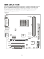
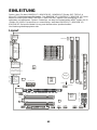
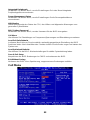
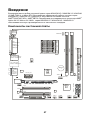
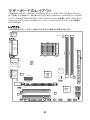
INTRODUCTION
Thank you for choosing the K9A2GM V2 / K9A2GM V3 / K9A2VM V2 series (MS-7302 v1.x)
Micro-ATX mainboard. The K9A2GM V2 / K9A2GM V3 / K9A2VM V2 series are design
based on AMD
®
780G/740/780V + AMD
®
SB700 chipsets for optimal system efficiency.
Designed to fit the advanced AMD
®
Athlon 64 X2 / Athlon 64 / AM2+ processor, the
K9A2GM V2 / K9A2GM V3 / K9A2VM V2 series deliver a high performance and
professional desktop platform solution.
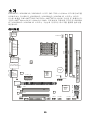
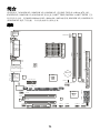
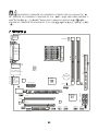
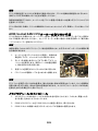
Layout
SOCKET AM2
BATT
+
IDE1
FDD 1
Top : mouse
Bottom:
keyboard
Top :
Parallel Port
Bottom:
COM portA
VGA port
Top: LAN Jack
Bottom: USB ports
T:
M:
B:
Line-In
Line-Out
Mic
T:RS-Out
M:CS-Out
B:SS-Out
Top:1394(optional)
Bottom: USB ports
AMD
780G/
740/
780V
AMD
SB700
PWR1
CPUFAN1
DIMM2
DIMM1
ATX1
SATA1
SATA2
SATA3
SATA4
JFP1JUSB1JUSB2JSPI1
J1394_1
(optional)
CD1
JAUD1
JSP1
PCI2
PCI1
PCIE16_X1
PCIE1_X1
JCOM2
JBAT1
JTPM1(optional)
SYSFAN1
JCI
JFP2
1

2
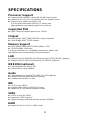
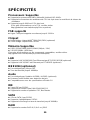
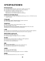
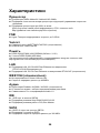
SPECIFICATIONS
Processor Support
z Supports AMD
®
Athlon64 / Athlon64 X2 /AM2+ processors
z Supports 4 pin CPU Fan Pin-Header with Fan Speed Control
z Supports up to 6000+ and higher CPU
(For the latest information about CPU, please visit
http://global.msi.com.tw/index.php?func=cpuform)
Supported FSB
z Hyper Transport support speed up to 3.0GHz
Chipset
z North Bridge: AMD
®
780G/740/780V chipset (optional)
z South Bridge: AMD
®
SB700 chipset
Memory Support
z DDR2 533/667/800/1066 SDRAM (240pin / 1.8V)
z 2 DDR2 DIMMs (4GB Max)
(For more information on compatible components, please visit
http://global.msi.com.tw/index.php?func=testreport)
LAN
z Supports LAN 10/100/1000 Fast Ethermet by RTL8111C/8111B (optional)
z Supports LAN 10/100 Fast Ethermet by RTL8101E (optional)
IEEE1394 (optional)
z Chip integrated by JMicron 381
z Transfer rate is up to 400Mb/s
Audio
z Chip integrated by Realtek
®
ALC888 / ALC662 (optional)
z Flexible 8-channel audio with jack sensing
z Compliant with Azalia 1.0 Spec
IDE
z 1 IDE port by SB700
z Supports Ultra DMA 33/66/100/133 mode
z Supports PIO, Bus Master operation mode
SATA
z 4 SATA II ports by SB700
z Supports 4 SATA II devices
z Supports storage and data transfers at up to 300MB/s
RAID
z Supports RAID 0/ 1/ 0+1 or JBOD mode

3
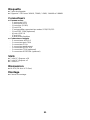
Floppy
z 1 floppy port
z Supports 1 FDD with 360KB, 720KB, 1.2MB, 1.44MB and 2.88MB
Connectors
z Back panel
- 1 PS/2 mouse port
- 1 PS/2 keyboard port
- 1 serial port (COM1)
- 1 VGA port
- 1 parallel port supporting SPP/EPP/ECP mode
- 1 IEEE 1394 port (optional)
- 4 USB 2.0 Ports
- 1 LAN jack
- 6 flexible audio jacks
z On-Board Pinheaders / Connectors
- 2 USB 2.0 pinheaders
- 1 COM port pinheader
- 1 CD-In connector
- 1 Front Panel Audio pinheader
- 1 SPDIF-Out pinheader
- 1 TPM pinheader (optional)
- 1 IEEE1394 pinheader (optional)
Slots
z 1 PCI Express x16 slot
z 1 PCI Express x1 slot
z 2 PCI slots
Form Factor
z M-ATX (24.4cm X 21.5cm)
Mounting
z 6 mounting holes

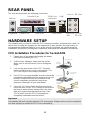
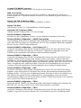
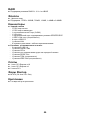
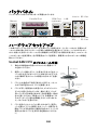
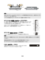
REAR PANEL
The rear panel provides the following connectors:
Mouse
Keyboard Serial Port VGA Port
Parallel Port 1394 Port
(optional)
USB Ports
LAN
Line-In RS-Ou
t
Line-Out
MI
C
CS-Ou
t
SS-Out
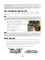
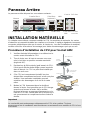
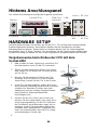
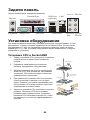
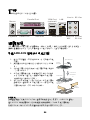
HARDWARE SETUP
This chapter tells you how to install the CPU, memory modules, and expansion cards, as
well as how to setup the jumpers on the mainboard. It also provides the instructions on
connecting the peripheral devices, such as the mouse, keyboard, etc. While doing the
installation, be careful in holding the components and follow the installation procedures.
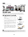
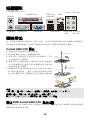
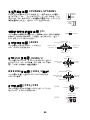
CPU Installation Procedures for Socket AM2
1. Please turn off the power and unplug the power
cord before installing the CPU.
2. Pull the lever sideways away from the socket.
Make sure to raise the lever up to a 90-degree
angle.
3. Look for the gold arrow of the CPU. The gold
arrow should point as shown in the picture. The
CPU can only fit in the correct orientation.
4. If the CPU is correctly installed, the pins should be
completely embedded into the socket and can not
be seen. Please note that any violation of the
correct installation procedures may cause
permanent damages to your mainboard.
5. Press the CPU down firmly into the socket and
close the lever. As the CPU is likely to move while
the lever is being closed, always close the lever
with your fingers pressing tightly on top of the
CPU to make sure the CPU is properly and
completely embedded into the socket.
Open the leve
r
90 degree
Sliding
the plate
Gold arrow
Correct CP
U
placement
O
Press down
the CPU
Close
the lever
Important:
Overheating will seriously damage the CPU and system. Always make sure the cooling fan
can work properly to protect the CPU from overheating.
4

Make sure that you apply an even layer of heat sink paste (or thermal tape) between the
CPU and the heatsink to enhance heat dissipation.
While replacing the CPU, always turn off the ATX power supply or unplug the power supply
power cord from the grounded outlet first to ensure the safety of CPU.
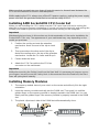
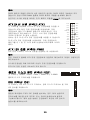
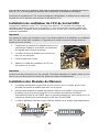
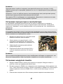
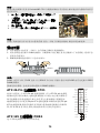
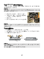
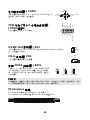
Installing AMD Socket AM2 CPU Cooler Set
When you are installing the CPU, make sure the CPU has a heat sink and a cooling fan
attached on the top to prevent overheating. If you do not have the heat sink and cooling fan,
contact your dealer to purchase and install them before turning on the computer.
Important:
Mainboard photos shown in this section are for demonstration of the cooler installation for
Socket AM2 CPUs only. The appearance of your mainboard may vary depending on the
model you purchase.
1. Position the cooling set onto the retention
mechanism. Hook one end of the clip to hook
first.
2. Then press down the other end of the clip to
fasten the cooling set on the top of the retention
mechanism. Locate the Fix Lever and lift up it.
3. Fasten down the lever.
4. Attach the CPU Fan cable to the CPU fan
connector on the mainboard.
Important:
While disconnecting the Safety Hook from the fixed bolt, it is necessary to keep an eye on
your fingers, because once the Safety Hook is disconnected from the fixed bolt, the fixed
lever will spring back instantly.
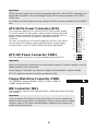
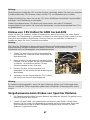
Installing Memory Modules
1. The memory module has only one notch on the center and will only fit in the right
orientation.
2. Insert the memory module vertically into the DIMM slot. Then push it in until the
golden finger on the memory module is deeply inserted in the DIMM slot. You can
barely see the golden finger if the memory module is properly inserted in the DIMM
slot.
3. The plastic clip at each side of the DIMM slot will automatically close.
V
o
lt
Notch
5

Important:
DDR2 memory modules are not interchangeable with DDR and the DDR2 standard is not
backwards compatible. You should always install DDR2 memory modules in the DDR2
DIMM slots.
To enable successful system boot-up, always insert the memory modules into the DIMM1
first.
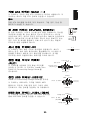
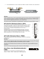
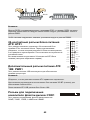
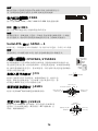
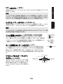
ATX 24-Pin Power Connector: ATX1
This connector allows you to connect an ATX 24-pin power supply.
To connect the ATX 24-pin power supply, make sure the plug of the
power supply is inserted in the proper orientation and the pins are
aligned. Then push down the power supply firmly into the
connector.
You may use the 20-pin ATX power supply as you like. If you like to
use the 20-pin ATX power supply, please plug your power supply
along with pin 1 & pin 13 (refer to the image at the right hand).
GND
GND
GND
PS-ON
#
GND
+3.3V
-12V
+3.3V
+3.3V
+3.3V
+5V
+5V
+5V
+5V
+5V
Res
PWR OK
GND
GND
GND
GND
5VSB
+12V
+12V
ATX 12V Power Connector: PWR1
This 12V power connector is used to provide power to the CPU.
GNDGND
+12V+12V
Important:
Make sure that all the connectors are connected to proper ATX power supplies to ensure
stable operation of the mainboard.
Power supply of 350 watts (and above) is highly recommended for system stability.
ATX 12V power connection should be greater than 18A.
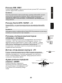
Floppy Disk Drive Connector: FDD1
This connector supports 360KB, 720KB, 1.2MB, 1.44MB or
2.88MB floppy disk drive.
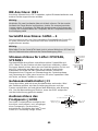
IDE Connector: IDE1
This connector supports IDE hard disk drives, optical disk drives and other
IDE devices.
Important:
If you install two IDE devices on the same cable, you must configure the
drives to cable select mode or separately to master / slave mode by setting
jumpers. Refer to IDE device documentation supplied by the vendors for
jumper setting instructions.
6

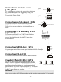
Serial ATA Connector: SATA1 ~ 4
This connector is a high-speed Serial ATA interface port. Each connector
can connect to one Serial ATA device.
Important:
Please do not fold the Serial ATA cable into 90-degree angle. Otherwise,
data loss may occur during transmission.
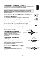
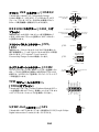
Fan Power Connectors: CPUFAN1,
SYSFAN1
The fan power connectors support system cooling fan with +12V.
When connecting the wire to the connectors, always note that the red
wire is the positive and should be connected to the +12V; the black
wire is Ground and should be connected to GND. If the mainboard
has a System Hardware Monitor chipset on-board, you must use a
specially designed fan with speed sensor to take advantage of the
CPU fan control.
GND
+12V
Sensor
Control
GND
+12V
Sensor
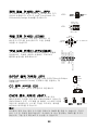
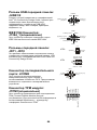
Chassis Intrusion Connector: JCI
This connector connects to the chassis intrusion switch cable. If the
chassis is opened, the chassis intrusion mechanism will be activated.
The system will record this status and show a warning message on
the screen. To clear the warning, you must enter the BIOS utility and
clear the record.
CINTR
U
GND
21
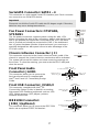
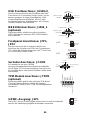
Front Panel Audio
Connector: JAUD1
This connector allows you to connect the
front panel audio and is compliant with
Intel
®
Front Panel I/O Connectivity Design
Guide.
(10)Line_JD
GND(2)
VCC5
MIC2_JD
NC
MIC_L(1)
Line-out_R
(9)Line-out_L
MIC_R
Front to Sense
Front USB Connector: JUSB1/2
This connector, compliant with Intel
®
I/O
Connectivity Design Guide, is ideal for connecting
high-speed USB interface peripherals such as USB
HDD, digital cameras, MP3 players, printers,
modems and the like.
(10)N.C.
VCC(2)
USB1-
US
B1+
GND
VCC(1)
USB0-
USB0+
GND
(9)Key,no pin
IEEE1394 Connector:
J1394_1(optional)
This connector allows you to connect the IEEE1394
device via an optional IEEE1394 bracket.
(10)GND
TPA-(2)
GND
TPB-
Cable power
TPA+(1)
GND
TPB
+
Cable power
(9)Key,no pin
7

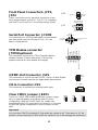
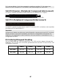
JFP2
Power
LED
Speaker
2
8
1
7
Front Panel Connectors: JFP1,
JFP2
These connectors are for electrical connection to the
front panel switches and LEDs. The JFP1 is compliant
with Intel
®
Front Panel I/O Connectivity Design Guide.
JFP1
HDD
LED
R
eset
Switch
Power
S
wit
c
h
Power
LED
19
10 2
+
+
+-
-
-
Serial Port Connector: JCOM2
This connector is a 16550A high speed communication
port that sends/receives 16 bytes FIFOs. You can
attach a serial device.
Key,no pin
SIN
DTR
D
S
R
CTS
DCD
SOUT
G
ND
RTS
RI
(10)
(2)
(1)
(9)
TPM Module connector:
JTPM1(optional)
This connector connects to a TPM (Trusted Platform
Module) module. Please refer to the TPM security
platform manual for more details and usages.
K
E
Y
G
N
D
G
N
D
14
3
V
d
u
a
l
/
3
V
_
S
T
B
2
V
C
C
3
S
I
R
Q
V
C
C
5
L
C
L
K
1
L
R
S
T
#
L
A
D
0
L
A
D
1
L
A
D
2
L
A
D
3
L
F
R
A
M
E
#
13
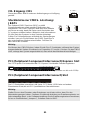
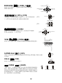
S/PDIF-Out Connector: JSP1
This connector is used to connect S/PDIF (Sony & Philips Digital
Interconnect Format) interface for digital audio transmission.
GND
VCC
SPDIF
CD-In Connector: CD1
This connector is provided for external audio input.
G
ND
LR
Clear CMOS Jumper: JBAT1
There is a CMOS RAM onboard that has a power supply
from an external battery to keep the data of system
configuration. With the CMOS RAM, the system can
automatically boot OS every time it is turned on. If you want
to clear the system configuration, set the jumper to clear
data.
Keep Data Clear Data
2
22
1
11
3
33
Important:
You can clear CMOS by shorting 2-3 pin while the system is off. Then return to 1-2 pin
position. Avoid clearing the CMOS while the system is on; it will damage the mainboard.
8

PCI (Peripheral Component Interconnect) Express Slot
The PCI Express slot supports the PCI Express interface expansion card.
The PCI Express x 16 slot supports up to 4.0 GB/s transfer rate.
The PCI Express x 1 slot supports up to 250 MB/s transfer rate.
PCI (Peripheral Component Interconnect) Slot
The PCI slot supports LAN card, SCSI card, USB card, and other add-on cards that
comply with PCI specifications.
Important:
When adding or removing expansion cards, make sure that you unplug the power supply
first. Meanwhile, read the documentation for the expansion card to configure any
necessary hardware or software settings for the expansion card, such as jumpers,
switches or BIOS configuration.
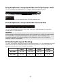
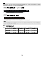
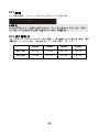
PCI Interrupt Request Routing
The IRQ, acronym of interrupt request line and pronounced I-R-Q, are hardware lines over
which devices can send interrupt signals to the microprocessor. The PCI IRQ pins are
typically connected to the PCI bus pins as follows:
Order1 Order2 Order3 Order4
PCI Slot1 INT A# INT B# INT C# INT D#
PCI Slot2 INT B# INT C# INT D# INT A#
9

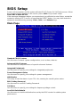
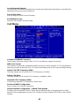
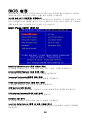
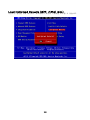
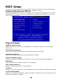
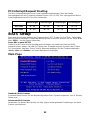
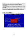
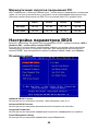
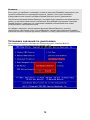
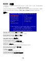
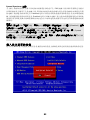
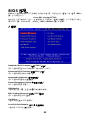
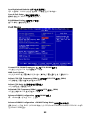
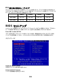
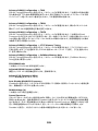
BIOS Setup
Power on the computer and the system will start POST (Power On Self Test) process. When
the message below appears on the screen, press <DEL> key to enter Setup.
Press DEL to enter SETUP
If the message disappears before you respond and you still wish to enter Setup, restart the
system by turning it OFF and On or pressing the RESET button. You may also restart the
system by simultaneously pressing <Ctrl>, <Alt>, and <Delete> keys.
Main Page
Standard CMOS Features
Use this menu for basic system configurations, such as time, date etc.
Advanced BIOS Features
Use this menu to setup the items of special enhanced features.
Integrated Peripherals
Use this menu to specify your settings for integrated peripherals.
Power Management Setup
Use this menu to specify your settings for power management.
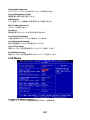
H/W Monitor
This entry shows the status of your CPU, fan, warning for overall system status.
BIOS Setting Password
Use this menu to set BIOS setting Password.
Cell Menu
Use this menu to specify your settings for frequency/voltage control.
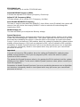
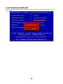
Load Fail-Safe Defaults
Use this menu to load the default values set by the BIOS vendor for stable system
performance.
10

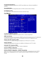
Load Optimized Defaults
Use this menu to load the default values set by the mainboard manufacturer specifically for
optimal performance of the mainboard.
Save & Exit Setup
Save changes to CMOS and exit setup.
Exit Without Saving
Abandon all changes and exit setup.
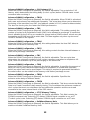
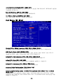
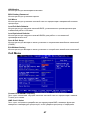
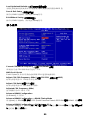
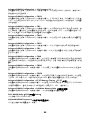
Cell Menu
Current CPU/DRAM Frequency
These items show the current clocks of CPU and Memory speed. Read-only.
AMD Cool’n’Quiet
This feature is especially designed for AMD processor, which provides a CPU temperature
detecting function to prevent your CPU from overheating due to the heavy working loading.
Adjust CPU FSB Frequency (MHz)
This item allows you to set the CPU FSB frequency (in MHz).
Adjust CPU Ratio
This item allows you to set the CPU frequency multiplier (ratio).
Adjusted CPU Frequency (MHz)
It shows the adjusted CPU frequency. Read-only.
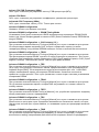
Advance DRAM Configuration
Press <Enter> to enter the sub-menu.
Advance DRAM Configuration -> DRAM Timing Mode
Setting to [Auto] enables DRAM CAS# Latency automatically to be determined by BIOS
based on the configurations on the SPD (Serial Presence Detect) EEPROM on the DRAM
module.
11

12
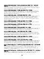
Advance DRAM Configuration -> CAS Latency (CL)
When the DRAM Timing sets to [Manual], the field is adjustable.This controls the CAS
latency, which determines the timing delay (in clock cycles) before SDRAM starts a read
command after receiving it.
Advance DRAM Configuration -> TRCD
When the DRAM Timing sets to [Manual], the field is adjustable. When DRAM is refreshed,
both rows and columns are addressed separately. This setup item allows you to determine
the timing of the transition from RAS (row address strobe) to CAS (column address strobe).
The less the clock cycles, the faster the DRAM performance.
Advance DRAM Configuration -> TRP
When the DRAM Timing sets to [Manual], this field is adjustable. This setting controls the
number of cycles for Row Address Strobe (RAS) to be allowed to precharge. If insufficient
time is allowed for the RAS to accumulate its charge before DRAM refresh, refresh may be
incomplete and DRAM may fail to retain data. This item applies only when synchronous
DRAM is installed in the system.
Advance DRAM Configuration -> TRAS
When the DRAM Timing sets to [Manual], this setting determines the time RAS takes to
read from and write to a memory cell.
Advance DRAM Configuration -> TRTP
When the DRAM Timing sets to [Manual], this setting controls the time interval between a
read and a precharge command.
Advance DRAM Configuration -> TRC
When the DRAM Timing sets to [Manual], the field is adjustable. The row cycle time
determines the minimum number of clock cycles a memory row takes to complete a full
cycle, from row activation up to the precharging of the active row.
Advance DRAM Configuration -> TWR
When the DRAM Timing sets to [Manual], the field is adjustable. It specifies the amount of
delay (in clock cycles) that must elapse after the completion of a valid write operation,
before an active bank can be precharged. This delay is required to guarantee that data in
the write buffers can be written to the memory cells before precharge occurs.
Advance DRAM Configuration -> TRRD
When the DRAM Timing sets to [Manual], the field is adjustable. Specifies the
active-to-active delay of different banks.
Advance DRAM Configuration -> TWTR
When the DRAM Timing sets to [Manual], the field is adjustable. This item controls the Write
Data In to Read Command Delay memory timing. This constitutes the minimum number of
clock cycles that must occur between the last valid write operation and the next read
command to the same internal bank of the DDR device.
Advance DRAM Configuration -> 1T/2T Memory Timing
When the DRAM Timing sets to [Manual], the field is adjustable. This field controls the
SDRAM command rate. Selecting [1T] makes SDRAM signal controller to run at 1T
(T=clock cycles) rate. Selecting [2T] makes SDRAM signal controller run at 2T rate.
Advance DRAM Configuration -> SoftWare Memory Hole
When the DRAM Timing sets to [Manual], the field is adjustable. This field allows you to
enable or disable SoftWare Memory Hole.

13
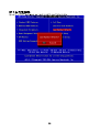
FSB/DRAM Ratio
This item allows you to set the FSB/DRAM ratio.
Adjusted DRAM Frequency (MHz)
It shows the adjusted DDR memory frequency. Read-only.
Adjust PCI-E Frequency (MHz)
This item allows you to set the PCI-E frequency (in MHz).
Auto Disable DRAM/PCI Frequency
This item is used to auto detect the DIMM/PCI slots. When set to [Enabled], the system will
remove (turn off) clocks from empty DIMM/PCI slots to minimize the electromagnetic
interference (EMI).
DRAM Voltage (V)
This item will allow you to adjust the Memory voltage.
Spread Spectrum
When the motherboard’s clock generator pulses, the extreme values (spikes) of the pulses
create EMI (Electromagnetic Interference). The Spread Spectrum function reduces the EMI
generated by modulating the pulses so that the spikes of the pulses are reduced to flatter
curves. If you do not have any EMI problem, leave the setting at Disabled for optimal system
stability and performance. But if you are plagued by EMI, set to Enabled for EMI reduction.
Remember to disable Spread Spectrum if you are overclocking because even a slight jitter
can introduce a temporary boost in clock speed which may just cause your overclocked
processor to lock up.
Important:
If you do not have any EMI problem, leave the setting at [Disabled] for optimal system
stability and performance. But if you are plagued by EMI, select the value of Spread
Spectrum for EMI reduction.
The greater the Spread Spectrum value is, the greater the EMI is reduced, and the system
will become less stable. For the most suitable Spread Spectrum value, please consult your
local EMI regulation.
Remember to disable Spread Spectrum if you are overclocking because even a slight jitter
can introduce a temporary boost in clock speed which may just cause your overclocked
processor to lock up.

Load Optimized Defaults
You can load the default values provided by the mainboard manufacturer for the stable
performance.
14
Page is loading ...
Page is loading ...
Page is loading ...
Page is loading ...
Page is loading ...
Page is loading ...
Page is loading ...
Page is loading ...
Page is loading ...
Page is loading ...
Page is loading ...
Page is loading ...
Page is loading ...
Page is loading ...

INTRODUCTION
Félicitations, vous venez d’acquérir une carte mère des séries Micro-ATX K9A2GM V2 /
K9A2GM V3 / K9A2VM V2 (MS-7302 v1.x). Les K9A2GM V2 / K9A2GM V3 / K9A2VM V2
séries sont basées sur les chipsets AMD
®
780G/740/780V + AMD
®
SB700 offrant un système
très performant. La carte fonctionne avec les processeurs AMD
®
Athlon 64 X2 / Athlon 64 /
AM2+, les K9A2GM V2 / K9A2GM V3 / K9A2VM V2 séries sont très performantes et offrent
une solution adaptée tant aux professionnels qu’aux particuliers.
Schéma
SOCKET AM2
BATT
+
IDE1
FDD 1
Top : mouse
Bottom:
keyboard
Top :
Parallel Port
Bottom:
COM portA
VGA port
Top: LAN Jack
Bottom: USB ports
T:
M:
B:
Line-In
Line-Out
Mic
T:RS-Out
M:CS-Out
B:SS-Out
Top:1394(optional)
Bottom: USB ports
AMD
780G/
740/
780V
AMD
SB700
PWR1
CPUFAN1
DIMM2
DIMM1
ATX1
SATA1
SATA2
SATA3
SATA4
JFP1JUSB1JUSB2JSPI1
J1394_1
(optional)
CD1
JAUD1
JSP1
PCI2
PCI1
PCIE16_X1
PCIE1_X1
JCOM2
JBAT1
JTPM1(optional)
SYSFAN1
JCI
JFP2
29
Page is loading ...
Page is loading ...
Page is loading ...
Page is loading ...
Page is loading ...
Page is loading ...
Page is loading ...
Page is loading ...
Page is loading ...
Page is loading ...
Page is loading ...
Page is loading ...
Page is loading ...
Page is loading ...
Page is loading ...
Page is loading ...
Page is loading ...
Page is loading ...
Page is loading ...
Page is loading ...
Page is loading ...
Page is loading ...
Page is loading ...
Page is loading ...
Page is loading ...
Page is loading ...
Page is loading ...
Page is loading ...
Page is loading ...
Page is loading ...
Page is loading ...
Page is loading ...
Page is loading ...
Page is loading ...
Page is loading ...
Page is loading ...
Page is loading ...
Page is loading ...
Page is loading ...
Page is loading ...
Page is loading ...
Page is loading ...
Page is loading ...
Page is loading ...
Page is loading ...
Page is loading ...
Page is loading ...
Page is loading ...
Page is loading ...
Page is loading ...
Page is loading ...
Page is loading ...
Page is loading ...
Page is loading ...
Page is loading ...
Page is loading ...
Page is loading ...
Page is loading ...
Page is loading ...
Page is loading ...
Page is loading ...
Page is loading ...
Page is loading ...
Page is loading ...
Page is loading ...
Page is loading ...
Page is loading ...
Page is loading ...
Page is loading ...
Page is loading ...
Page is loading ...
Page is loading ...
Page is loading ...
Page is loading ...
Page is loading ...
Page is loading ...
Page is loading ...
Page is loading ...
Page is loading ...
Page is loading ...
Page is loading ...
-
 1
1
-
 2
2
-
 3
3
-
 4
4
-
 5
5
-
 6
6
-
 7
7
-
 8
8
-
 9
9
-
 10
10
-
 11
11
-
 12
12
-
 13
13
-
 14
14
-
 15
15
-
 16
16
-
 17
17
-
 18
18
-
 19
19
-
 20
20
-
 21
21
-
 22
22
-
 23
23
-
 24
24
-
 25
25
-
 26
26
-
 27
27
-
 28
28
-
 29
29
-
 30
30
-
 31
31
-
 32
32
-
 33
33
-
 34
34
-
 35
35
-
 36
36
-
 37
37
-
 38
38
-
 39
39
-
 40
40
-
 41
41
-
 42
42
-
 43
43
-
 44
44
-
 45
45
-
 46
46
-
 47
47
-
 48
48
-
 49
49
-
 50
50
-
 51
51
-
 52
52
-
 53
53
-
 54
54
-
 55
55
-
 56
56
-
 57
57
-
 58
58
-
 59
59
-
 60
60
-
 61
61
-
 62
62
-
 63
63
-
 64
64
-
 65
65
-
 66
66
-
 67
67
-
 68
68
-
 69
69
-
 70
70
-
 71
71
-
 72
72
-
 73
73
-
 74
74
-
 75
75
-
 76
76
-
 77
77
-
 78
78
-
 79
79
-
 80
80
-
 81
81
-
 82
82
-
 83
83
-
 84
84
-
 85
85
-
 86
86
-
 87
87
-
 88
88
-
 89
89
-
 90
90
-
 91
91
-
 92
92
-
 93
93
-
 94
94
-
 95
95
-
 96
96
-
 97
97
-
 98
98
-
 99
99
-
 100
100
-
 101
101
-
 102
102
-
 103
103
-
 104
104
-
 105
105
-
 106
106
-
 107
107
-
 108
108
-
 109
109
-
 110
110
-
 111
111
-
 112
112
-
 113
113
-
 114
114
-
 115
115
-
 116
116


Ask a question and I''ll find the answer in the document
Finding information in a document is now easier with AI
in other languages
- français: MSI 7302-030R Manuel utilisateur
- Deutsch: MSI 7302-030R Benutzerhandbuch
- русский: MSI 7302-030R Руководство пользователя
- 日本語: MSI 7302-030R ユーザーマニュアル
Related papers
-
MSI G52-75011X7 Owner's manual
-
-
-
-
-
-
MSI 990FXA-GD80 Owner's manual
-
-
MSI Z68A-GD80 (B3) User manual
-
Other documents
-
Medion ms-7501M1 User manual
-
MATSONIC MS9107C User manual
-
Albatron PX915P4 PRO User manual
-
EVGA P55 Classified 200 (160-LF-E659) User manual
-
-
DFI 852GME-MGF Pro User manual
-
-
 Micro Star Computer G52-73601X1 User manual
-
BCM MX255D User manual
-
