Page is loading ...

Owner'sIVlanual/iVlanualDel Propietario
[
GarageDoorOpenerWiTHAssureLinkTM CONNECTiViTY
AbridordepuertadecocheraCONCONECTiVOAssureLinkTM
ForResidentialUseOnly/S61oparausoresidential
IViODEL/iViODELO139.30437
J=R
Z
i,m
m
gO
Z
rT'i
go
Z_
O
r""
Readandfollowall safetyrulesand operating
instructionsbefore firstuse of thisproduct.
Fastenthe manual nearthe garage doorafter
installation.
Periodic checksof the opener are requiredto
ensuresafeoperation.
DONOTenablethe Timer-to-Closefeatureif
youare installingthe garage dooropeneron a
one-piece door.TheTimer-to-Closeisto be
usedONLYwithsectionaldoors.
Leery seguirtodasiasregiasde seguridady
las instruccionesde operaci6n antesde usar
esteproductoporprimeravez.
Guardarestemanual cercade la puertade la
cochera.
Se debenrealizarrevisionesperi6dicasdei
abridor de puertasparaasegurar suoperaci6n
segura.
NOuso el caracteristicaTernporizadorpara
cierrase el abridor de la puertaes instalado
enun puertade un solapieza. E!caracteristica
ternporizador paracierraes SOLOpara uso
conpuertasseccionales.
SearsBrandsManagementCorporation, HoffrnanEstates,IL50179 U.S.A.
www.craftsman.com

TABLE OF CONTENTS
Introduction 2-7
Safetysymbol and signal word review ..................... 2
Preparing your garagedoor ............................. 3
Tools needed ........................................ 3
Planning ........................................... 4-5
Carton inventory ...................................... 6
Hardware inventory.................................... 7
Assembly 8-11
Assemblethe railand install the trolley .................... 8
Fastenthe rail to the motor unit .......................... 8
install the idler pulley .................................. 9
Install the chain/cable................................. 10
Tighten the chain .................................... 11
/nstallation 11-27
Installation safety instructions .......................... 11
Determinethe headerbracket location .................... 12
install the headerbracket .............................. 13
Attach the rail to the headerbracket...................... 14
Position the opener................................... 15
Hangthe opener..................................... 16
install the lights ..................................... 17
Attach the emergencyreleaserope and handle ............. 17
Fastenthe door bracket ............................. 18-19
Connectthe door arm to trolley ....................... 20-21
Attach thewarning labels .............................. 21
install the door control ................................ 22
install The Protector System_......................... 23-25
Electrical requirements................................ 26
Aligning the safety reversingsensors..................... 27
Adjustment 28-30
introduction ........................................ 28
Program the travel ................................... 29
Testthe safety reversalsystem.......................... 30
TestThe Protector System_ ............................ 30
Operation 31-35
Operationsafety instructions ........................... 31
Features ......................................... 31-32
Door control ........................................ 32
Motion-detecting control panelsetup ..................... 33
Programming ....................................... 34
To erasethe memory ................................. 34
To open the door manually............................. 35
Careofyour opener .................................. 35
Troubleshooting 38-37
Repair Parts 38-39
Rail assembly parts .................................. 38
installation parts ..................................... 38
Motor unit assembly parts ............................. 39
Accessories 40
Warranty 40
Notes 41
Repair Parts and Service
Back Cover
INTRODUCTION
Safety Symboland Signal Word Review
This garage door opener has beendesignedand tested to offer safeserviceprovided it is installed, operated,maintained and tested in
strict accordancewith the instructions and warnings contained in this manual.
Mechanical
Electrical
Whenyou seethese SafetySymbols and Signal Words on the
following pages,they will alertyou to the possibility of serious
injury or deathif you do not comply with the warnings that
accompanythem. Thehazardmay come from something
mechanicalor from electric shock. Readthe warnings carefully.
Whenyou seethis Signal Word on the following pages, it will
alertyou to the possibility of damageto your garagedoor and/or
the garagedoor opener if you do not comply with the cautionary
statements that accompany it. Readthem carefully.

Preparing your garage door
Beforeyou begin:
* Disable locks.
* Removeany ropesconnected to garage door.
, Complete the following test to make sureyour garage door is
balancedand is not sticking or binding:
1. Lift the door about halfwayas shown. Releasethe door. If
balanced,it should stay in place, supported entirely by its
springs.
2. Raiseand lower the door to see if there is any binding or
sticking.
If your door binds, sticks, or is out of balance,call a trained door
systems technician.
To prevent possible SERIOUSINJURYor DEATH:
* ALWAYScall atrained door systems technician if garage
door binds, sticks, or is out of balance.An unbalanced
garagedoor may NOTreversewhen required.
, NEVERtry to loosen, move or adjust garagedoor, door
springs, cables,pulleys, brackets or their hardware,ALL of
which are under EXTREMEtension.
, DisableALL locks and removeALL ropes connectedto
garagedoor BEFOREinstalling and operating garagedoor
opener to avoidentanglement.
To prevent damageto garage door and opener:
* ALWAYSdisable locks BEFOREinstalling and operatingthe
opener.
, ONLYoperate garagedoor opener at 120V, 60 Hzto avoid
malfunction and damage.
SectionaJ Door
One-Piece Door
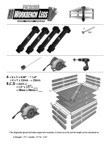
Too/sneeded
During assembly, installation and adjustment of the opener,
instructions will call for hand tools as illustrated below.
Stepladder
Carpenter's Level (__
(optional) Pencil
Tape Measure
Drill DrillBits3/16", WireCutters
O0 5/16",and5/32"
O0 _OsC,k_/_ _n,d_e,nc_dll2/i,, Pliers
Screwdriver
Adjustable End Wrench

P nnMg
identify the type and height of your garagedoor. Surveyyour
garageareato see if any of the conditions below apply to your
installation. Additional materials may be required.You may find it
helpful to refer back to this page andthe accompanying
illustrations asyou proceedwith the installation of your opener.
Dependingon your requirements,there are several installation
steps which may call for materialsor hardwarenot included in the
carton.
• Installation Step 1 - Lookat the wall or ceiling abovethe
garagedoor. Theheader bracketmust besecurelyfastenedto
structural supports.
• Installation Step 5 - Doyou havea finished ceiling in your
garage? if so, a support bracketand additional fastening
hardware may be required.
• installation Step 12- Dependingupon garageconstruction,
extension brackets or wood blocks maybe neededto install
sensors.
• installation Step 12- Alternate floor mounting of the safety
reversingsensor will require hardwarenot provided.
Doyou havean accessdoor in addition to the garage door? if
not, Model 139.53702 EmergencyKey Releaseis required. See
Accessoriespage.
Look at the garagedoor where it meetsthe floor. Any gap
betweenthe floor and the bottom of the door must not exceed
1/4" (6 mm). Otherwise,the safety reversal system may not
work properly. SeeAdjustment Step2. Flooror door should be
repaired.
SECTIONALDOORINSTALLATIONS
• Doyou havea steel, aluminum, fiberglass or glass panel door?
if so, horizontal and vertical reinforcement is required
(installation Step 8).
• Theopener should be installed abovethe center of the door. if
there is a torsion spring or center bearing plate in the way of
the headerbracket, it may be installed within 4 feet (1.22 m) to
the left or right of the door center.See installation Steps 1
and 8.
• If your door is more than 7 feet (2.13 m) high, see rail
extension kits listed on Accessories page.
SECTIONALDOORINSTALLATION
Horizontal and vertical reinforcement is
neededfor lightweight garage doors
(fiberglass, steel, aluminum, door with glass
panels, etc.) See page 18 for details.
Header Wall
Slack in chain tension is
normal when garage door
is closed.
FINISHEDCEILING
SuppoR bracket
& fastening
hardware is required. See
page 16.
OR
Torsion Spring
Sprin,
Motor Unit
Vertical Centerline
of Garage Door
Safety Reversing Sensor
Gap between floor and bottom
of the door must not exceed
1/4" (6 mm).
Wall-mounted
Door Control
h
Safety Reversing Sensor
Access Door
O
Header
Bracket
Rail Tab
CLOSEDPOSITION
Trolley
Garage Door
Spring
Door
Bracket
Cuwed
Door Arm
Chain
Emergency
Release
Rope & Handle

Planning(Continued)
ONE-PIECEDOORINSTALLATIONS
* Generally,a one-piecedoor does not require reinforcement, if
your door is lightweight, refer to the information relatingto
sectional doors in Installation Step 8.
* Dependingonyour door's construction, you may need
additional mounting hardwarefor the door bracket (Step8).
Without a properly working safety reversal system, persons
(particularly small children) could be SERIOUSLYINJUREDor
KILLEDby a closing garagedoor.
* Thegap betweenthe bottom of the garage door and the
floor MUST NOTexceed1/4" (6 mm). Otherwise,the safety
reversalsystem may NOTwork properly.
* Thefloor or the garage door MUSTbe repairedto eliminate
the gap.
ONE-PIECEDOORWITHOUTTRACK FINISHEDCEILING__
Support bracket _ _ ._-"_
& fastening _ _l_r _'
hardware is required. See "_
page 16.
Header Rail
W_sr
-- -_]1_-----f-_ is'c'lo_;d'................ Motor Unit
__L_ _ Wall-mounted Door
____,,,_- _-- __1 Door Bracket
Safety Reversing
Gap between floor Sensor
t and bottom of door must
Safety Reversing Sensor not exceed 1/4" (6 mm)
Door
CLOSED POSiTiON
Cable Trolley
Curved
Door
Arm
Emergency
Release
Rope & Handle
ONE-PIECEDOORWITHTRACK
Gap between floor and
bottom of door must not Sensor
l
Safety exceed 1/4" (6 mm)
Reversing Sensor
CLOSED POSITION
Rail Tab Cable Trolley
Chain
Rail
e Door
Straight
DoorArm
Emergency
Release
& Handle

CartonInventory
Your garagedoor opener is packagedin one carton which
contains the motor unit and all parts illustrated below.Accessories
will depend on the model purchased. Ifanything is missing,
carefully checkthe packing material.
Hardwarefor assembly and installation is shown on the next page.
Savethe carton and packing material until installation and
adjustment is complete.
AssureLinkTM Internet Gateway
Premium Motion-Detecting
Control Panel
Sprocket Cover
with screws (3)
3-Button RemoteControl (2)
Trolley
Wireless Keypad
Motor Unit with 2 Light Lenses
0
Idler Pulley
(In Hardware Bag)
Rail
Front (header)
Section
Safety Sensor
Bracket (2)
Hardware@
Rail
Center/Back
Sections
Header Bracket Door Bracket
S
Curved Door
Arm Section
%
The Protector System_
(2) Safety Reversing Sensors
(1 Sending Eyeand 1 Receiving Eye)
with 2-Conductor White & White/Black
BellWire attached
2-Conductor Bell Wire
White & White/Red
Safety Labels
and Literature
Hanging Brackets
Straight Door
Arm Section
(packaged inside
the front rail)

Hardware/nventory
Separateall hardwareand group as shown below for the assembly and installation procedures.
ASSEMBLYHARDWARE
i
Bolt 1/4"-20xl -3/4"
Master
Link (2)
Nut 3/8"
Trolley Threaded Shaft
Lock Washer 3/8"
Lock Nut Washer 5/8"
1/4"-20
Idler Bolt
INSTALLATIONHARDWARE
Carriage Bolt
1/4"-20xl/2" (2)
Wing Nut
1/4"-20 (2)
Lag Screw
5/16"-9xl -5/8" (2)
lllllllllllllllllllll
Lag Screw
5/16"-18xl -7/8" (2)
0
Ring
Fastener (3)
Hex Bolt
5/16"-18x7/8" (4)
Screw
6ABx1-1/4" (2)
Self-Threading Screw
1/4"-14x5/8" (2)
oH
Clevis Pin Clevis Pin
5/16"x 1-1/2" 5/16"xl"
Nut 5/16"-18 (6)
Handle
Lock Washer 5/16" (5)
Insulated Staples
(Not shown)
Screw 6-32xl" (2)
Drywall Anchors (2)
Clevis Pin
5/16"xl -1/4"
J
Rope

ASSEMBLY STEP 1
Assemblethe Rail and installthe Trolley
To avoidinstallationdifficulties, do not runthe garagedoor
opener until instructedto do so.
Thefront rail has a cut out "window" at the door end. Thefront
and back rail both haverail tabs. Theserail tabs MUSTbe on top
of the rail whenassembled.
1. Removethe straight door arm and hanging bracket
packagedinside the front rail andset asidefor Installation
Steps 5 and 9.
NOTE:Toprevent INJURY while unpacking the rail carefully
remove the straight door arm stored within the rail section.
2. Align the rail sections on a fiat surface as shown and slide the
taperedends into the larger ones. Tabs along the side will lock
into place.
3. Placethe motor unit on packing material to protect the cover,
and rest the back end of the rail on top. Forconvenience,put a
support under the front end of the rail.
4. As a temporary stop, insert a screwdriver into the hole
10"(25 cm) from the front end of the rail, as shown.
5. Checkto besure there are 4 plastic wear pads insidethe inner
trolley, if they becameloose during shipping, check all packing
material.Snap them back into position as shown.
6. Slide the trolley assemblyalong the rail from the back end to
the screwdriver.
7. Slide the rail onto the "U" bracket, until it reachesall the stops
on the top and sides of the "U" bracket.
ASSEMBLY STEP 2
FastentheRail tothe MotorUnit
1. insert a 1/4"-20xl-3/4" bolt, washer and spacer into the cover
protection bolt hole on the backend of the rail asshown.
Install lower spacer and washer then tighten securely with a
1/4"-20 lock nut. Do NOTovertighten.
2. Removethe two bolts from the top of the motor unit.
3. Usethecarton to support the front end of the rail.
4. Placethe "U" bracket, flat side down onto the motor unit and
align the brackethobs with the bolt hobs. Fastenthe "U"
bracketwith the previously removed bolt and lock nut; DONOT
useanypower tools. The useof power tools maypermanently
damagethe garagedoor opener.
To prevent iNJURYfrom pinching, keephandsand fingers
away from the joints while assembling the rail.
Togarage
doeropener
(TOMOTORgRiT)
OuterTrolle
Inner Trolley
Wear Pads
SLIDETO STOPS
ONTOPAND
SIDESOF
"U"BRACKET
Trolley
Rail \
Front RaU
Section
(TODOOR)
Window
Cut-Out
To avoidSERIOUSdamageto garagedoor opener, use ONLY
those bolts/fasteners mounted in the top of the opener.
Bolt
1/4"-20xl-3/4"
"U" Bracket
O
Washer 5/8" Lock Nut 1/4"-20
Bolt1/4"-20xl-3/4"
HARDWARESHOWN
ACTUAL SiZE
L
I
_ Washer 5/8"
_L_" LockNut 1/4"-20

ASSEMBLY STEP 3
/nsta// the /d/er Pu//ey
1. Laythe chain/cable besidethe rail, as shown. Graspthe end of
the cable and pass approximately 12" (30 cm) of cablethrough
the window. Allow it to hang until Assembly Step 4.
2. Removethe tape from the idler pulley.
3. Placethe idler pulley into the window asshown.
4. Insert the idler bolt from the top through the rail and pulley.
Tighten with a 3/8" lock washer and nut underneaththe rail
until the lock washer is compressed.
5. Rotatethe pulley to be sure it spins freely.
6. Locatethe rail tab. Therail tab is betweenthe idler bolt and the
trolley in the front rail section. Usea flat headscrewdriver and
lift the rail tab until the tab isvertical (90°).
Rail Tab
CORRECT
@
iNCORRECT
Chain and Cable
Screwdriver
Trol_,y
Idler Pulley
Washer
3/8"
Nut3/8"
Cable Link
HARDWARESHOWN ACTUALSIZE _ 1
[_ Idler Bolt Nut 3/8" Lock Washer 3/8"

ASSEMBLY STEP 4
/nsta// the Chain/Cab/e
1. Pull the cablearound the idler pulley andtoward the trolley.
2. Connectthe cableto the retaining slot on the trolley, asshown
(Figure 1):
• From below, push pins of master link bar up through cable
link and trolley slot.
• Pushmaster link cap over pins and pastpin notches.
• Slide clip-on spring over capand onto pin notchesuntil both
pins aresecurely locked in place.
3. With the trolley against the screwdriver, dispensethe
remainderof the cable/chainalong the rail length toward the
motor unit and around the sprocket. Thesprocket teeth must
engagethe chain (Figure2).
4. Checkto make sure the chain is not twisted, then connect it to
the trolley threadedshaft with the remaining master link.
5. Threadthe inner nut and lockwasher onto the trolley threaded
shaft.
6. insert the trolley threaded shaft through the hole in the trolley.
Besure the chain is not twisted (Figure3).
7. Looselythread the outer nut onto the trolley threaded shaft.
8. Removethe screwdriver.
ure 1
To avoid possible SERIOUSINJURYto fingers from moving
garagedoor opener:
• ALWAYSkeephand clearof sprocketwhile operating
opener.
• Securely attachsprocket cover BEFOREoperating.
Dispensing Carton
Leave Chain and Cable
Inside Dispensing
Carton to Prevent Kinking.
Figure2
KeepChain and Cable
Taut When Dispensing
Sprocket
Figure3
HARDWARESHOWNACTUAL SiZE
Trolley Threaded Shaft
Nut 5/16"-18 Lock Washer 5/16"
Master Link
10

ASSEMBLY STEP 5
Tighten theChain
1. Spin the inner nut andlock washer down the trolley threaded
shaft, awayfrom the trolley.
2. To tighten the chain, turn outer nut inthe direction shown
(Figure 1).
3. Whenthe chain is evenwith the baseof the rail at its midpoint,
re-tighten the inner nut to securethe adjustment.
4. Position the sprocket cover over the garagedoor opener
sprocket and attachwith 8x3/8"hex screws.
Sprocket noise can result if chain is too loose. When installation
is complete, you may notice some chain droop with the door
closed.This is normal. If the chain returns to the position shown
in Figure2 when the door is open, do not re-adjust the chain.
NOTES:
Figure 1 Outer Lock
Trolley
Threaded
Nut Washer Shaft
To Tighten Outer Nut
Figure 2
Base _fRail
Inner Nut
To Tighten
Inner Nut
Mid length of Rail
* During future maintenance,ALWAYSpull the emergency
releasehandle to disconnect trofley beforeadjusting chain.
* Youmay notice loosening of chain afterAdjustment Step2
(Testthe SafetyReversalSystem). Checkfor proper tension
and readjust chain if necessary. ThenrepeatAdjustment
Step2.
Youhave nowfinished assembling your garage door opener.
Please read the following warnings beforeproceedingto the
installation section.
HARDWARESHOWN
ACTUALSiZE
Hex Screw 8x3/8"
Hex Screws
Sprocket
iNSTALLATiON
IMPORTANTINSTALLATIONINSTRUCTIONS
Toreducethe risk of SEVEREINJURYor DEATH:
1. READANDFOLLOWALL iNSTALLATiONWARNINGSAND
INSTRUCTIONS.
2. Install garagedoor opener ONLYon properly balancedand
lubricated garagedoor. An improperly balanceddoor may
NOT reversewhen required and could result in SEVERE
INJURYor DEATH.
3. ALL repairsto cables,spring assembliesand other hardware
MUST be madeby a trained door systems technician BEFORE
installing opener.
4. DisableALL locks and removeALL ropesconnectedto
garagedoor BEFOREinstalling opener to avoid entanglement.
5. Install garagedoor opener 7 feet (2.13 m) or more above
floor.
6. Mount emergencyreleasewithin reach, but at least6 feet
(1.8 m) abovethe floor and avoiding contact with vehiclesto
avoid accidental release.
7. NEVERconnect garagedoor opener to power source until
instructed to do so.
8. NEVERwearwatches, rings or looseclothing while
installing or servicing opener.They could becaught in
garage door or opener mechanisms.
9. Installwall-mounted garage door control:
* within sight of the garagedoor.
* out of reachof children at minimum height of 5 feet
(1.5 m).
* away from ALL moving parts of the door.
10. Placeentrapment warning label on wall next to garage door
control.
11. Placemanual release/safetyreversetest label in plain view
on inside of garagedoor.
12. Uponcompletion of installation, test safety reversalsystem.
Door MUSTreverseon contact with a 1-1/2" (3.8 cm) high
object (or a 2x4 laid fiat) on the floor.
13. DONOTenablethe Timer-to-Close functionality if operating
either one-pieceor swinging garagedoors. To be enabled
ONLYwhen operating a sectionaldoor.
11

iNSTALLATiON STEP 1
Determine the HeaderBracketLocation
To prevent possible SERIOUSINJURYor DEATH:
* HeaderbracketMUST be RIGIDLYfastenedto structural
support on headerwall or ceiling, otherwise garagedoor
might NOTreversewhen required. DONOTinstall header
bracket overdrywall.
. Concreteanchors MUSTbe usedif mounting headerbracket
or 2x4 into masonry.
. NEVERtry to loosen, move or adjust garagedoor, springs,
cables, pulleys,brackets, or their hardware,ALL of which are
under EXTREMEtension.
. ALWAYScall a trained door systems technician if garage
door binds, sticks, or is out of balance.An unbalanced
garagedoor might NOTreversewhen required.
Installation procedures vary accordingto garagedoor types.
Follow the instructions which applyto your door.
1. Closethe door and mark the inside vertical centefline of the
garagedoor.
2. Extendthe line onto the headerwail abovethe door.
You canfasten the headerbracketwithin 4 feet (1.22 m) of
the left or rightof the door center only if a torsionspringor
center bearingplate is in theway; or youcan attach itto the
ceiling (see page 13) when clearanceis minimal. (it may
be mountedon thewait upsidedown if necessary,to gain
approximately 1/2" (1 cm).)
If you needto install the headerbracket on a 2x4 (on wall or
ceiling), use lag screws (not provided) to securelyfasten the
2x4 to structural supports as shown hereand on page13.
3. Openyour door to the highest point of travel asshown. Draw
an intersecting horizontal lineon the headerwall abovethe
high point:
• 2" (5 cm) abovethe high point for sectionaldoor and
one-piecedoor with track.
• 8" (20 cm) abovethe high point for one-piecedoor without
track.
This heightwill provide travel clearancefor the top edgeof the
door.
NOTE:If the totalnumber of inches exceedsthe heightavailable
in your garage,use themaximum height possible, or refer to
page 13for ceiling installation.
Header Wall
Un.f!nished
Ceiling _ BRACKETNOUNTCEILINGOPTIONALHEADERFOR
Vertical Centerline
of Garage Door
2x4
Structural
SuppoRs
HeaderWall
_2" (5 cm) Track
i
Highest Point
of Travel
--Door
Sectional door with curved track
HeaderWall Track
Highest Point
of Travel
7
0no-piece door with horizontal track
Door
Hardware
Header Wall
',- 8" (20 cm)
Highest
Point
of Travel
One-piecedoorwithouttrack:
jambhardware
Door
-leader Wall
8" (20 cm)
Highest
Point
of Travel
Pivot
0no-piece door without track:
pivothardware
12

iNSTALLATiON STEP 2
Install the HeaderBracket
You can attachthe headerbracketeither to the wall abovethe
garagedoor, or to the ceiling. Follow the instructions which will
work best for your particular requirements. Do not install the
headerbracketover drywall. If installingintomasonry,use
concreteanchors (not provided).
WALL HEADERBRACKETINSTALLATION
1. Centerthe bracket on the vertical centeriinewith the bottom
edge of the bracket on the horizontalline asshown (with the
arrow pointing toward the ceiling) (Figure 1).
2. Mark the vertical set of bracket holes.Drill 3/16" pilot holes
and fastenthe bracketsecurely to a structural support with the
hardware provided.
Figure1
HARDWARESHOWNACTUAL SiZE
Lag Screw
5/16"-9xl -5/8"
Optional
Mounting Holes
- Header Wall
2x4
Structural
Support
Vertical
Centerline
of GarageDoor
LagScrews
5/16"-9xl -5/8"
J
I
Horizontal
Line / /"
i
HighestPointof
GarageDoorTravel
- Garage Door-
Vertical
Centerline
of GarageDoor
CEiLiNGHEADERBRACKETiNSTALLATiON
1. Extendthe vertical centerline onto the ceiling as shown
(Figure2).
2. Centerthe bracket on the vertical mark, no more than
6"(15 cm) from the wall. Make surethe arrow is pointing away
from the wall. The bracketcan be mounted flush against the
ceiling when clearanceis minimal.
3. Mark the side holes. Drill 3/16" pilot holesand fasten bracket
securelyto astructural support with the hardwareprovided.
Figure2
Bracket /
6" (15 cm) M_ mum._.
Door
Spring
= Finished Ceiling=
Vertical Centerline
of Garage Door
Lag Screws
5/16"-9xl-5/8"
Header Wall =
Centefline
13 of Garage Door

iNSTALLATiON STEP 3
Attach the Rail to the HeaderBracket
1. Position the opener on the garagefloor below the header
bracket. Usepacking material asa protective base. NOTE:If the
door spring is in the wayyou'll needhelp. Havesomeone hold
theopener securely on a temporary support to aflow the raft to
clearthe spring.
2. Position the rail bracket againstthe headerbracket.
3. Align the bracket holesand join with a clevis pin 5/16"x1-1/2"
as shown.
4. Inserta ring fastenerto secure.
HeaderBracket
Pulley
Header
Mounting
Hole
-- GarageDoor
Temporary Support --
HARDWARESHOWN ACTUALSIZE
ol] 0
ClevisPin5/16"x1-1/2" RingFastener
14

INSTALLATION STEP 4
Positionthe Opener
Follow instructions which apply to your door type as illustrated.
SECTIONALDOORORONE-PIECEDOORWITH TRACK
A 2x4 laid fiat isconvenientfor setting an idealdoor-to-rail
distance.
1. Raisethe opener onto a stepladder.You will needhelp at this
point ifthe ladderis not tall enough.
2. Openthe door all the way andplacea 2x4 laidfiat on the top
section beneaththe rail.
3. If the top section or panel hits the trolley when you raise
the door, pull down on the trolley releasearm to disconnect
innerand outer sections. Slide the outer trolley toward the
motor unit. Thetrolley can remain disconnecteduntil
installationStep12 iscompleted.
ENGAGED
To prevent damageto garage door, rest garagedoor opener
rail on 2x4 placedon top section of door.
Rail
ONE-PIECEDOORWITHOUTTRACK
A 2x4 on its side is convenient for setting an ideal
door-to-rail distance.
1. Raisethe opener onto a stepladder.You will needhelp at this
point if the ladder is not tall enough.
2. Openthe door aii the way andplacea 2x4 on its sideon the
top section of the door beneaththe rail.
3.The top of the door should be levelwith the top of the motor
unit. Do not position the opener more than 4" (10 cm) above
this point.
Header
Bracket
the correct mounting height
from ceiling.
15

INSTALLATION STEP 5
Hangthe Opener
Threerepresentativeinstallations are shown. Yours may be
different. Hangingbrackets should be angled (Figure 1) to provide
rigid support. Onfinished ceilings (Figure2 and Figure3), attach
a sturdy metal bracket to structural supports before installingthe
opener.This bracketand fastening hardwareare not provided.
1. Measurethe distancefrom eachside of the motor unit to the
structural support.
2. Cut both piecesof the hanging bracketto required lengths.
3. Drill 3/16" pilot holes in the structural supports.
4. Attach one end of eachbracketto a support with
5/16"-18xl -7/8" lag screws.
5. Fastenthe opener to the hanging brackets with
5/16"-18x7/8" hex bolts, lock washers and nuts.
6. Checkto make sure the rail is centered over the door (or in line
with the headerbracket if the bracket is not centeredabovethe
door).
7. Removethe 2x4. Operatethe door manually. If the door hits
the rail, raisethe header bracket.
NOTE:DONOTconnectpower to openerat this time.
To avoid possible SERIOUSINJURYfrom afalling garage door
opener,fasten it SECURELYto structural supports of the
garage.Concreteanchors MUSTbe usedif installing ANY
brackets into masonry.
Figure 1
Supports
Measure ',
Distance
Bolt 5/16"-18x7/8"
Lock Washer 5/16"
Nut 5/16"-18
LagScrews
5/16"-18xl-7/8"
Figure 2
Bracket
Hidden ..--*
Support .-_
HARDWARESHOWNACTUALSiZE
D D@
Hex Bolt
5/16"-18x7/8" Nut 5/16"-18 LockWasher 5/16"
Figure 3
LagScrews
5/16"-18xl -7/8"
Bolt 5/16"-18x7/8"
Lock Washer 5/16"
Nut 5/16"-18
(Not Provided)
Bolt 5/16"-18x7/8"
Lock Washer 5/16"
Nut 5/16"-18
16

iNSTALLATiON STEP 6
install theLights
1. Pressthe releasetabs on both sides of lens. Gentlyrotate lens
back and downward until the lens hinge is in thefully open
position. Do not removethe lens.
2. Insertan A19 incandescent(lOOWmaximum) or compact
fluorescent (26W, IOOWequivalent) light bulb into the light
socket. Thelights will turn ONand remain lit for approximately
4-1/2 minutes when power is connected.Then the lights will
turn OFF.
3. Reversethe procedureto closethe lens.
4. If the bulbs burn out prematurelydue to vibration, replacewith
a garage door opener bulb. UseA19, standard neck garage
door opener for replacement.
NOTE:Do not usehalogen,short neck,or specialty light bulbs as
these may overheatthe end panel or light socket. Do not useLED
bulbs as they may reduce the range or performance ofyour
remote control(s).
To prevent possible OVERHEATINGof the endpanel or light
socket:
* UseONLYA19 incandescent(IOOW maximum) or compact
fluorescent (26W maximum) light bulbs.
* DONOTuse incandescentbulbs larger than IOOW.
* DONOTuse compact fluorescent light bulbs larger than
26W (IOOW) equivalent.
* DONOTuse halogen bulbs.
* DONOTuse short neck or specialty light bulbs.
ReleaseTab
Compact Fluorescent --
Light Bulb
,/ 100Watt(Max)
Standard Light Bulb
!
100Watt(Max) \
Standard Light Bulb _
Hinge
Compact Fluorescent
Light Bulb
iNSTALLATiON STEP 7
Attach the EmergencyRelease Rope and Handle
1. Insertoneendoftheemergencyreleaseropethroughthehandle.
Makesurethat"NOTICE"is rightsideup.Tiea knotat least1 inch
(2.5cm)from theendoftheemergencyreleaserope.
2. inserttheotherendoftheemergencyreleaseropethroughtheholein
thetrolleyreleasearm.Mounttheemergencyreleasewithinreach,but
atleast6feet(1.83m)abovethefloor, avoidingcontactwithvehicles
to preventaccidentalreleaseandsecurewitha knot.
NOTE:If it is necessaryto cut the emergencyreleaserope,seal
the cut end with a match or lighter to prevent unraveling. Ensure
the emergencyreleaserope and handle are abovethe top of aft
vehiclesto avoid entanglement.
Toprevent possible SERIOUSINJURYor DEATHfrom a falling
garage door:
* If possible, use emergency releasehandle to disengage
trolley ONLYwhen garage door is CLOSED.Weak or broken
springs or unbalanceddoor could result in an open door
falling rapidly and/or unexpectedly.
* NEVERuse emergency release handle unless garage
doorway is clear of persons and obstructions.
* NEVERusehandleto pull door open or closed. If rope knot
becomesuntied,you could fall.
Trolley
Trolle
Release
Arm
Emergency
ReleaseHandle
Overhand
Knot
17

iNSTALLATiON STEP 8
Fastenthe Door Bracket
Follow instructions which applyto your door type as illustrated
below or on the following page.
A horizontalreinforcementbrace should be long enough to be
securedto two or three vertical supports.A vertical
reinforcement braceshouldcover the height of the top panel
Figure1 shows one pieceof angle iron asthe horizontal brace.
Forthe vertical brace,2 pieces of angle iron are used to create a
U-shapedsupport. The best solution is to checkwith your garage
door manufacturer for an opener installation door reinforcement
kit.
NOTE:Many doorreinforcement kits provide for direct
attachment of the clevis pin and door arm. In this caseyou will
not needthe door bracket, proceed to Step9.
SECTIONALDOORS
1. Centerthe door bracket on the previously marked vertical
centerline usedfor the header bracketinstallation. Notecorrect
UPplacement, as stamped insidethe bracket.
2. Position thetop edge of the bracket2"-4"(5-10 cm) below the
top edge of the door, ORdirectly below anystructural support
acrossthe top of the door.
3. Mark, drift holes and install asfollows, depending on your
door's construction:
Metal or light weight doorsusing a vertical angle iron brace
betweenthe doorpanel support andthe doorbracket:
* Drill 3/16"fastening holes. Securethe door bracket using the
two 1/4"-14x5/8" self-threading screws (Figure2A).
* Alternately, usetwo 5/16" bolts, lock washers andnuts
(not provided) (Figure 2B).
Metal, insulated or light weight factoryreinforced doors:
* Drill 3/16"fastening holes. Securethe door bracket using the
self-threading screws (Figure3).
WoodDoors:
* Usetop and bottom or side to side door bracketholes. Drill
5/16" holesthrough the door and secure bracketwith 5/16"x2"
carriagebolts, lock washersand nuts (not provided) (Figure4).
NOTE:The1/4"-14x5/8"self-threading screws arenot intended for
use on wood doors.
HARDWARE
SHOWN ACTUAL
SiZE
If-Threading
rew
"-14x5/8"
Fiberglass,aluminum or lightweight steel garagedoors WiLL
REQUIREreinforcement BEFOREinstallation of door bracket.
Contactyour door manufacturer for reinforcement kit.
Vertical
Centerline
of Garage
Door
Figure 1
Vertical Reinforcement
Vertical Centerline
of Garage Door
/
i
Door_ "_
Bracket _}_
Self-Threading
Screw 1/4"-14x5/8"
Figure 2A
Vertical Reinforcement
Vertical
Centerline of
Bolt ,/Garage Door
5/16"-18x ',
'r°tv e0,
Lock Washer 5/16 ''/_I _\
Nut 5/16"-18
I Figure 2B
Vertical
Centerline
of Garage
Door
\
_Self-Threading
_j_ Screw 1/4"-14x5/8' j
Bolt 5/16"-18x2"
(Not Provided)
Inside Edgeof Door or
Reinforcement Board
Vertical
Centerline
of Garage
Door
Figure 4
Figure 3
18

Fastenthe Door Bracket(Continued)
ONE-PIECEDOORS
Pleasereadand comply with the warnings and reinforcement
instructions on the previous page.They applyto one-piecedoors
also.
* Centerthe door bracketon thetop of the door, in line with the
header bracketas shown. Mark eitherthe left and right, or the
top and bottom holes.
* Meta/Doors: Drill 3/16" pilot holesand fasten the bracketwith
the 1/4"-14x5/8" self-threading screws provided.
* WoodDoors:Drift5/16" holesand use5/16"x2"carriage bolts,
lock washersand nuts (not provided) or 5/16"x1-1/2" lag
screws (not provided) depending on your installation needs.
NOTE:Thedoor bracket may be installedon the top edgeof the
door if required for your installation. (Referto the dotted line
optional placementdrawing.)
HARDWARESHOWN
ACTUAL SIZE
Self-Threading Screw
1/4"-14x5/8"
Header Wall
Door
Bracket
2x4 Support
Optional
Placement
of Door
Bracket
Vertical
Centerline of
Garage Door
HORIZONTALAND VERTICAL
REINFORCEMENTIS NEEDED
FOR LIGHTWEIGHTGARAGE
DOORS(FIBERGLASS,ALUMINUM,
STEEL, DOORSWITH GLASS
PANEL, ETC.). (NOT PROVIDED)
Fora door with no exposed framing,
or for the optional installation, use
lagscrews 5/16"x1-1/2" (Not Provided)
to fasten door bracket.
_Self-Threading
Screw
" 1/4"-14x5/8"
Door
Bracket_
' _nside Garage)
........................................................... °o"0e
;;iil;il;!i:iiiiiiiiiiiiiiiiii_ii!:!!ii:ii_iii!i:!iii_!!_'
t_onal
Placement
METAL DOOR
Nut _ Lock
SJtB'-fB---¢¢-- Washer
, 5/16"
i
i
i
Door
Bracket_
_-- 5/16"x2"
(Not Provided)
WOOD DOOR
19

INSTALLATION STEP 9
ConnectDoorArmto Trolley
Follow instructions which apply to your door type asillustrated
below and on the following page.
/MPORTAHT:Thegroove on the straight door arm MUSTface
away from the curved doorarm (Figure4).
SECTIONALDOORSONLY
1. Makesure garage door is fully closed. Pull the emergency
releasehandle to disconnect the outer trolley from the inner
trolley. Slide the outer trolley back (away from the pulley) about
8"(20 cm) as shown in Figures 1,2 and 3.
2. Fastenstraight door arm section to outer trolley with the
5/16"x1"clevis pin. Securethe connection with a ring fastener
(Figure1).
3. Fastencurved section to the door bracket in the same way,
using the 5/16"x1-1/4" clevis pin.
4. Bring arm sections together. Findtwo pairs of holesthat line up
andjoin sections. Select holesas far apart as possible to
increasedoor arm rigidity (Figure2).
Holealignmentalternative (Figure3):
,' If holes in curved arm are above holesin straight arm,
disconnect straight arm. Cut about 6"(15 cm) from the solid
end. Reconnectto trolley with cut end down as shown.
* Bring arm sections together.
* Findtwo pairs of holesthat line up and join with bolts, lock
washers and nuts.
Pull the emergency releasehandletoward the opener ata 45°
angle so that the trolley releasearm is horizontal.Trolley will
re-engageautomaticallywhen opener is operatedduring the
adjustments.
HARDWARESHOWNACTUALSiZE
©
LockWasher 5/16" Ring Fastener
Clevis Pin Clevis Pin
5/16"x1" (Trolley) 5/16"x1-1/4" (Door Bracket)
@
Nut 5/16"-18
Hex Bolt
5/16"-18x7/8"
Figure 1
Figure 2
Figure 3
Figure 4
Pulley
_.- 8" (20 cm) rain..__,,
Ring
Fastener
O4oor
Bracket
Curved
Clevis Pin Door Arm
5/16"x1-1/4"
Pulley
\ i-8"(2o°m) i
Lock /
Washers /o_
5/16" /o/
Nuts \ £7
5/16"-1B
%-
Bracket
_ Bolts
5/16"-18x7/8"
Outer
Trolley
Clevis Pin
5/16"xl"
Emergency
Handle
Straight Door
Arm
_luts
5/16"-18
Lock
Washers
5/16"
XBolts
5/16"-18x7/8"
Cut this end
CORRECT
iNCORRECT
2O
/