Page is loading ...

myTEM Radio Server
MTSER-100-WL
The myTEM Radio Server is a universal, Z-Wave
compatible, smart home controller. It can control vari-
ous devices within the Z-Wave radio network and/or
myTEM Smart Home modules via CAN bus.
The myTEM Radio Server is the heart of your intelli-
gent home. You have access to the controller via the
very simple, user-friendly myTEM Smart Home App or
via the extremely powerful myTEM ProgTool. These
access options allow you to assign suitable tasks and
functions to all devices and to set them up for your
needs. Depending on your needs, you can customize
your home using predefined scenes or completely
individually according to your wishes.
Further information can be found on our website:
www.mytem-smarthome.com/web/en/downloads/
ATTENTION:
This device is not a toy. Please keep it away from
children and animals!
Please read the manual before attempting to in-
stall the device!
These instructions are part of the product and
must remain with the end user.
Warning and safety instructions
WARNING!
This word indicates a hazard with a risk that, if not
avoided, can result in death or serious injury. Work on
the device must only be carried out by persons with
the necessary training or instruction.
CAUTION!
This word warns of possible damage to property.
115’041 Version: 30/2021
SAFETY INSTRUCTIONS
Operate this device only as described in the manual.
Do not operate this device if it has obvious damage.
This device shall not be altered, modified or opened.
This device is intended for use in buildings in a dry,
dust-free location.
This device is intended for a flat surface or for wall
mounting.
DISCLAIMER
All rights reserved. This is a translation from the original
version in German.
This manual may not be reproduced in any format, either
in whole or in part, nor may it be duplicated or edited by
electronic, mechanical or chemical means, without the
written consent of the publisher.
The manufacturer, TEM AG, is not liable for any loss or
damage caused by failure to follow the instructions in this
manual.
Typographical and printing errors cannot be excluded.
However, the information contained in this manual is
reviewed on a regular basis and any necessary correc-
tions will be implemented in the next edition. We accept
no liability for technical or typographical errors or the
consequences thereof. Changes may be made without
prior notice as a result of technical advances. TEM AG
reserves the right to make changes to product design,
layout and driver revisions without notice to its users. This
version of the manual supersedes all previous versions.
Trademarks
myTEM and TEM are registered trademarks. All other
product names mentioned herein may be trademarks or
registered trademarks of their respective companies.
What is Z-Wave®?
Z-Wave is the international wireless protocol for commu-
nication in the smart home. Z-Wave ensures a reliable
communication by reconfirming every message (two-way
communication) and every mains powered node can act
as a repeater for other nodes (meshed network) in case
the receiver is not in direct wireless range of the transmit-
ter.
Z-Wave products from different manufacturers can be
used together in a wireless network. Thus, this product
with any Z-Wave product from other manufacturers can
be used in a common Z-Wave wireless network.
The myTEM Radio Server is a Z-Wave device with se-
cure communication (S2) and uses the radio frequency
of 868.4 MHz. If other devices also support the same
secure communication, the data is exchanged in this
secure mode. Otherwise it will switch automatically to a
lower level of security to maintain backward compatibility.
For more information about frequency regulations please
refer to the homepage of Silicon Labs. For more infor-
mation about Z-Wave technology, devices, tutorials, etc.
please refer to www.z-wave.info.
Installation of the myTEM Smart Home App
The myTEM Smart Home App is available for download
from the Google Play Store or the Apple App Store. Se-
lect the App and install it directly from the store to your
device.
The myTEM Smart Home App
You want to control the light or the temperatures in the
building easily and comfortably. You want to check
whether your home is in good order and that no devices
consume power unnecessarily. A quick glance at your
myTEM Smart Home App is enough and it lets you take
appropriate steps to change something.
The myTEM Smart Home App is designed to be easy to
use, to help you configure your devices and create per-
sonal "feel-good" scenes. You can also use it to monitor
your power consumption and reduce it if necessary.
The home screen presents itself as below:
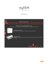
The "App setup mode" helps you to commission radio
components. The required procedure is described in the
wizard of the app.
Views on the myTEM Smart Home App
Under DEMO you can access a demonstration project,
where the functionality of the App is presented.
The star symbolizes the favorites view:
The network icon shows the function view:
The floor plan symbol shows the room view:
© TEM AG; Triststrasse 8; CH – 7007 Chur

Under settings you can change the myTEM App to a
bright background. Example: Bright function view:
Installation of the myTEM Radio Server
CAUTION! Place your device as centrally as possi-
ble in your house or apartment.
CAUTION! When planning your system, take into
account the position of all devices in relation to the
radio range. This is in order to avoid weak signals and
sources of interference wherever possible. Weak,
subdued signals can be caused by furniture, plants
and especially metal objects located between devices.
Possible sources of interference are electrical devices
such as a microwave or computer. In this case, keep
devices at least 50 cm away from the sources of inter-
ference. Ideally, create a sketch to determine the
planned locations of all your devices. Install your
smart home devices with increasing distance to the
myTEM Radio Server.
The default user is: admin, the password: 123
To install your myTEM Radio Server, please proceed
as below:
1. Plug the power supply into a power outlet and
connect it with the USB cable to the device.
2. Connect the device to your external wireless router
with the supplied LAN cable.
CAUTION! To avoid tripping, install your cables
barrier-free and make sure the power outlet and net-
work devices are easily accessible.
CAUTION! If the CAN interface connection is used,
it must be correctly wired (+/–) and the ground be
connected ( to GND). A missing ground connection
can affect the communication.
Wall mounting
The device is most often placed on a horizontal surface, but it is also possible to attach the device to a wall with the en-
closed wall clip. Before you start, please check in which direction you want to lead the connection cables away, i.e.
downwards, upwards or horizontal.
CAUTION! If the cables should lead upwards or downwards, the wall clip must be fastened in both cases with the letter-
ing "TOP" upwards.
CAUTION! If the cables should lead to a side, please ensure that there is sufficient distance to obstacles so that the
device can still be attached to the wall clip.
CAUTION! For wall mounting you also need two dowels with Ø5.0 mm and two screws with flat heads Ø3.0 × 25 mm as
fastening material (not enclosed).
Press the wall clip in the desired orientation/position against the wall and mark the mounting holes. Alternatively, you
can mark two positions vertically or horizontally with a distance of 24 mm.
Drill at the marked positions with Ø5.0 mm, approx. 30 mm deep and then press the dowels completely in.
Attach the wall clip with the two screws.
Plug the device onto the wall clip and slide it until the spring clip clicks into its place.
Connect the cables according to chapter "Installation of the myTEM Radio Server".
Parts of the Radio Server
The LED's show correct power up, working LAN connection and available internet.
The function of the button is described in a separate chapter.
USB type C connection for 5V power supply of the device.
USB type A connector for a WLAN stick or later extensions.
CAN interface connection for optional access to myTEM Smart Home modules.
LAN port for integration of the device into the local LAN network, i.e. to connect onto your router.
Micro SD slot for data recording on a Micro SD card.
The Z-Wave radio antenna is a non-visible, integral part of the device.
Function of the button / Reset to factory default
Press the button briefly to switch on the device from standby.
Press the button for 5 seconds to put the device in standby mode.
Press the button 10x within a short time to reset the device to factory settings. The power LED flashes while the
factory settings are reset and the device restarts.
CAUTION! Devices integrated via Z-Wave must be removed before the reset to factory default so they can be
added to the next /a new wireless network again.
CAUTION! Resetting to factory default deletes all user-defined settings such as user, password, embedded devices,
network configuration, scenes, favorites, etc.
Technical specifications
Dimensions (W × H × D)
88 × 88 × 45 mm
Installation / mounting
On a flat surface or wall mounted
Operating voltage USB supply
110 - 230 VAC ± 10%, 50/60Hz
Operating voltage device
5 VDC ± 5% over USB type C connector
Power consumption in standby
0.3 W
Power consumption in operation
0.8 W (if USB type A connection is not used)
Ambient temperature for operation
0 °C – 50 °C
Ambient temperature for storage
-20 °C – 60 °C
Ambient humidity
5 %RH – 85 %RH (non condensing)
Wire cross-section CAN connector
0.2 mm² – 1.5 mm² / AWG 28 – 16
Stripping length for connector
6.5 mm ± 0.5 mm
Tightening torque for connector
0.2 Nm
Protection class USB supply
II
Overvoltage category USB supply
II
Degree of protection of enclosure
IP 30 (according to EN 60529)
Protection class device
III (according to EN 62368-1)
Overvoltage category device
I (according to EN 62368-1, resp. EN 60664-1)
Pollution degree
2 (according to EN 62368-1)
Electrical safety
EN 62368-1:2014 / AC:2017 EN 62479:2010
EMC main unit
EN 55024:2010 + A1:2015 EN 55032:2015 / AC:2016
EMC radio part
EN 301 489-1 V2.1.1 EN 301 489-3 V2.1.1
Radio spectrum
EN 300 220-2 V3.2.1
RoHS
EN IEC 63000:2018
CE conformity
2014/35/EU (LVD) 2014/53/EU (RED)
2014/30/EU (EMC) 2011/65/EU (RoHS)
Z-Wave hardware platform
ZM5101
Device Type
Gateway
Role Type
Central Static Controller
© TEM AG; Triststrasse 8; CH – 7007 Chur
© TEM AG; Triststrasse 8; CH – 7007 Chur
/