Weslo 8.25 Elliptical User manual
- Type
- User manual
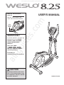
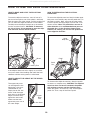
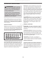
Weslo 8.25 Elliptical is designed to provide an impressive selection of features to make your workouts at home more effective and enjoyable. It comes with a variety of preset programs to help you achieve your fitness goals. The pulse sensor allows you to monitor your heart rate while exercising. Thanks to the water bottle holder you do not need to stop to quench your thirst. Smooth and frictionless operation allows you to work out without disturbing others. Large pedals provide comfort and stability during even the most intense workouts.
With a sturdy and durable build, the Weslo 8.25 Elliptical is made to last. It can support users up to 250 lbs. (113 kg). Its space-saving design makes it a great fit for smaller homes or apartments. The elliptical also features transport wheels that allow for easy relocation.


-
 1
1
-
 2
2
-
 3
3
-
 4
4
-
 5
5
-
 6
6
-
 7
7
-
 8
8
-
 9
9
-
 10
10
-
 11
11
-
 12
12
-
 13
13
-
 14
14
-
 15
15
-
 16
16
-
 17
17
-
 18
18
-
 19
19
-
 20
20


Weslo 8.25 Elliptical User manual
- Type
- User manual
Weslo 8.25 Elliptical is designed to provide an impressive selection of features to make your workouts at home more effective and enjoyable. It comes with a variety of preset programs to help you achieve your fitness goals. The pulse sensor allows you to monitor your heart rate while exercising. Thanks to the water bottle holder you do not need to stop to quench your thirst. Smooth and frictionless operation allows you to work out without disturbing others. Large pedals provide comfort and stability during even the most intense workouts.
With a sturdy and durable build, the Weslo 8.25 Elliptical is made to last. It can support users up to 250 lbs. (113 kg). Its space-saving design makes it a great fit for smaller homes or apartments. The elliptical also features transport wheels that allow for easy relocation.
Ask a question and I''ll find the answer in the document
Finding information in a document is now easier with AI
Related papers
-
Weslo Momentum 635 Elliptical User manual
-
-
-
-
-
-
-
Pro-Form WLCCEX31910.0 User manual
-
-
Other documents
-
ProForm 450 User manual
-
-
-
-
-
NordicTrack E11.0 Elliptical User manual
-
 Image IMEL2105.1 User manual
-
-
-
