
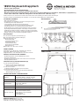
SICHERHEITSHINWEISE
TECHNISCHE DATEN / SPEZIFIKATIONEN
Vielen Dank, dass Sie sich für dieses Produkt entschieden haben. Diese Anleitung informiert Sie über alle wichtigen
Schritte bei Aufbau und Handhabung. Wir empfehlen, sie auch für den späteren Gebrauch aufzubewahren.
KÖNIG & MEYER GmbH & Co. KG
Kiesweg 2, 97877 Wertheim, www.k-m.de
18950-017-55 Rev.01 03-80-312-00 2/17
- Max. Belastbarkeit 80 kg.
- Auf geeigneten, d.h. tragfähigen und ebenen Untergrund achten.
- Vor Aufbringen des Keyboards müssen:
- a. die Standbeine auf gleiche Höhe eingestellt und
- b. die Klappscharniere bis zum Anschlag durchgedrückt sein 5
- Verstellung der Höhe nur in unbelastetem Zustand erlaubt.
- Die Möglichkeit das Produkt zusammenzuklappen und zu verstellen,
- birgt naturgemäß Einklemmgefahren. Umsichtige und aufmerksame
- Handhabung bei Aufbau, Betrieb und Abbau sind daher unverzichtbar.
- Das Instrument sitzt am sichersten auf den rutschhemmenden Gummi-
- auflagen, welche je nach Instrument aufgeklebt werden 8
BESTANDTEILE
A vormontierter Klapptisch (siehe Anleitung 1)
B 4 U-Profil-Füße 3.a (= Höhenverstellungen)
C Zubehörbeutel mit je 4x:
C - Abdeckkappen 2.b,
C - Sechskantschrauben 3.b.1,
C - Flügelmuttern 3.b.2,
C - Sechskantmuttern 4.a.1,
C - Boden-Stellschrauben 4.a.2
C - Auflagegummis 8
D Karton B x T x H: 655 x 455 x 130 mm
ABMESSUNGEN
Ablagefläche Tisch: Breite: 650 - 1040 mm; Tiefe: 394 mm
Höhe: 600 - 1000 mm (10 Stufen, siehe 3, 6, 7)
Platzbedarf (B x T): min. 790 x 460 mm / max. 920 x 510 mm
PRÜFEN, INSTANDHALTEN, REINIGEN
- Bei Wartungsarbeiten auf evtl. Gefährdungen achten
- (Anstoßen, Einklemmen)
- Zur Reinigung ein leicht feuchtes Tuch und ein nicht scheuerndes
- Reinigungsmittel benutzen.
FEHLERSUCHE (F) UND BESEITIGUNG (B)
F: Stativ wackelt auf dem Boden
F: B: Prüfen ob Füße gleich eingestellt sind,
F: B: Stellschrauben justieren, Boden prüfen.
F: Stativ in sich instabil
F: B: Klemmschrauben der Teleskoprohre festziehen
F: Keyboard wackelt auf Stativ
F: B: Unterseite des Keyboards auf Unebenheiten überprüfen,
F: B: Gummiauflagen positionieren.
18950 Keyboard-Klapptisch
- Äußerst stabil und flexibel
- Zusammenlegbar für den mobilen Einsatz
- Mit Stellschrauben zum Ausgleich von Bodenunebenheiten
- Mit zahlreichen Erweiterungsmöglichkeiten: Aufsatz für 2.Keyboard, Mikrofonarm, Notenhalter, Tablet-Halter, Laptophalterung
- Techn. Daten: Höhe: 600 - 1000 mm, Auflagentiefe: 394 mm, Breite: 650 - 1040 mm, 9,6 kg
Material
Stahlrohre/-streben - schwarz pulverbeschichtet
Schrauben, Muttern - verzinkt, vernickelt
Stellschrauben, Gummiauflagen - PA
Traglast max. 80 kg
Abmessungen
Breite: 650 - 1040 mm
Höhe: 600 - 1000 mm
Tiefe: 394 mm
Gewicht 9,6 kg
Karton 655 x 455 x 130 mm, Bruttogewicht: 10,8 kg
Zubehör (optional)
18815 Laptophalterung
18817 Universalhalter (Tablet)
18818 Noten- und Konzepthalter
18952 Aufsatz
18956 Mikrofonarm
A
B
C
D
BESTANDTEILE
ABMESSUNGEN

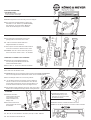
1 AUSGANGSLAGE
1 Gestell auf den Boden stellen,
1 sodass die Füße oben liegen
AUFSTELLANLEITUNG
2 VORBEREITUNG
2.a Beide Fußgestelle bis zum Anschlag nach oben klappen
2.b Die nach hinten verlaufenden Rohre dienen zur
2.b Aufnahme von div. "Zubehör" (s.TECHN.DATEN).
2.b Wir empfehlen, die nicht benutzen Öffnungen
2.b der Rohre mit den Kappen zu verschließen.
3 MONTAGE der U-PROFILFÜSSE
3.a U-Profil-Fuß mit offenem Ende voran in das
3.a jeweilige Fußrohr eintauchen lassen und...
3.b ...mittels Sechskantschraube 3.b.1 und
3.b Flügelmutter 3.b.2 verschrauben.
3.c Der Kopf der Schraube 3.b.1 muss dabei verdreh-
3.c sicher im Sechskant des äußeren Rohres sitzen.
3.d HINWEIS: alle vier U-Profile sind in der gleichen
3.d Höhe zu montieren. Dazu Löcher 1.-10. abzählen.
4 MONTAGE der BODEN-STELLSCHRAUBE
4.a Zunächst die Sechskantmuttern 4.a.1 bis
4.a zum Anschlag auf die Gewinde der Boden-
4.a Stellschrauben 4.a.2 drehen.
4.b Diese dann ca. 15 mm tief in die Füße eindrehen.
5 FUSSGESTELL SICHERN - KLAPPSCHARNIER BETÄTIGEN
5 Das Stativ nun auf die Füße stellen
5.a WARNUNG: Am nicht eingerasteten Klappscharnier besteht QUETSCHGEFAHR!
5.a Fassen Sie Klappscharniere deshalb stets außen an den Schutzbügeln an.
5.b Die Schutzbügel werden nun nach innen gedrückt...
5.c ...bis die Klappscharniere eingerastet sind. Anschließend
5.c machen Sie eine Probe um sicherzustellen, dass die Fuß-
5.c gestelle wirklich eingerastet sind: d.h. die Füße dürfen sich
5.c in diesem Zustand nicht mehr nach innen klappen lassen.
5.d Um die Füße wieder einklappen zu können, muss zuvor durch
5.d Ziehen am Schutzbügel das Klappscharnier entriegelt werden.
6 BODEN-STELLSCHRAUBE
6 JUSTIEREN
6.a Zunächst die Boden-
6.a Stellschrauben der Reihe
6.a nach justieren, bis das
6.a Stativ wackelfrei in der
6.a Waage steht.
6.b Diesen Zustand sichern
6.b durch Anziehen der unteren
6.b Kontermutter.
8 GUMMIAUFLAGEN AUFKLEBEN
8 Schutzpapier abziehen und
8 Gummiauflagen (4x) je nach
8 Instrument an passende Stellen
8 des Rahmens kleben.
9 BREITE EINSTELLEN
9.a Rändelschrauben unterhalb der Querrohre lösen
9.b Gewünschte Breite einstellen, Schrauben wieder festziehen
7 HÖHE EINSTELLEN
7.a - über die vier U-Profil-Füße in 10 Stufen (siehe 3) von 600 - 1000 mm
6.a
7.b - über die Boden-Stellschrauben 6

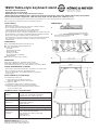
SAFETY NOTES
TECHNICAL DATA / SPECIFICATIONS
Thank you for choosing this product. The instructions provide directions to all of the important set up and handling steps.
We recommend you keep these instructions for future reference.
KÖNIG & MEYER GmbH & Co. KG
Kiesweg 2, 97877 Wertheim, www.k-m.de
18950-017-55 Rev.01 03-80-312-00 2/17
- Maximum Load 80 kg.
- Be sure that the surface will bear the load and is suitable and level.
- Prior to attaching the keyboard ensure that:
- a. the stand legs are adjusted to the same height and that
- b. the folding struts are extended as far as they will go 5
- The fact that the product is collapsible and adjustable can result in the risk of
- pinching/wedging of your fingers. Careful and attentive handling and setup
- during setup, operation and disassembly is indispensable.
- The instrument is most secure when it is placed on the slip-resistant rubber
- caps, which can be adhered to the table according to the instrument’s
- requirements 8
COMPONENTS
A Pre-assembled folding table (see Instructions 1)
B 4 U-Profile-Feet 3.a (= Height adjustments)
C Accessory bag with 4x:
C - Caps 2.b,
C - Hexagonal screws 3.b.1,
C - Wing nuts 3.b.2,
C - Hexagon nuts 4.a.1,
C - Floor adjustment screws 4.a.2
C - Rubber pads 8
D Box W x D x H: 655 x 455 x 130 mm
DIMENSIONS
Table surface: Width: 650 - 1040 mm, depth: 394 mm
Height: 600 - 1000 mm (10 positions, see sections 3, 6, 7)
Space requirements (W x D): min. 790 x 460 mm / max. 920 x 510 mm
CHECK, MAINTENANCE, CLEANING
- In the event of workstation maintenance pay attention to possible risks
- (Risk of bumping into the table, Wedging/Pinching)
- To care for the product, use a damp cloth and a non-abrasive
- cleaning agent.
FAULT-FINDING (F) and REPAIR (R)
F: Stand wobbles on the floor
F: R: Check if the legs are adjusted properly,
F: R: ddjust the adjustment screws, check surface.
F: Stand is not stable
F: R: Tighten the clamp screws on the telescope tube
F: Keyboard is not firmly placed on the stand (unstable)
F: R: Check the bottom of the keyboard for uneven surfaces,
F: R: position the rubber caps.
18950 Table-style keyboard stand
- Extremely stable and flexible
- Collapsible for use on the road
- With adjustment screws to adjust for uneven surfaces
- With a wide array of additional uses: Stacker for 2 keyboard, boom arm, sheet music holder, tablet holder, laptop holder
-Technical Information: Height: 600 - 1000 mm, Table depth: 394 mm, Width: 650 - 1040 mm, 9.6 kg
Material
Steel tubes/-struts - black powder coated
Screws, nuts - galvanized, nickel plated
Adjustment screws, rubber caps - PA
Load max. 80 kg
Dimensions
Width: 650 - 1040 mm
Height: 600 - 1000 mm
Depth: 394 mm
Weight 9.6 kg
Box 655 x 455 x 130 mm, Gross weight: 10.8 kg
Accessories
(optional)
18815 Laptop holder
18817 Universal holder (Ttablet)
18818 Sheet music and concept holder
18952 Stacker
18956 Boom arm
A
B
C
D
COMPONENTS
DIMENSIONS

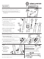
1 INITIAL SITUATION
1 Place the frame on the floor,
1 with the legs facing upwards
SETUP INSTRUCTIONS
2 PREPARATION
2.a Place the folding legs in an upright position as far as they go
2.b The tubes that run towards the back of the table are used to attach
2.b K&M’s various accessories (see Technical Information). We
2.b recommend, that the ends of the tubes that are not being used be
2.b covered with caps.
3 ASSEMBLY the U-PROFILE FEET
3.a Place the U-profile foot - leading with the open end
3.a into the respective foot tube and screw it together...
3.b ...using the hexagon screw 3.b.1
3.b and the wing nut 3.b.2.
3.c The head of the screw 3.b.1 must be securely
3.c placed in the hexagon of the outer tube.
3.d NOTE: all four U-profiles are to be assembled
3.d in the same manner. Count the drill holes 1-10.
4 MOUNT the FLOOR ADJUSTMENT SCREW
4.a First turn the hexagon nut 4.a.1 as
4.a far as it will go into the thread of
4.a the floor adjustment screw 4.a.2.
4.b Then place this approx. 15 mm into the feet.
5 SECURE FOOT FRAME - USING THE FOLDING STRUTS
5 The stand is now placed on its legs
5.a NOTE: If the folding table struts are not properly set there is a
5.a RISK OF WEDGING/PINCHING!
5.a Be sure to only touch the safety guards of the folding table struts.
5.b The safety guards are then pressed inwards...
5.c ...until the folding table struts click into place. Then test to ensure
5.c that the folding table struts are properly clicked into place.
5.c The legs should not fold inwards.
5.d To be able to return the legs to the original position pull on the
5.d safety guard of the folding table struts until they have been released.
6 FLOOR ADJUSTMENT
6 SCREW
6.a First adjust the floor
6.a adjustment screws one
6.a after the other to ensure
6.a that the stand is stable
6.a and balanced.
6.b Secure this position
6.b by tightening the
6.b lower counter nuts.
8 ADHERE THE RUBBER PADS
8 Remove the protective paper and
8 adhere the rubber pads (4x) to the
8 frame according to instrument
8 requirements.
9 WIDTH ADJUSTMENT
9.a Loosen the knurled screws below the vertical tube
9.b Set the desired width and tighten the knurled screws
7 HEIGHT ADJUSTMENT
7.a - via the 4 U-Profile-Feet in 10 positions (see section 3) from 600 - 1000 mm
6.a
7.b - via the floor adjustment screws 6
-
 1
1
-
 2
2
-
 3
3
-
 4
4


K&M 18950 Operating instructions
- Type
- Operating instructions
- This manual is also suitable for
Ask a question and I''ll find the answer in the document
Finding information in a document is now easier with AI
in other languages
- Deutsch: K&M 18950 Bedienungsanleitung
Related papers
Other documents
-
König CMP-KBSLIM10SC Datasheet
-
-
König & Meyer 21070-300-55 Datasheet
-
Trust 18817 Datasheet
-
 OUT MEYER User manual
-
-
-
-
-
