Page is loading ...

Evaluation Board User Guide
UG-369
One Technology Way • P. O. Box 9106 • Norwood, MA 02062-9106, U.S.A. • Te l: 781.329.4700 • Fax: 781.461.3113 • www.analog.com
Evaluation Board for the ADF4151 PLL Frequency Synthesizer
PLEASE SEE THE LAST PAGE FOR AN IMPORTANT
WARNING AND LEGAL TERMS AND CONDITIONS.
Rev. A | Page 1 of 24
FEATURES
General-purpose evaluation board for the ADF4151,
including VCO, loop filter, and TCXO
Contains the ADF4151 frequency synthesizer (500 MHz to
3.5 GHz)
Accompanying software allows complete control of
synthesizer functions from a PC
EVALUATION KIT CONTENTS
EVAL-ADF4151EB1Z board
CD that includes
Self-installing software that allows users to control the
board and exercise all functions of the device
Electronic version of the ADF4151 data sheet
Electronic version of the UG-369 user guide
ADDITIONAL EQUIPMENT
PC running Windows XP or more recent version
Power supply
Spectrum analyzer
Oscilloscope (optional)
DOCUMENTS NEEDED
ADF4151 data sheet
REQUIRED SOFTWARE
Analog Devices, Inc., ADF4151 software (Version 2 or higher)
ADIsimPLL
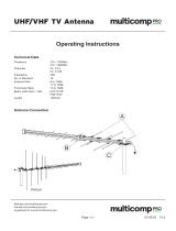
GENERAL DESCRIPTION
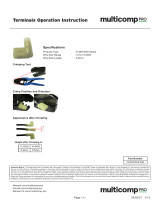
This board is designed to allow the user to evaluate the perfor-
mance of the ADF4151 frequency synthesizer for phase-locked
loops (PLLs). Figure 1 shows the board, which contains the
ADF4151 synthesizer, loop filter, voltage control oscillator
(VCO), reference oscillator (TCXO) of frequency 25 MHz for
the reference input, power supply connectors, and an RF output.
The evaluation kit also contains software that is compatible with
Windows® XP and later versions to allow easy programming of
the synthesizer.
A USB port in the PC is required to program the part.
EVALUATION BOARD
10482-001
Figure 1. EVAL-ADF4151EB1Z

UG-369 Evaluation Board User Guide
Rev. A | Page 2 of 24
TABLE OF CONTENTS
Features .............................................................................................. 1
Evaluation Kit Contents ................................................................... 1
Additional Equipment ..................................................................... 1
Documents Needed .......................................................................... 1
Required Software ............................................................................ 1
General Description ......................................................................... 1
Evaluation Board .............................................................................. 1
Revision History ............................................................................... 2
Quick Start Guide ............................................................................. 3
Evaluation Board Hardware ............................................................ 4
Power Supplies .............................................................................. 4
Input Signals .................................................................................. 4
Output Signals ...............................................................................4
Default Operation Settings ..........................................................4
Additional Options .......................................................................4
Evaluation Board Setup Procedure .................................................5
Software Installation .....................................................................5
Evaluation Board Software ...............................................................9
Evaluation and Test ........................................................................ 12
Evaluation Board Schematics and Artwork ................................ 13
Ordering Information .................................................................... 21
Bill of Materials ........................................................................... 21
Related Links ............................................................................... 22
REVISION HISTORY
2/12—Rev. 0 to Rev. A
Changes to Quick Start Guide Section .......................................... 3
Changes to Power Supply Section .................................................. 4
1/12—Revision 0: Initial Version

Evaluation Board User Guide UG-369
Rev. A | Page 3 of 24
QUICK START GUIDE
Follow these steps to quickly evaluate the ADF4151 device:
1. Install the ADF4151 software.
2. Connect the EVAL-ADF4151EB1Z board to the PC.
3. Follow the hardware driver installation procedure.
4. Connect the power supplies to banana connectors (5.5 V).
5. Run the ADF4151 software.
6. Connect the spectrum analyzer to SMA connector VCO_I/O.
7. Measure the results.

UG-369 Evaluation Board User Guide
Rev. A | Page 4 of 24
EVALUATION BOARD HARDWARE
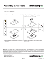
The EVAL-ADF4151EB1Z schematics are shown in Figure 22,
Figure 23, Figure 24, and Figure 25. The silkscreen of the
evaluation board is shown in Figure 2.
POWER SUPPLIES
The board is powered from external banana connectors. The
supplied voltage should be 5.5 V. The power supply circuit uses
high precision, low noise ADP150AUJZ-3.3 linear regulators
and ADP3334ARMZ adjustable LDO regulators to provide 3.3 V
to V
DD
on the board (which supplies the ADF4151 AV
DD
x, DV
DD
,
and SDV
DD
pins) to the ADF4151 V
DD
and 5 V to the ADF4151 V
P
.
INPUT SIGNALS
The reference signal is necessary for proper operation of the
synthesizer. It can be sourced from a provided TCXO or an
external generator, which can be connected to the REFIN edge
mount connector. To use an external reference generator, it is
necessary to remove R1 and R2 to disconnect TCXO from the
reference input and from the supply.
Digital SPI signals are supplied from the Cypress microcontrol-
ler, U6, which is used for communication with the USB port of
the PC.
OUTPUT SIGNALS
All components necessary for LO generation are inserted on
the board. The PLL is made up of the ADF4151 synthesizer, a
fourth-order passive loop filter, and the VCO. The loop filter
must be inserted between the charge pump output and the
VCO input, as shown in Figure 25. If replacing the VCO, a
VCO in a T-package (or similar) must be used. The RF output
is available at the edge mount SMA connector, VCO_I/O.
DEFAULT OPERATION SETTINGS
This board is shipped with a TCXO that provides a reference
frequency of 25 MHz, a fourth-order low-pass filter with
30 kHz bandwidth at I
CP
= 2.25 mA, and a VCO with a 1.7 GHz
to 1.8.GHz frequency range. To test the performance of the part
for a different frequency range and different loop filter, the
relevant components on the board must be changed.
ADDITIONAL OPTIONS
The VVCO connector can be used as a test point to measure the
supply voltage of the VCO in its default configuration. It can
also be used to provide an external supply for the on-board VCO;
however, if an external supply for VCO is used, Resistor R31
must be removed to disconnect the connector from the output
of the on-board voltage regulator.
Optionally, an external VCO can be used. In this case, it is
necessary to remove R29 and insert a 0 Ω link at R46 to form
a connection between the loop filter output and the VTUNE
SMA edge mount connector. Remove R31 to disconnect the
on-board VCO from the power supply. Remove Resistor R26 to
disconnect the output of the on-board VCO from the RF signal
path, and replace Resistors R27 and R28 with 0 Ω links to
ensure operation of the VCO_I/O connector as an input from
an external VCO.
10482-002
Figure 2. Evaluation Board Silkscreen

Evaluation Board User Guide UG-369
Rev. A | Page 5 of 24
EVALUATION BOARD SETUP PROCEDURE
SOFTWARE INSTALLATION
Use the following steps to install the software.
1. Install the Analog Devices ADF4151 software by double-
clicking ADF4151 Setup.msi.
If you are using Windows XP, follow the instructions in the
Windows XP Software Installation Guide section (see
Figure 3 to Figure 7).
If you are using Windows Vista or Windows 7, follow the
instructions in the Windows Vista and Windows 7 Software
Installation Guide section (see Figure 8 to Figure 12).
Note that the software requires Microsoft Windows
Installer and Microsoft .NET Framework 3.5 (or higher).
The installer connects to the Internet and downloads
Microsoft .NET Framework automatically. Alternatively,
before running the ADF4151 Setup.msi, both the installer
and .NET Framework can be installed from the CD that is
provided.
2. Connect your board by USB.
If you are using Windows XP, follow the steps in the
Windows XP Driver Installation Guide section (see Figure 13
to Figure 16).
On Windows Vista or Windows 7, the drivers install
automatically.
Windows XP Software Installation Guide
10482-003
Figure 3. Windows XP ADF4151 Software Installation, Setup Wizard
1. Click Next >.
10482-004
Figure 4. Windows XP ADF4151 Software Installation, Select Installation
Folder
2. Choose an installation directory and click Next >.

UG-369 Evaluation Board User Guide
Rev. A | Page 6 of 24
10482-005
Figure 5. Windows XP ADF4151 Software Installation, Confirm Installation
3. Click Next >.
10482-006
Figure 6. Windows XP ADF4151 Software Installation, Logo Testing
4. Click Continue Anyway.
10482-007
Figure 7. Windows XP ADF4151 Software Installation, Installation Complete
5. Click Close.
Windows Vista and Windows 7 Software Installation Guide
10482-008
Figure 8. Windows Vista/7 ADF4151 Software Installation, Setup Wizard
1. Click Next >.
10482-009
Figure 9. Windows Vista/7 ADF4151 Software Installation, Select Installation
Folder
2. Choose an installation directory and click Next >.

Evaluation Board User Guide UG-369
Rev. A | Page 7 of 24
10482-010
Figure 10. Windows Vista/7 ADF4151 Software Installation, Confirm Installation
3. Click Next >.
10482-011
Figure 11. Windows Vista/7 ADF4151 Software Installation, Start Installation
4. Click Install.
10482-012
Figure 12. Windows Vista/7 ADF4151 Software Installation, Install Complete
5. Click Close.
Windows XP Driver Installation Guide
10482-013
Figure 13. Windows XP USB Driver Installation, Found New Hardware Wizard
1. Choose Yes, this time only and click Next >.
10482-014
Figure 14. Windows XP USB Driver Installation, Install Options
2. Click Next >.
Note that Figure 14 may list Analog Devices RFG.L Eval Board
instead of ADF4xxx USB Adapter Board.

UG-369 Evaluation Board User Guide
Rev. A | Page 8 of 24
10482-015
10482-016
Figure 16. Windows XP USB Driver Installation, Complete Installation
Figure 15. Windows XP USB Driver Installation, Logo Testing
4. Click Finish.
3. Click Continue Anyway.

Evaluation Board User Guide UG-369
Rev. A | Page 9 of 24
EVALUATION BOARD SOFTWARE
The control software for the EVAL-ADF4151EB1Z is available
on the CD included in the evaluation kit. To install the software,
see the Software Installation section.
To run the software, first connect the board to the USB port of
the PC and then click the ADF4151 file on the desktop or in the
Start menu. Confirm that USB OK is displayed at the top right
corner of the software front panel display window (see Figure 17).
Otherwise, the software has no connection to the evaluation board.
Note that, when connecting the board, it takes about 5 sec to
10 sec for the status label to change.
If the software is started before the board is connected to USB
port, an error window opens, informing that the USB device
was not found, and the No USB message is displayed in the top
right corner of the software front panel window. In this case,
connect the board to the USB port and click the Connect USB
button.
10482-017
Figure 17. Software Front Panel Display—Select Device and Connection

UG-369 Evaluation Board User Guide
Rev. A | Page 10 of 24
Use the Frequency text box in the Reference section to set the
correct reference frequency. The default reference on the
software window is at 25 MHz and matches the frequency of the
TCXO present on the board.
Use the VCO Output Frequency section to control the output
frequency. To achieve single-tone on the VCO output, type the
desired output frequency in the Activate f1 text box (in mega-
hertz) and ensure that Stop is selected in the Dynamic section
under VCO Output Frequency. Selecting the Alternate option
causes the frequency on the VCO output to switch between the
Activate f1 and Activate f2 values. The delay time between
frequency switches is controlled by the Approximate Delay
option. The third option of the Dynamic section, Sweep, allows
the output frequency to constantly change with the frequency
step set by Channel Spacing, starting from Activate f1 until it
reaches Activate f2. After the Active f2 frequency is reached,
the sweep is repeated.
Some register settings may need to be set manually. Click the
Register 1 to Register 5 buttons to open the register settings
windows, as shown in Figure 18.
Click the REGISTERS button to display the binary and
hexadecimal values for all registers, as shown in Figure 19.
When a new register setting value is entered (see Figure 18),
the relevant Update Rx (where x = 0 to 5) button becomes red,
indicating that it must be clicked to program the part with the
new value. Clicking the Update ALL button programs all
register values simultaneously.
Click the OK button to confirm the new value in the Register x
Settings (where x = 1, 2, 3, or 5) window (see Figure 18). Click
Update Rx to program the part with the new value. The new
value is retained in the Register x Settings window if it is
opened again.
If the value entered is outside of the range specified in the
ADF4151 data sheet, an error message appears and the field is
automatically updated to the lowest or highest value within the
allowed range. Some limits are changed dynamically based on
the values of other registers; that is, the highest allowed value
for Phase in the Register 1 Settings window depends on the
current value of the modulus (MOD in the Settings section),
which is calculated based on the data from the Reference
section and the Channel Spacing field (under the VCO Output
Frequency section).
Click the Cancel button to abandon a register value change, and
the new value is not retained in the Register x Settings window
if it is opened again.
10482-018
Figure 18. Register Settings Windows for Register 1, Register 2, Register 3, and Register 5

Evaluation Board User Guide UG-369
Rev. A | Page 11 of 24
10482-019
Figure 19. Registers Window for Register 1, Register 2, Register 3, and Register 5

UG-369 Evaluation Board User Guide
Rev. A | Page 12 of 24
EVALUATION AND TEST
To evaluate and test the performance of the ADF4151, use the
following procedure:
1. If using a different VCO and loop filter than provided on
the board, ensure that a VCO and loop filter are properly
inserted on the board. Use ADIsimPLL to generate the
loop filter component values.
2. Install the ADF4151software. Connect the evaluation
board to a PC using the supplied USB cable. Follow the
hardware driver installation procedure that appears.
3. If the on-board crystal oscillator is used, skip this step. If
an external reference is necessary, connect a reference
signal to the REFIN edge mount connector.
4. Connect the power supply to the board.
5. Connect a spectrum analyzer to Connector VCO_I/O.
6. Run the ADF4151 software.
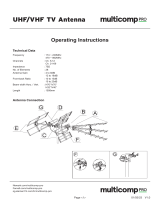
7. In the software window, set the VCO center frequency
(Figure 20 shows a screenshot of a spectrum analyzer taken
at a frequency of 1750 MHz, which is in the middle range
of the provided VCO). Set the PFD frequency as defined in
ADIsimPLL, and program the reference frequency to 25
MHz if the on-board TCXO is used or to the frequency
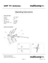
that has been supplied to the REFIN connector. See Figure 21
for the suggested setup.
8. Measure the output spectrum. Figure 20 shows a
1750 MHz output.
Att 5 dB
A
*
1AP
CLRWR
Ref 0 dBm
200 kHz/Center 1.749996795 GHz Span 2 MHz
*
3DB
RBW 20 kHz
VBW 50 kHz
SWT 20 ms
-100
-90
-80
-70
-60
-50
-40
-30
-20
-10
0
1
Marker 1 [T1 ]
-5.28 dBm
1.749996795 GHz
Date: 14.DEC.2011 16:44:31
10482-020
Figure 20. Spectrum Analyzer Display
10482-021
PC
EXTERNAL DC
SUPPLY
EXTERNAL DC
SUPPLY
TCXO
VCO
LOOP FILTER
LOCK
DETECT
LED
PLL
POWER
LED
USB LED
PLL
USB
POWER
SUPPLIES
SIGNAL
GENERATOR
SPECTRUM
ANALYZER
REFERENCE
(OPTIONAL)
C21
C13
C14
R47
R34
C67
R9
R59
Figure 21. Typical Evaluation Setup

Evaluation Board User Guide UG-369
Rev. A | Page 13 of 24
EVALUATION BOARD SCHEMATICS AND ARTWORK
Lock Detect
C1
0.1uF
C2
10pF
C11 1nF
C12 1nF
REFIN
R3
DNI
T2
LD
4
VCC
3
OUT
2
GND
1
GND
Y1
T1
R2
0r
+
C9
DNI
D1
R19
10k
R17
10k
R16
10k
R15
10k
R4
5k1
C3
10pF
C4
0.1uF
R5
DNI
R8 DNI
R7
1k
R6
DNI
R14
0r
R18
DNI
C24
DNI
C25
DNI
L1 DNI
L2
DNI
R13
DNI
C18
DNI
CLK DATALE CE
PDRF
MUXOUT
RFOUT+
RFOUT-
C42
DNI
C43
DNI
AGND
R1
C10
0.1uF
C7
1uF
C16
10pF
4
VCC
3
OUT
2
GND
Y1(ALT)
25MHz
R23 DNI
R24 DNI
C75
1uF
C76
10pF
C19
100pF
C20
100pF
1
CLK
2
DATA
3
LE
4
CE
5
SW
6
VP
7
CPOUT
8
CPGND
9
AGND
10
AVDD1
11
AGND
12
NC
13
NC
14
RFIN+
15
RFIN-
16
AVDD
17
AVDD2
18
AGND
33
PADDLE
21
AGND
22
RSET
32
SDVDD
25
LD
26
DGND
27
DGND
28
DVDD
29
REFIN
30
MUXOUT
31
SDGND
U1
ADF4151
CLK
DATA
LE
VDD
PDRF
MUXOUT
VDD
VDD
CE
VDD
VOUT
VDD
CPOUT
VDD
VP
VDD
FLSW
AGND
RF_IN
AGND
AGND
AGND
AGND
AGND
AGND
10482-022
Figure 22. Evaluation Board Schematic (Page 1)

UG-369 Evaluation Board User Guide
Rev. A | Page 14 of 24
R38
1k
D3
GND
BANANA-BLACK
VSUPPLY_5V5
BANANA-RED
VDD
C31
1uF
C8
1uF
1
VIN
2
GND
3
EN
5
VOUT
U2
ADP150-TSOT
R37
0r
R42
DNI
C28
1uF
R30
1r
R10
DNI
C5
DNI
R64
DNI
+
C22
DNI
R65
DNI
+
C23
DNI
1
OUT
6
SD
5
GND
8
IN
3
FB
4
NC
7
IN
2
OUT
U3
C30
DNI
C32
DNI
C39
1nF
R12
210K
+
C40
22uF
R32
64K9
+
C41
22uF
1
OUT
6
SD
5
GND
8
IN
3
FB
4
NC
7
IN
2
OUT
U4
C64
1uF
C65
1uF
VOUT
C66
1uF
1
VIN
2
GND
3
EN
5
VOUT
U10
ADP150-TSOT
R35
0r
R36
DNI
C77
1uF
R48
0r
R25
DNI
D2
7.5V
BZX84C7V5
D4
VDD
5V_USB
VP
+5V
VOUT
VP
10482-023
Figure 23. Evaluation Board Schematic (Page 2)

Evaluation Board User Guide UG-369
Rev. A | Page 15 of 24
Decoupling for U7 - place one close to each VCC pin
SCREEN BOX
R44
100k
R45
100k
C54
0.1uF
C55
0.1uF
C53
0.1uF
D6
R39
2K2
1
VBUS
2
D-
3
D+
4
IO
5
GND
6
SHLD1
7
SHLD2
8
SHLD3
9
SHLD4
USB
USB-MINI-B
50
PD5/FD13
51
PD6/FD14
52
PD7/FD15
54
CLKOUT
1
RDY0/*SLRD
2
RDY1/*SLWR
4
XTALOUT
5
XTALIN
8
D+
9
D-
13
IFCLK
14
RSVD
15
SCL
16
SDA
18
PB0/FD0
19
PB1/FD1
20
PB2/FD2
21
PB3/FD3
49
PD4/FD12
48
PD3/FD11
47
PD2/FD10
46
PD1/FD9
45
PD0/FD8
44
*WAKEUP
42
RESET
40
PA7/*FLD/SLCS
39
PA6/*PKTEND
38
PA5/FIFOADR1
37
PA4/FIFOADR0
36
PA3/*WU2
35
PA2/*SLOE
34
PA1/INT1
33
PA0/INT0
31
CTL2/*FLAGC
30
CTL1/*FLAGB
29
CTL0/*FLAGA
25
PB7/FD7
24
PB6/FD6
23
PB5/FD5
22
PB4/FD4
3
AVCC
7
VCC
11
VCC
17
VCC
27
VCC
32
VCC
43
VCC
55
VCC
6
AGND
10
GND
12
GND
26
GND
28
GND
41
GND
53
GND
56
GND
U6
CY7C68013-CSP
5V_USB
3V3_USB
C52 10pF
R55
DNI
R57
DNI
R50
2K2
R49
2K2
C57
0.1UF
C56
10pF
1
A0
2
A1
3
A2
4
VSS
8
VCC
7
WP
6
SCL
5
SDA
U7
24LC64
C44
0.1uF
C45
0.1uF
C46
0.1uF
C58
0.1uF
C59
0.1uF
C60
0.1uF
C61
0.1uF
R53
DNI
R56
0r
R51
0r
R52
0r
R54
DNI
R58
0r
C49
1nF
R40
140K
+
C48
22uF
R41
78K7
+
C51
22uF
1
OUT
2
OUT
3
FB
4
NC
5
GND
6
SD
7
IN
8
IN
U5
ADP3334
C47
1uF
C50
1uF
C27
12pF
C26
12pF
Y2
24.0MHz
R43
DNI
3V3-USB
CLK
LE
MUXOUT
DATA
3V3-USB
3V3-USB
3V3-USB
3V3-USB
3V3-USB
3V3-USB
3V3-USB
PDRF
CE
5V_USB
DGND
3V3-USB
AGND
3V3-USB
10482-024
Figure 24. Evaluation Board Schematic (Page 3)

UG-369 Evaluation Board User Guide
Rev. A | Page 16 of 24
R59
120r
C21
6.8nF
C13
120nF
C14
4.7nF
R9
75r
VTUNE
R11
150r
R21
68r
R20
68r
R27
18r
C17
100pF
VCO_I/O
R28
18r
C37
100pF
R33
51r
10
RF
2
VT
14
VCC
Y3
ROS-1800+
C15
10pF
C29
1uF
VVCO
R31
0r
R46
DNI
C6
100pF
R26
18r
R34
75r
C67
4.7nF
1
RFIN
2
GND
3
GND
4
CB
8
RFOUT
7
GND
6
GND
5
VPOS
U8
ADL5541
C68
33pF
C69
33pF
C70
1uF
L3
47nH
C71
68pF
C72
1.2nF
C73
1uF
C74 68pF
R47
DNI
R22
DNI
R60
DNI
R61
0r
R29
0r
RF_IN
CPOUT
+5V
+5V
FLSW
+5V
AGND
10482-025
Figure 25. Evaluation Board Schematic (Page 4)

Evaluation Board User Guide UG-369
Rev. A | Page 17 of 24
10482-026
Figure 26. Layer 1 (Component Side)

UG-369 Evaluation Board User Guide
Rev. A | Page 18 of 24
10482-027
Figure 27. Layer 2 (Ground Plane)

Evaluation Board User Guide UG-369
Rev. A | Page 19 of 24
10482-028
Figure 28. Layer 3 (Power Plane)

UG-369 Evaluation Board User Guide
Rev. A | Page 20 of 24
10482-029
Figure 29. Layer 4 (Solder Side)
/