Follett Symphony 50HI400A User manual
- Category
- Ice cube makers
- Type
- User manual

Installation, Operation and Service Manual
© Follett Corporation
00187153R01
Following installation, please forward this manual
to the appropriate operations person.
801 Church Lane • Easton, PA 18040, USA
Toll free (800) 523-9361 • (610) 252-7301
Fax (610) 250-0696 • www.follettice.com
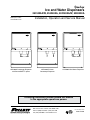
Ice and Water Dispensers
25CI400A/W, 25HI400A, 50CI400A/W, 50HI400A
Order parts online
www.follettice.com
25CI400A Countertop Dispenser
with SensorSAFE™ option
25HI400A Wall Mount Dispenser25CI400A/W Lever
Countertop Dispenser

2 25CI400A/W • 25HI400A • 50CI400A/W • 50HI400A
Follett Corporation Equipment Return Policy
Follett equipment may be returned for credit under the following conditions:
1. The equipment is new and unused.
2. A return authorization number has been issued by customer service within 30 days after shipment.
3. Follett receives the equipment at the factory in Easton, PA within 30 days after issuance of the return authorization number.
4. The equipment must be returned in Follett packaging. If the packaging has been damaged or discarded, Follett will forward, at the customer’s expense, new
packaging.
Note: Return freight charges are the responsibility of the customer. If equipment is returned and is damaged because of improper packaging, Follett Corporation
will not be held responsible.
Credit will be issued when: The equipment has been inspected by Follett and deemed suitable to be returned to stock.
Note: A 15% restocking charge will be deducted from the credit. If the cost to return the product to stock exceeds 15%, the actual cost will be deducted.
Contents
Welcome to Follett .................................. 3
Before you begin ............................... 3
Contact Information ............................. 3
Specications ..................................... 4
Electrical ..................................... 5
Ambient ...................................... 5
Plumbing ..................................... 5
Ventilation and service clearances ................. 5
Uncrated weight ................................ 5
Installation ........................................ 6
Before you begin ............................... 6
Installing countertop dispensers with
rear exiting utilities (no legs) ...................... 6
Installing countertop dispensers with
bottom exiting utilities ............................ 6
Installing wall mount dispensers ................... 8
Icemaker cleaning & sanitizing ........................10
Quarterly air lter cleaning ........................10
Semi-annual icemaker cleaning & sanitizing ..........10
Cleaning solution ...............................10
Sanitizing solution ..............................10
Start-up following cleaning ........................11
Dispenser cleaning & sanitizing .......................12
Cleaning solution ...............................12
Sanitizing solution ..............................12
Daily cleaning ..................................12
Weekly cleaning ................................12
Cleaning SensorSAFE lens .......................12
Semi-annual cleaning and sanitizing
of dispenser hopper .............................12
Service ..........................................13
Icemaker operation .............................13
The icemaking process ......................13
Ice harvest system diagram ...................13
Disassembly and replacement instructions ...........14
Dispense wheel removal and installation .........14
Drive bar removal ...........................14
Wheel motor assembly removal ................14
Ice transport tube replacement ................14
Icemaker removal ...............................15
Evaporator disassembly ......................18
Evaporator reassembly .......................18
Gearmotor replacement ......................19
Fan removal ...............................19
Electrical systems ................................. 20
Electrical component locations ................... 20
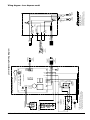
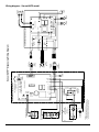
Wiring diagram - lever dispense model ............. 21
Wiring diagram - SensorSAFE model .............. 22
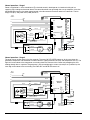
Icemaker operational and diagnostic sequences ......... 23
Circuitry notes ............................. 23
Normal operation – Stage 1 .................. 24
Normal operation – Stage 2 .................. 24
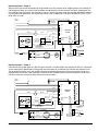
Normal operation – Stage 3 .................. 25
Normal operation – Stage 4 .................. 25
Normal operation – Stage 5 .................. 26
Normal operation – Stage 6 .................. 26
Diagnostic sequence – Stage 7 ............... 27
Diagnostic sequence – Stage 8 ............... 27
Diagnostic sequence – Stage 9 ............... 28
Diagnostic sequence – Stage 10 .............. 28
Refrigeration cycle ......................... 29
Refrigeration data ............................. 30
Ice production ............................. 30
Ice capacity test ........................... 30
Compressor current draw .................... 30
Gearmotor data ........................... 30
Refrigeration system ........................ 30
Icemaker charge specications ............... 30
Refrigerant replacement requirements .......... 30
Evacuation ............................... 30
Ambients ................................. 30
Dispenser troubleshooting .......................... 31
Before calling for service ........................ 31
Lever model troubleshooting guide ................ 31
SensorSAFE model troubleshooting guide .......... 31
Board guide .............................. 31
Lens/sensor troubleshooting ................. 31
Icemaker troubleshooting ........................... 32
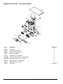
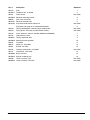
Dispenser replacement parts ........................ 34
Dispenser exterior ............................. 34
Dispense chute and splash panel areas –
lever models .................................. 35
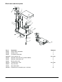
Dispenser electrical box – lever models ............ 36
Dispense chute and splash panel areas –
SensorSAFE models ........................... 37
Dispenser electrical box – SensorSAFE models ...... 38
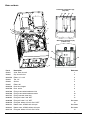
Wheel motor and drive system ................... 39
Water and drain ............................... 40
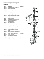
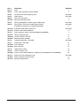
Icemaker replacement parts ......................... 41
Evaporator ................................... 41
Air-cooled icemakers ........................... 42
Water-cooled icemakers ......................... 44
Icemaker electrical components .................. 46

25CI400A/W • 25HI400A • 50CI400A/W • 50HI400A 3
Welcome to Follett
Follett equipment enjoys a well-deserved reputation for excellent performance, long-term reliability and outstanding
after-the-sale support. To ensure that this equipment delivers that same degree of service, we ask that you take a
moment to review the installation portion of this manual before beginning to install the unit. Our installation instructions
are designed to help you achieve a trouble-free installation. Should you have any questions or require technical help at
any point, please call our technical service group at (800) 523-9361 or (610) 252-7301.
Note: To expedite assistance, all correspondence or communication MUST include the model number, serial number
and complete and detailed explanation of the problem
Before you begin
After uncrating and removing all packing material, inspect the equipment for concealed shipping damage. If damage
is found, notify the shipper immediately and contact Follett Corporation so that we can help in the ling of a claim, if
necessary.
Check your paperwork to determine which model you have. Follett model numbers are designed to provide information
about the type and capacity of Follett ice dispensing equipment. Following is an explanation of the different model
numbers.
IMPORTANT
• Onlyqualiedtechniciansshouldattempttoserviceormaintainthisiceandwaterdispenser
• Noserviceormaintenanceshouldbeundertakenuntilthetechnicianhasthoroughlyreadthis
servicemanual
Contact Information
FOLLETT CORPORATION, 801 Church Lane, Easton, PA 18040 USA
Phone: 800-523-9361
Fax: 610-250-0696
Web site: www.follettice.com
25CI400A
Condenser type, A = air-cooled, W= water-cooled
Icemaker capacity in lbs per day
Icemaker location, I = integral (behind front splash panel)
Dispenser conguration, C = countertop, H = wall mount
Approximate storage capacity in lbs (25 or 50)
CAUTION
• Donottiltanyunitfurtherthan30°offverticalduringuncratingorinstallation
• Dispenserbinareacontainsmechanical,movingparts.Keephandsandarmsclearofthisareaatalltimes.Ifaccesstothisarea
isrequired,powertounitmustbedisconnectedrst.
• Iceisslippery.Besurecountersandoorsarounddispenserareclean,dryandfreeofice.
• Donotblockleftsideairintakeorrightsideairexhaust
IMPORTANT NOTICE
• FollettrecommendsaFollettQC4-FL4Swaterltersystem(item#00130229)beinstalledintheicemakerinletwaterline
• Priortooperationcleanandsanitizethedispenserinaccordancewithinstructionsfoundinthismanual

4 25CI400A/W • 25HI400A • 50CI400A/W • 50HI400A
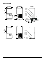
Specications
25CI400A/W
36"
(915mm)
50CI400A/W
40"
(1016mm)
21" (534mm)
Front View
Countertop
Wall mount
Right Side ViewRear View
Front View Right Side ViewRear View
24" (610mm)
23"
(585mm)
10.5"
(267mm)
14.25"
(362mm)
25HI400A/W
36"
(915mm)
50HI400A/W
40"
(1016mm)
21" (534mm) 24" (610mm)
14.25"
(362mm)
2" (52mm)
plumbing
connection
knockout
3/4" FPT
drain
Condenser
outlet (water-
cooled only)
Condenser
inlet (water-
cooled only)
3/8" water
inlet
5.18" (132mm)
6.8"
(173mm)
7' (2.1m)
power cord
w/5-20 90°
hospital-grade
plug
10.5"
(267mm)
8.25" (210mm)
2.5"
(64mm)
2" (52mm)
plumbing
connection
knockout
3/4" FPT
drain
3/8" water
inlet
6.8"
(173mm)
7' (2.1m)
power cord
w/5-20 90°
hospital-grade
plug
10.5"
(267mm)
AIR INTAKE
AIR EXHAUST
AIR INTAKE
AIR EXHAUST

25CI400A/W • 25HI400A • 50CI400A/W • 50HI400A 5
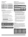
Electrical
115V, 60Hz, 1 phase, 14.0 amps. Connect to dedicated 20 amp circuit, fuse or breaker.
Note: It is preferred that circuit be protected by a GFCI.
Furnished with 7 ft (2m) power cord with a 90° NEMA hospital grade 5-20 plug.
Ambient
Maximum Minimum
Air temp 100 F/38 C (Best performance below 80 F/27 C) 50 F/10 C
Water temp 90 F/32 C (Best performance below 70 F/21 C) 40 F/4 C
Water pressure 70 P.S.I. 10 P.S.I.
Plumbing
Connections – 25/50CI400A/W Rough-ins–25/50HI400A/
Dispenser drain All – 3/4" FNPT Air-cooled – 3/4" FNPT
Water inlet All – 3/8" FNPT All – 1/2" FNPT
Condenser inlet Water-cooled – 3/8" FNPT N/A
Condenser outlet Water-cooled – 3/8" FNPT N/A
Note: Water shut-off recommended within 10 feet (3m) of dispenser. Drain to be hard-piped
and insulated. Maintain at least 1/4" per foot (20mm per 1m run) of slope on horizontal runs.
CAUTION
• Donotblockleftsideairintakeorrightsideairexhaust
Ventilationandserviceclearances
Air-cooled Water-cooled
Requiredforventilation 3" (77mm) each side N/A
Suggestedforservice 12" (305mm) top,
6"(153mm) left side
12" (305mm) top
Uncrated weight
25/50CI400A/W (countertop) 215 lbs (98kg)
25/50HI400A (wall mount) 230 lbs (105kg)

6 25CI400A/W • 25HI400A • 50CI400A/W • 50HI400A
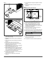
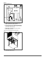
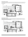
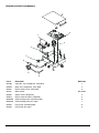
Fig. 2
Utilityconnectionsasviewed
fromtopforcountertopbackaccess
3/8"
diameter cord
condenser inlet
3/8" FNPT
drain plug
condenser outlet
3/8" FNPT
drain
3/4" FNPT
potable water
3/8" FNPT
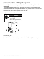
6. Make utility connections (Fig. 2).
CAUTION
• Donotconnectwater-cooledcondenseroutletlineto
the dispenser drain line.
7. Turn on water supply and check for leaks.
8. Clean and sanitize dispenser and icemaker before
putting into service.
9. Turn power on and allow icemaker to produce ice.
Installing countertop dispensers with
bottomexitingutilities
WARNING
• Asturdyworksurfacecapableofsupportingtheentire
dispenser must be used
• Theworksurfacemustbelargeenoughtoaccommodate
height of dispenser
• Failuretoprovidepropersupportmayresultinpersonal
injury
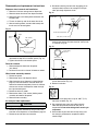
Fig.3
5.00"
(127mm)
min.
1. Position dispenser with dispense chutes facing
upward on sturdy work surface (Fig. 3).
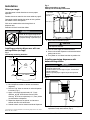
Installation
Before you begin
Level dispenser in both directions to ensure proper
operation.
Provide clearances noted in clearances table on page 5.
Countertop models provide the option of taking utilities
out bottom or back of dispenser.
Wall mount model utilities exit through back of
dispenser only.
Directions for each installation follow.
WARNING
• DONOTLIFTUNITATTHESEPOINTS.
Panels will not support weight of unit
• Failuretofollowwarningmayresultin
equipment damage or personal injury
Installing countertop dispensers with rear
exitingutilities(nolegs)
Fig.1
Countertop anchoring locations
12.50"
(318mm)
1.56"
(40mm)
20" (508mm)
.50"
(13mm)
4X
Ø.375"
(10mm)
hole
1. Position dispenser in desired location.
2. Mark dispenser outline on counter and remove
dispenser.
3. Drill four 7/16" holes in counter to anchor dispenser
to counter (Fig. 1).
4. Apply a thick bead approximately 1/4" (7mm)
diameter of NSF listed silicone sealant (Dow
Corning*
1
RTV-732 or equivalent) 1/4" (7mm) inside
marked outline of dispenser.
5. Reposition dispenser on counter and secure to
counter with four 3/8"-16NC bolts.
6. Smooth excess sealant around outside of dispenser.
* Dow Corning is a register trademark of Dow Corning Corporation in the United
States and other countries

25CI400A/W • 25HI400A • 50CI400A/W • 50HI400A 7
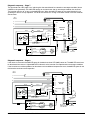
12. Raise the dispenser upright and position in desired
location.
13. Mark dispenser outline on counter and remove
dispenser.
Fig. 6
Countertopcutoutviewedfromtop
16.00"
(407mm)
3.13"
(80mm)
12.50"
(318mm)
1.56"
(40mm)
14"
(356mm)
20"
(508mm)
.50"
(13mm)
4X
Ø.375"
(10mm)
hole
Cutout
connections
through
bottom
13. Cut countertop utility opening and drill four 7/16"
holes to anchor dispenser to counter (Fig. 6).
12. Apply a thick bead approximately 1/4" (7mm)
diameter of NSF listed silicone sealant (Dow
Corning* RTV-732 or equivalent) 1/4" (7mm) inside
marked outline of dispenser.
13. Reposition dispenser on counter and secure to
counter with four 3/8"-16NC bolts.
12. Smooth excess sealant around outside of dispenser.
13. Make utility connections through countertop cutout.
CAUTION
• Donotconnectwater-cooledcondenseroutletlineto
the dispenser drain line.
14. Turn on water supply and check for leaks.
15. Clean and sanitize dispenser and ice machine
before putting into service.
16. Turn power on and allow icemaker to produce ice.
Fig. 4
4.1
4.2
4.3
4.4
Fig. 5
5.1
5.2
5.3
5.4
2. Disconnect the internal water line from the potable
water connection tting.
3. Remove tting from the back wall of the dispenser
(Fig. 4.1).
4. Relocate tting to internal bulkhead and reconnect
(Fig. 5.1).
6. Remove power cord strain relief (Fig. 4.2).
7. Relocate the cord and strain relief to the internal
bulkhead and reconnect (Fig. 5.2).
8. Water-cooledonly. Disconnect internal condenser
water inlet and outlet ttings (Fig. 4.3).
9. Water-cooledonly. Relocate water inlet and outlet
ttings and reconnect (Fig. 5.3). Note: The water
inlet is connected to the condenser; the outlet line is
connected to the water regulating valve.
10. Remove the drain plug from the internal drain line
connection point (Fig. 5.4).
11. Relocate to back of dispenser and reconnect
(Fig. 4.4).

8 25CI400A/W • 25HI400A • 50CI400A/W • 50HI400A
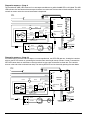
Fig.9
9.1
9.3
9.2
9.4
1. Using Fig. 8 as a guide, locate wall bracket
mounting position relative to wall studs.
2. Install the supplied wall bracket with six 3/8"
diameter fasteners (Fig. 9.1).
Note: Three holes are available at each fastening
site to allow capture of studs or supports within the
wall.
2. Locate and cut utility hole in wall using Fig. 8
dimensions (9.2).
3. Rough in utilities. Wall mount bracket dimensions
(Fig. 8) can be used as a template.
Water: 1/2" FNPT
Drain: 3/4" FNPT
4. Lift dispenser onto wall bracket positioning unit so
that hook on back of dispenser is captured by wall
bracket support angle (Fig. 9.3).
5. Install two 1/4" X 20 screws through bottom of wall
bracket into bottom of dispenser to secure dispenser
to wall bracket (Fig. 9.4).
6. Install supplied 1/2" MPT X 3/8" push-in adapter
onto 1/2" FNPT water supply.
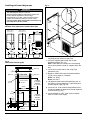
Installing wall mount dispensers
WARNING
• Wallmountdispensersareintendedtobemountedabovea
sink,eliminatingtheneedforadrainpan.
• Beforebeginninginstallationverifythatthesinksizeand
location meet the requirements shown in Fig. 7.
• Ifrequirementsarenotmet,adrainpanmustbeusedto
preventiceandwaterfromfallingoncounteroroor.
• FAILURETOTAKETHESEPRECAUTIONSCOULDRESULTIN
SLIPSANDFALLSONWETFLOORS
Fig. 7
Minimumsinkrequirements(withoutdrainpan)
17"
(432mm)
24.5"
(623mm)
Side View
14.25"
(362mm)
18"
(458mm)
23"
(585mm) min.
50HI
58.5"
(1486mm)
25HI
54.5"
(1385mm)
Front View
Minimum Sink Requirements
(shown without drain pan)
21.5"
(547mm)
Front View
21.5"
(547mm)
23"
(585mm) min.
Sink centered
below dispenser
14.25"
(362mm) min.
Sink centered
below chutes
Fig. 8
Wallbracketlocationguide
.75"
(20mm)
50HI400A
15" (381mm)
25HI400A
13" (330mm)
50HI400A
21" (483mm)
25HI400A
19" (483mm)
16.00"
(406 mm)
0.438" (11mm)
clearance
6"
(153mm)
Wall studWall stud
Wall stud
Top view
Front view
Utility
cut-out
3.4"
(87mm)
4.12"
(105mm)
7"
(178mm)
1"
(26mm)
2.44"
(62mm)
3.50"
(89mm)
1"
(26mm)
(anchor
points)

25CI400A/W • 25HI400A • 50CI400A/W • 50HI400A 9
Fig.10
Dispenserbottomview
10.1
10.3
10.2
7. Connect supplied 3/8" water line between water
supply and water inlet fitting (Fig. 10.1).
8. Using supplied 3/4" drain tubing and barbed fittings,
connect 3/4" barbed drain elbow tting on dispenser
to 3/4" FNPT drain (Fig. 10.2).
9. Route power cord through utility access hole to
power supply (Fig. 10.3).
10. Turn on water supply and check for leaks.
Fig.11
11. Install bottom panel (Fig. 11).

10 25CI400A/W • 25HI400A • 50CI400A/W • 50HI400A
1. Remove the upper front cover.
2. Remove splash panel and lower drain pan protector.
3. Turn compressor switch on electrical box of
icemaker to OFF position.
4. Remove water reservoir cover and close water
supply valve.
5. Drain water from reservoir by releasing evaporator
drain line from oat reservoir bracket and removing
plug from drain line.
6. Following manufacturer’s instructions, prepare one
gallon (3.8L) cleaning solution A or equivalent.
Solution temperature must be at least 120 F (49 C).
WARNING: Most ice machine cleaners contain
citric or phosphoric acid that can cause skin
irritation. Read caution label on product and follow
instructions carefully.
7. Plug drain hose, replace drain line in reservoir
bracket and pour part of cleaning solution into
reservoir, lling it almost to overowing.
8. Remove stainless steel compression nozzle and
drain lines and submerge in a cup of cleaning
solution while cleaning rest of system.
CAUTION: To avoid potential pitting, do not soak
parts in SafeCLEAN for more than 45 minutes.
9. Restore power to icemaker (gearmotor will run;
compressor and fan will not).
10. After 15 minutes, turn power OFF;
drain solution from reservoir and evaporator.
11. Fill reservoir almost to overowing with clean,
120 F (49 C) water, and drain. Repeat three times.
12. Following manufacturer’s instructions, prepare
1 gallon (3.8L) sanitizing solution B. Solution
temperature must be at least 120 F (49 C).
13. Rinse compression nozzle in clean water and
submerge in a cup of sanitizing solution while
following steps 14-19.
14. Connect ice transport tube directly onto evaporator
outlet port without compression nozzle.
Note: If bin will not be cleaned at this time, place a
large pan in bin storage area to catch ice or connect
a separate ice transport tube to evaporator and
divert ice into separate container.
15. Fill reservoir almost to overowing with sanitizing
solution.
16. Restore power to icemaker (gearmotor will run;
compressor and fan will not).
17. After 10 minutes, turn compressor switch to ON
position.
18. As unit starts to make ice, continue to pour
sanitizing solution into reservoir, maintaining level
just below reservoir overow.
19. Continue to make ice with sanitizing solution for
20 minutes.
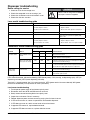
Icemakercleaning&sanitizing
Periodic cleaning of Follett’s icemaker system is required
to ensure peak performance and delivery of clean,
sanitary ice. The following cleaning procedures should be
performed at least as frequently as recommended, and
more often if environmental conditions dictate.
WARNING
• Toreduceriskofelectricalshockdisconnect
powerbeforeservicing
• Wearrubberglovesandsafetygoggles(and/
orfaceshield)whenhandlingicemachine
cleanerorsanitizermixtures
CAUTION
• UseonlyFollettapprovedcleaners(seeprocedurebelow)
• ItisaviolationofFederallawtousethesesolutionsina
manner inconsistent with their labeling
• Readandunderstandallpackaginginstructionsbeforeuse
• Donotusesolvents,abrasivecleaners,metalscrapersor
sharp objects to clean any part of the dispenser
Quarterlyairltercleaning
1. Remove screw at top of louvered panel on left side
of unit.
2. Slide panel toward back of dispenser and lift.
3. Remove the air lter located under the louver.
4. Clean with soap and water.
5. Rinse, and replace when completely dry.
Semi-annualicemakercleaning&sanitizing
Note: If icemaker and dispenser are cleaned and
sanitized at the same time, icemaker should be cleaned
and sanitized rst.
Cleaning solution
SolutionA: Ice machine cleaner: Prepare one gallon
(3.8L) of Follett SafeCLEAN™ Ice Machine cleaner (one
7 oz packet) or equivalent. Solution temperature must be
at least 120 F (49 C).
Warning: Most ice machine cleaners contain citric or
phosphoric acid that can cause skin irritation. Read
caution label on product and follow instructions carefully.
Sanitizingsolution
SolutionB: Prepare sanitizing solution (50 ppm of
available chlorine content) of Ecolab Mikro-chlor Cleaner
or equal chlorinated detergent. Solution temperature
must be 75 F – 125 F (24 C – 52 C).
Note: Before cleaning SensorSAFE units, deactivate
dispenser by depressing and releasing clean switch
located on left side of unit under top front cover. When
cleaning is complete, reactivate by depressing and
releasing clean switch a second time. Dispenser will
automatically reactivate after two minutes.

25CI400A/W • 25HI400A • 50CI400A/W • 50HI400A 11
20. Turn power to icemaker OFF.
21. Disconnect transport tube from evaporator outlet
port. Rinse compression nozzle in clean water and
reinstall on evaporator outlet. Reconnect transport
tube to compression nozzle.
22. Drain any remaining sanitizing solution from
evaporator.
23. Fill reservoir almost to overowing with clean,
120 F (49 C) water, and drain. Repeat three times.
24. Open water supply valve and replace reservoir
cover. Restore power to icemaker and ensure
compressor switch is in ON position. Make ice for
at least 15 minutes to ush any remaining solution
from system. Discard this and all ice made during
sanitizing.
25. Inspect evaporator drain pan and drain line and
remove any accumulated scale build up.
26. Replace any panels removed prior to cleaning.
Start-upfollowingcleaning
1. Clean and sanitize ice storage area of dispenser in
accordance with instructions before making ice.
2. Turn icemaker on and begin to make ice. Icemaker
should start immediately with power and bin signal
supplied.
3. After approximately 30 minutes, test dispenser for
proper dispensing.

12 25CI400A/W • 25HI400A • 50CI400A/W • 50HI400A
CleaningSensorSAFElens
1 Deactivate dispenser by depressing and releasing
clean switch located on left side of unit under top
front cover.
2. Clean lens using soft cloth and mild, non-abrasive
cleaner.
3. Reactivate by dispenser depressing and releasing
clean switch a second time. Dispenser will
automatically reactivate after two minutes.
Semi-annualcleaningandsanitizingof
dispenser hopper
Note: If icemaker and dispenser are cleaned and
sanitized at the same time, icemaker should be cleaned
and sanitized rst.
1. Remove ice from dispenser. Disconnect power.
2. Working inside storage area, remove center
thumbscrew from dispense wheel, tilt wheel up
toward back to clear baffle and disengage wheel
from motor shaft.
3. Remove front cover, chute cover and clear plastic
chute.
4. Wipe lid, wheel, baffle and clear plastic chute with a
clean damp cloth wrung out in cleaning solution A.
5. Rinse all above items with damp cloth wrung out in
clean water.
6. Wipe all bin surfaces (including the area under
dispense wheel) with a damp cloth wrung out in
cleaning solution A.
7. Rinse all bin surfaces thoroughly with damp cloth
wrung out in clean water.
Caution: Do not rinse by pouring water into the
storage bin. Damage to the dispense motor can
result.
8. Sanitize lid, wheel, baffle, clear plastic chute and all
bin surfaces by wiping with a damp cloth wrung out
in sanitizing solution B. DO NOT RINSE.
9. Reinstall dispense wheel and other components.
Dispensercleaning&sanitizing
Periodic cleaning of Follett’s ice and water dispenser
system is required to ensure peak performance and
delivery of clean, sanitary ice. The following cleaning
procedures should be performed at least as frequently
as recommended, and more often if environmental
conditions dictate.
WARNING
• Toreduceriskofelectricalshockdisconnect
powerbeforeservicing
• Wearrubberglovesandsafetygoggles(and/
orfaceshield)whenhandlingicemachine
cleanerorsanitizermixtures
CAUTION
• UseonlyFollettapprovedcleaners(seeprocedurebelow).
• ItisaviolationofFederallawtousethesesolutionsina
manner inconsistent with their labeling
• Readandunderstandallpackaginginstructionsbeforeuse
• Donotusesolvents,abrasivecleaners,metalscrapersor
sharp objects to clean any part of the dispenser
Cleaning solution
SolutionA: Prepare cleaning solution (200 ppm of
available chlorine content) of Ecolab Mikro-chlor Cleaner
or equal chlorinated detergent. Solution temperature
must be 75 F – 125 F (24 C – 52 C).
Sanitizingsolution
SolutionB: Prepare sanitizing solution (50 ppm of
available chlorine content) of Ecolab Mikro-chlor Cleaner
or equal chlorinated detergent. Solution temperature
must be 75 F – 125 F (24 C – 52 C).
Note: Before cleaning SensorSAFE units, deactivate
dispenser by depressing and releasing clean switch
located on left side of unit under top front cover. When
cleaning is complete, reactivate by depressing and
releasing clean switch a second time. Dispenser will
automatically reactivate after two minutes.
Daily cleaning
1. Remove all debris from drain pan.
2. Slowly pour 1 gallon (3.8L) hot water into drain pan
to keep drain lines clear.
Weeklycleaning
1. Wash drain pan and grille with cleaning solution A.
Rinse thoroughly with clean water.
2. Slowly pour solution of one cup (8oz/237ml)
household bleach mixed with one gallon (3.8L) hot
water into drain pan to help prevent algae growth in
drain lines.

25CI400A/W • 25HI400A • 50CI400A/W • 50HI400A 13
Service
Icemakeroperation
Follett’s icemaker consists of four distinct functional systems:
• Refrigeration system
• Water system
• Harvesting system
• Electrical control system
These four systems work together to accomplish the production and harvesting of ice. A problem in any one of these
systems will result in improper operation of the entire ice production cycle. When troubleshooting the icemaker, it is
important to analyze the entire system operation to determine which system is not functioning properly, then pinpoint
the component within that system that is malfunctioning. Determine what corrective action must be taken before
making any adjustments or replacing any components.
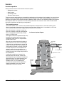
Theicemakingprocess
The Follett icemaker uses a stainless steel jacketed evaporator and operates on a continuous freezing cycle.
Water is supplied to the evaporator from the water reservoir where the water level is controlled by a oat valve.
This valve also shuts off the water supply when the icemaker is not running.
When the icemaker is running, a layer of ice
forms on the interior surface of the evaporator.
This ice is continuously removed by a slowly
rotating (12 RPM) auger.
The auger carries the ice upward into the cavity
formed by the top bearing housing and the
compression loop, where it is compressed to
remove excess water.
When the ice reaches the desired hardness it
rotates within the cavity and is forced through
a discharge port and compression nozzle and
into the ice transport tube. The discharge tube
and compression nozzle are slightly restricted
to further compress the ice and produce the
desired hardness. As the formation of ice
continues, ice in the transport tube is pushed
through the tube to the storage compartment in
the ice dispenser.
A solid state control board, located in the
electrical box of the icemaker, controls the
normal operation of the icemaker and monitors
gearmotor torque. This control board will shut
down the icemaker should an over-torque
condition occur. It is very important that
you familiarize yourself with the operational
sequences detailed in this manual before
attempting to service the icemaker.
Iceharvestsystemdiagram
water
inlet
auger
compression nozzle
ice transport tube
discharge
port

14 25CI400A/W • 25HI400A • 50CI400A/W • 50HI400A
3. Disconnect existing ice tube from engaging pin on
transport tube bracket in ice storage bin and pull
tube up through dispenser chase.
Fig.13
engaging pin
3/16" (5mm) ice tube hole
ice tube mounting bracket
ice level control stat
capillary tube
ice tube
1"
(26mm)
4. Run the new ice transport tube down through chase
making sure that the end with the 3/16" (5mm) hole
is in the bin (Fig. 13).
Fig.14
A
A
1"
(26mm)
Section A – A
.3/16" (5mm)
dia. hole
5. Push the 3/16" (5mm) hole near end of tube into pin
on ice tube bracket (Fig. 14).
6. Reinstall insulation
Fig.15
7. Heat end of transport tube in cup of 160 F (71 C)
hot water to soften (Fig. 15).
8. Slip supplied hose clamp onto tube and push
tube onto compression nozzle on exit port of
evaporator. Do not twist tubing when securing to
evaporator.
9. Secure tube on port with hose clamp, being sure
that clamp is positioned on evaporator side of
nozzle ange.
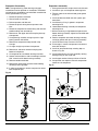
Disassembly and replacement instructions
Dispensewheelremovalandinstallation
1. Remove all ice from storage area of dispenser.
2. Remove center thumb nut from dispense wheel.
3. Remove thumb nuts holding baffle inside bin and
remove baffle.
4. Tilt rear of wheel up and lift off motor drive shaft.
5. After reinstalling wheel, secure baffle loosely with
thumb nuts, but do not tighten.
Fig.12
side view wheel section
dispenser
front
baffle
1/16" (2mm)
spacer
6. Place a 1/16" (2mm) spacer against wheel and
allow baffle to drop until it touches spacer (Fig. 12).
7. Tighten thumb nuts and remove spacer.
Drivebarremoval
1. Remove dispense wheel from dispenser
(see above).
2. Pull drive bar out of its channel in bottom of wheel.
Wheelmotorassemblyremoval
1. Disconnect power.
2. Remove top cover and dispense wheel.
3. Slide icemaker out of dispenser as described on
page 16, icemaker removal. Icemaker does not
need to be removed completely if there is sufficient
clearance to access the dispenser motor through
the right louvered panel.
4. Disconnect wires on motor.
5. Remove four bolts (7/16" socket) holding motor
assembly to bottom of dispenser.
6. Remove motor assembly.
Ice transport tube replacement
CAUTION
• TubingmustbesuppliedbyFollettCorporation
1. Disconnect power. Remove top and partially slide
icemaker out of dispenser as described on page 16.
2. Disconnect end of tube from icemaker.

25CI400A/W • 25HI400A • 50CI400A/W • 50HI400A 15
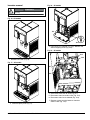
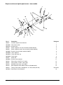
Fig.18–Allmodels
18.1
18.2
3. Lower drain pan protector (Fig. 18.1). Remove and
discard shipping screw (Fig. 18.2).
Fig.19–Allmodels
19.1
19.2
19.4
19.3
4. Close main water shut off valve (Fig. 19.1).
5. Disconnect water line to oat valve (Fig. 19.2).
6. Disconnect water line to solenoid (Fig. 19.3).
7. Remove screws securing bottom of icemaker
electrical box (Fig. 19.4).
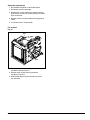
Icemakerremoval
To reduce risk of shock disconnect power before
servicing.
!
WARNING
Fig.16–Allmodels
1. Remove front cover (Fig. 16).
Fig.17–Allmodels
2. Remove splash panel (Fig. 17).

16 25CI400A/W • 25HI400A • 50CI400A/W • 50HI400A
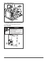
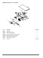
Fig. 22 – All models
22.3
22.2
22.1
22.4
9. Partially slide icemaker from dispenser (Fig. 22.1).
10. Loosen clamp and disconnect ice transport tube
from evaporator (Fig. 22.2).
11. Disconnect power and bin signal twist lock
connectors (Fig. 22.3).
12. Slide icemaker electrical box up and off unit
(Fig. 22.4).
Fig.23–Air-cooledonly
23.2
23.1
13. Use hooks on icemaker electrical box to hang box
on front of condenser (Fig. 23.1).
14. Remove icemaker from dispenser (Fig. 23.2).
Note warning (Fig. 25).
Fig.20–Water-cooledonly
20.1
7. Shut off inlet and outlet valves to water-cooled
condenser and disconnect ttings (Fig. 20.1).
Fig.21–Water-cooledonly
21.1
8. Lift and position water-cooled lines into hook
(Fig. 21.1).

25CI400A/W • 25HI400A • 50CI400A/W • 50HI400A 17
Fig.24–Water-cooledonly
24.2
24.1
13. Use hooks on icemaker electrical box to hang box
on bracket (Fig. 24.1).
14. Remove icemaker from dispenser (Fig. 24.2).
Fig. 25 – All models
TOP
• Electrical box must be in “UP” position
before supplying power
• Start relay is gravity sensitive, and MUST
be in “UP” position
• Failure to comply may cause equipment
to overheat, resulting in equipment failure,
equipment damage or fire hazard
!
WARNING
icemaker
electrical box
TOP

18 25CI400A/W • 25HI400A • 50CI400A/W • 50HI400A
Evaporatorreassembly
1. Clean gearmotor boss, output shaft and shaft well.
2. Install drain pan and evaporator mounting base.
3. Fill gear motor shaft well with food grade grease
(Fig. 27.1).
4. Install condensate shield and seat against gear
motor boss.
5. Install bearing O ring in groove in evaporator
mounting base.
6. Lower bottom bearing assembly into evaporator
mounting base.
7. While maintaining a slight downward pressure on
bottom bearing assembly, tighten hex head bolt with
a 5/16" wrench.
8. Position evaporator over lower bearing assembly
and align grooves with pins in bearing assembly.
9. Install vee band clamp and nut to 70 in/lb.
10. Place auger in center of evaporator and rotate to
mate with drive pin.
11. Install ice compression loop, orienting loop as
shown in Fig. 28.
12. Install upper bearing and seal assembly, rotating
bearing to slip pin into auger slot.
13. Install upper vee band clamp and nut to 70 in/lb.
14. If evaporator was replaced, reinstall compression
nozzle on new evaporator.
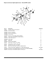
Fig. 27
27.1
Fig. 28
Evaporatordisassembly
Note: The upper bearing, lower bearing and auger
assemblies must be replaced as assemblies. The bottom
and top bearing assemblies cannot be eld assembled to
factory specications (Fig. 26)..
1. Disconnect power to icemaker.
2. Shut off water to icemaker.
3. Drain evaporator and oat tank.
4. Disconnect plastic tubing from evaporator water
inlet.
5. Disconnect compression nozzle tubing and reservoir
overow tubing from secured clip.
6. Remove nut and upper vee band coupling from top
of evaporator
7. Lift top bearing assembly straight up with a slight
rotating motion and remove.
8. Remove ice compression loop located at top
of auger.
9. Lift auger straight up and out of evaporator.
10. Remove nut and lower vee band coupling from
bottom of evaporator.
11. Lift evaporator to clear bottom bearing assembly.
12. Loosen hex head bolt in side of mounting base with
5/16" wrench and lift lower bearing assembly.
13. Remove condensate shield.
14. Remove four Allen head machine screws holding
mounting base to gearbox.
15. If replacing evaporator, remove compression nozzle
from evaporator port.
Fig. 26

25CI400A/W • 25HI400A • 50CI400A/W • 50HI400A 19
Gearmotor replacement
1. Disassemble evaporator as described above.
2. Disconnect the wire connectors.
3. Remove four screws holding gear motor mounting
plate to base of icemaker and lift gearbox and motor
clear of icemaker.
4. Remove machine screws holding mounting plate to
motor.
5. Install new motor in reverse order.
Fanremoval
Fig.29
29.2
29.1
1. Remove screw securing refrigerant lines to
condenser shroud (Fig. 29.1)
2. Remove seven screws securing shroud to
condenser (Fig. 29.2).
3. Slide shroud forward against n block to access
fan and motor.

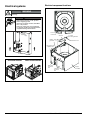
20 25CI400A/W • 25HI400A • 50CI400A/W • 50HI400A
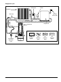
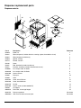
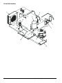
Electrical component locations
bin thermostat
capillary tube
ice level
control stat
Top View
ice tube
mounting bracket
well nut
knurled screw
rubber
grommet
icemaker
electrical
box
dispenser
electrical
box
hopper
assembly
Electrical systems
To reduce risk of shock disconnect power before
servicing.
!
WARNING
TOP
• Electrical box must be in “UP” position
before supplying power
• Start relay is gravity sensitive, and MUST
be in “UP” position
• Failure to comply may cause equipment
to overheat, resulting in equipment failure,
equipment damage or fire hazard
!
WARNING
icemaker
electrical box
TOP
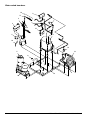
icemaker
electrical
box
icemaker
electrical
box
Air-cooled icemaker
Water-cooled icemaker
Page is loading ...
Page is loading ...
Page is loading ...
Page is loading ...
Page is loading ...
Page is loading ...
Page is loading ...
Page is loading ...
Page is loading ...
Page is loading ...
Page is loading ...
Page is loading ...
Page is loading ...
Page is loading ...
Page is loading ...
Page is loading ...
Page is loading ...
Page is loading ...
Page is loading ...
Page is loading ...
Page is loading ...
Page is loading ...
Page is loading ...
Page is loading ...
Page is loading ...
Page is loading ...
Page is loading ...
Page is loading ...
-
 1
1
-
 2
2
-
 3
3
-
 4
4
-
 5
5
-
 6
6
-
 7
7
-
 8
8
-
 9
9
-
 10
10
-
 11
11
-
 12
12
-
 13
13
-
 14
14
-
 15
15
-
 16
16
-
 17
17
-
 18
18
-
 19
19
-
 20
20
-
 21
21
-
 22
22
-
 23
23
-
 24
24
-
 25
25
-
 26
26
-
 27
27
-
 28
28
-
 29
29
-
 30
30
-
 31
31
-
 32
32
-
 33
33
-
 34
34
-
 35
35
-
 36
36
-
 37
37
-
 38
38
-
 39
39
-
 40
40
-
 41
41
-
 42
42
-
 43
43
-
 44
44
-
 45
45
-
 46
46
-
 47
47
-
 48
48


Follett Symphony 50HI400A User manual
- Category
- Ice cube makers
- Type
- User manual
Ask a question and I''ll find the answer in the document
Finding information in a document is now easier with AI
Related papers
-
Follett Symphony 50HI400A 23 Installation & Service Manual
-
-
Follett 12CI425A-L User guide
-
Follett T5W Operation And Service Manual
-
-
Follett C/E12CI400A User manual
-
-
-
-
Other documents
-
Summit CR1115 CR1115-ASSY.pdf
-
-
Master Flow PT6 Installation guide
-
Cornelius UCR 700 Series User manual
-
 IMI Cornelius, Inc. 700 Installation guide
-
Broan 6" Spacer Kit (20mm Coil) Installation guide
-
Manitowoc Ice F290 H300 Dispensers Installation guide
-
 Cornelius UC 700 Series User manual
-
 Cornelius UC700-A User manual
-


