Honeywell CT1501 User manual

Category
Thermostats
Type
User manual

This manual is also suitable for

Timer Thermostat
Fuel Saver
Heating-Only Thermostat and Wallplate or Heating/Cooling
Thermostat and Subbase Models CT1500, CT1501, CT1502, CT1503
Heat Only—CT1500
Heat/Cool—CT1501
Central Electric Heat/Cool or Single Stage
Heat Pump without auxiliary heat—CT1502
Millivolt Heat—CT1503
OWNER’S MANUAL
69-0333-6
2 69-0333—6
Welcome to the world of energy savings with your new Honeywell Fuel Saver Thermostat. The
Honeywell name is your assurance of accurate control and reliable operation for years to come.
Your new thermostat will automatically control the temperature in your home to provide a high
level of comfort plus energy savings when programmed according to the instructions in this
manual.
Recycling Notice
This control contains mercury in a sealed tube. Do
not
place control in the trash at the end of
its useful life.
If this control is replacing a control that contains mercury in a sealed tube, do
not
place your
old control in the trash.
Contact your local waste management authority for instructions regarding recycling and the
proper disposal of the control, or of an old control containing mercury in a sealed tube.
3 69-0333—6
Table of Contents
PAGE
Features of Your Thermostat .............................................................................................. 4
Reviewing Your Family Schedule ....................................................................................... 7
Setting The Temperature .................................................................................................... 8
Setting Subbase Switches .................................................................................................. 9
Inserting Timer Batteries ................................................................................................... 10
Setting The Timer.............................................................................................................. 11
Programming.....................................................................................................................12
Temporarily changing the program .............................................................................. 15
Troubleshooting ................................................................................................................ 17
Servicing The Thermostat ................................................................................................. 21
System on-time adjustment .......................................................................................... 21
Thermometer adjustment ............................................................................................. 22
Limited One-Year Warranty .............................................................................................. 27
4 69-0333—6
Features of Your Thermostat
1 FLIP-UP COVER. Lift up cover to set timer
for energy savings and normal tempera-
ture periods .
2 THERMOSTAT COVER. Lift up cover and
remove to adjust heat anticipator or install
batteries.
3 THERMOMETER. Provides accurate room
temperature reading.
4 TIMER. Provides 24-hour slotted dial to
hold the programming pins.
5 TIMER SETTING KNOB. Turn clockwise
to match the correct a.m. or p.m. time to
the time indicator.
6 TIME INDICATOR. Arrowhead indicates
time for 24-hour dial.
7 PROGRAM INDEX WHEEL. Controls high
and low temperature at specific time of
day as set by program pins. Can be
moved to temporarily override a schedule.
2
1
3
M8750
5 69-0333—6
8 TEMPERATURE SETTING LEVERS.
Left (blue mark) controls the low tempera-
ture; right (red mark) controls the high
temperature.
9 PROGRAM PINS. Must be inserted into
24-hour timer dial slots to control program
index wheel.
10 PIN SLOTS. Located on 24-hour dial at
ten minute intervals for program pin
insertion.
11 HEAT ANTICIPATOR SCALE PLATE.
Calibrated to match the heating system
current draw in amperes.
12 ANTICIPATOR SETTING LEVER. Must be
adjusted to match the heating system
primary control current.
13 BULB AND BIMETAL ELEMENT (2).
Provides automatic temperature control by
switching the heating or cooling system on
and off.
5
4
8
13
14
9
10
7
6
12
11
M8749
14 AAA ALKALINE BATTERIES (2). Included
to provide power to the timer.
6 69-0333—6
15 WALLPLATE Provides mounting base and
wiring connections for heating-only
thermostat.
16 SUBBASE Provides mounting base, wiring
connections and manual switching control
for heating/cooling thermostat.
M2421
15
AUTO OFF
COOL
HEATON
FAN
B
O
W
Y
R
G
M2411
16
7 69-0333—6
Reviewing Your Family Schedule
Write the answers to the following questions in the spaces provided to determine the program
that fits your family schedule.
SUMMER WINTER
What comfort temperature would you like to maintain? ___________ __________
What energy savings temperature would you like to maintain? ___________ __________
What time does the first person get up in the morning? ___________ __________
Is anyone home all day? ___________ __________
What times does the last person leave in the morning? ___________ __________
What times does the first person return home in the evening? ___________ __________
What time does the last person go to bed? ___________ __________
8 69-0333—6
Setting The Temperature
For Heating:
Set the left lever (blue mark) to the energy
savings temperature you want when you are
sleeping or your home is unoccupied. See Fig. 1.
Set the right lever (red mark) to the tem-
perature you want for normal comfort periods.
NOTE: You may bypass the time program by
setting both the red and blue levers to the
same temperature setpoint.
For Cooling (Not Applicable on
Heating-only Model):
Set the left lever (blue mark)to the tempera-
ture you want for normal comfort periods.
Set the right lever (red mark) to the energy
savings temperature you want when you are
sleeping or your home is unoccupied.
50
60
70
80
50
60 70 80
HIGH
TEMPERATURE
SETTING
LEVER
(RED MARK)
LOW TEMPERATURE
SETTING LEVER
(BLUE MARK)
M8751
Fig. 1—Setting high and low temperature
setting levers.
9 69-0333—6
The subbase fan switch controls fan
operation as follows:
ON—Fan operates continuously.
AUTO—Fan operates with cooling equip-
ment as controlled by the thermostat or
with the heating equipment as controlled
by the plenium fan switch. In electric
heat, heat pump, and fan coil systems,
the fan is controlled by the thermostat in
heating and cooling.
To switch positions, use thumb or index
finger to slide lever to desired position. Stop
switch lever in detent over the desired function
indicator mark for proper circuit operation.
Setting Subbase Switches
(If Applicable)
The subbase system switch controls system
operation as follows:
HEAT—Heating system is controlled by the
thermostat. Cooling system is off.
COOL—Cooling system is controlled by the
thermostat. Heating system is off.
OFF—Both the heating and cooling systems
are off. If the fan switch is in the AUTO
position, the fan is also off.
ON—In a cooling only application, only
cooling operates. In a heating only
application, only heating operates.
10 69-0333—6
Inserting Timer Batteries
Power is supplied to the timer by two AAA
alkaline batteries (included.) Install batteries in
thermostat as shown. See Fig. 2. One a year,
or when batteries are dead, replace with two
new AAA alkaline batteries. We recommend
Energizer® batteries. The thermostat itself will
operate without batteries, but will not operate
as a fuel saver.
BATTERY LOCATION FOR
(2) AAA BATTERIES;
INSTALL WITH POSITIVE
ENDS UP
M8585
Fig. 2—Inserting timer batteries.
11 69-0333—6
Setting The Timer
Lift thermostat flip-up cover to find the 24-hour
program dial, slotted in ten-minute increments.
Adjust the timer to the current time by carefully
turning the knob clockwise . Do
not
reverse the knob.
When time is set correctly, the time indicator
arrow (see Fig. 3) will point to the correct time
and corresponding daytime (light) or nighttime
(dark) band of the program dial.
EXAMPLE: For 11 p.m., the time indicator
arrow will point directly to the dark band on
the dial. For 11 a.m, the arrow will point to
the light band on the dial.
Daylight saving time
When daylight saving time starts, carefully move the knob clockwise one hour. When
daylight-saving time ends, carefully move the knob clockwise 23 hours. Do
not
reverse the
knob, or damage to the timer mechanism may occur.
TIMER
SETTING
KNOB
TIME
INDICATOR
ARROW
M1856
Fig. 3—Setting the timer.
12 69-0333—6
Programming
You can program your thermostat to
automatically lower and raise the temperature
one or more times every 24 hours.
Refer to energy savings chart on the back
cover for typical heating and cooling savings
with your new thermostat.
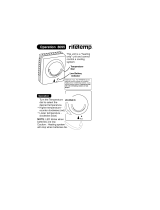
Before setting your program
Lift thermostat flip-up cover to find the
24-hour program dial. The slots on the program
dial (Fig. 4) are for the program pins that can
be inserted at ten-minute intervals.
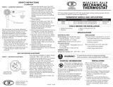
Three red and three blue program pins are
included with your thermostat. The red pins
start the high-temperature period; the blue pins
start the low-temperature period. A heating
program is preprogrammed. A red pin is
inserted at 6:00 a.m. for high temperature
(comfort period); a blue pin is inserted at
10:00 p.m. for low temperature (energy saving
period). Two additional sets of pins are located
in the program pin storage area. You can set
up to six temperature changes with the pins
supplied. We recommend at least five hours for
each energy saving period.
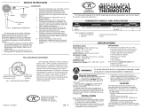
To change the pins or add a new energy
saving period—
To insert a pin, push it straight into the
selected notch on the program dial until it is
completely seated .
To remove a pin, press against the program
dial and pull the pin straight out. Do
not
attempt to change a pin if it is engaged with
the program index wheel.
On heating/cooling systems, you must reset
the pins when the seasons change. You will
also probably want to change the lever
positions.
13 69-0333—6
24-HOUR PROGRAM DIAL
(GRAY AREA FOR NIGHT SETTINGS)
FLIP-UP
COVER
PROGRAM
PINS
THERMOSTAT
COVER
PROGRAM
PIN SLOT
PROGRAM INDEX WHEEL
TIME INDICATOR ARROW
PROGRAM
PIN STORAGE
M8748
Fig. 4—Program components.
Setting the heating program:
Decide when you want the temperature to
reach the comfort level. Find the notch on
the dial that is one-half hour before this time
and insert a red pin. The half-hour head
start gives the furnace time to heat the
house before you wake up or arrive home.
Decide when you want the energy saving
period to start and insert a blue pin at the
notch that corresponds to this time. After the
blue pin engages, the furnace will be off
until room temperature drops to the energy
saving setpoint.
You can set both a day and a night program.
See Fig. 5 for programming examples.
14 69-0333—6
WINTER SUMMER
TEMPERATURE
PROGRAM
PIN IN
CONTROL
NIGHT
ENERGY
SAVING
PERIOD
DAY
ENERGY
SAVING
PERIOD
BEGINS
10:00 PM
ENDS
6:00 AM
BEGINS
7:30 AM
ENDS
4:00 PM
TEMPERATURE
PROGRAM
PIN IN
CONTROL
°C
27
24
27
24
RED
BLUE
RED
BLUE
°F
58
68
58
68
°C
14
20
14
20
°F
80
75
80
75
BLUE
RED
BLUE
RED
M8677
1
1 NOT APPLICABLE ON HEATING-ONLY MODEL.
Setting the cooling program (not
applicable on heating-only model):
Decide when you want the temperature to
reach the comfort level. Find the notch on
the dial that is one-half hour before this time
and insert a blue pin. The half-hour head
start gives the air conditioner time to cool
the house before you wake up or arrive
home.
Decide when you want the energy saving
period to start and insert a red pin at the
notch that corresponds to this time. After the
red pin engages, the air conditioner will be
off until room temperature rises to the
energy saving setpoint.
Fig. 5—Programming examples.
15 69-0333—6
Temporarily changing the program
You may temporarily raise or lower the
temperature if you come home early, stay up
late, plan to be out for the evening, leave on
vacation, etc. You can make a temporary
change one of two ways—moving the program
index wheel or pushing the setting levers
together.
Moving the program index wheel
will change
the program just until the next regularly
scheduled change is due:
Lift the thermostat cover.
Move the program index wheel counter-
clockwise so the time indicator arrow
points to the desired color on the dial.
PROGRAM
INDEX
WHEEL
TIME
INDICATOR
ARROW
M1857
16 69-0333—6
EXAMPLE: If you are currently at the high
temperature period and want to switch to
the low temperature period, move the wheel
from red to blue. If you are currently at the
low temperature period and want to switch
to the high temperature period, move the
wheel from blue to red. The change will be
in effect until the next regularly scheduled
change.
Pushing the setting levers together
will hold
a particular temperature until you change the
levers back. This method is recommended for
a long-term absence:
Simply push both levers to the temperature
you wish for system control. This tempera-
ture will stay in effect until you change the
levers back.
50
60
70
80
50
60 70 80
M2500
17 69-0333—6
Troubleshooting
Your Honeywell thermostat requires little or no attention. Most problems can generally be
traced to the following:
Problem Check Action
No heat. system switch. May be in OFF or
COOL position.
Move system switch to HEAT position.
fuse or circuit breaker. If blown or tripped, replace fuse or reset
breaker.
furnace power switch. May be off. Move switch to ON.
pilot flame (where applicable).
May be out.
Relight pilot flame per furnace manufacturer
instructions.
RH and W thermostat
connections.
Turn off power to furnace. Check for correct
terminal hookups. Repair any frayed or
broken wires. Firmly tighten all terminal
screws.
(continued)
1
18 69-0333—6
Troubleshooting (continued)
Problem Check Action
No heat. (continued) other problem. Contact a qualified service technician for
assistance.
Energy savings
temperature program
12 hours off.
program dial for proper day or
night phase.
Turn timer ahead 12 hours. Move setting
knob clockwise only.
Rooms do not warm
up at programmed
time.
timer program for heating system.
May need more time to warm up
rooms.
Move red pin one-half hour earlier on the
program dial.
Temperature change
occurs at the wrong
time.
programs pins for correct time
locations.
Relocate pins to desired settings.
Room temperatures
are not correct.
positions of thermostat setpoint
levers.
Reset to desired temperatures.
position of subbase system
switch.
Move to desired operating position.
(continued)
19 69-0333—6
Troubleshooting (continued)
Problem Check Action
Heat-on time too
short.
anticipator setting. (See Fig. 6.) Increase anticipator setting by 0.05 Observe
heating system operation.
Heat-on time too
long.
anticipator setting. (See Fig. 6.) Decrease anticipator setting by 0.05.
Observe heating system operation.
No cooling. system switch. May be in OFF or
HEAT position.
Move switch to COOL position.
fuse or circuit breaker. If fuse is blown or breaker tripped, replace or
reset.
condensor switch position.
Located outdoors and may be
turned off.
Move to ON position.
Y, G, RC thermostat connections. Turn off power to cooling system. Check for
correct terminal hookups. Repair any frayed
or broken wires. Firmly tighten all terminal
screws.
(continued)
1
20 69-0333—6
Troubleshooting (continued)
Problem Check Action
No cooling.
(continued)
other problem. Contact a qualified service technician for
assistance.
Timer does not run. batteries may not have been
installed.
Install as shown on page 10.
level position of thermostat. Replace with two new AAA alkaline batteries
as shown on page 10.
Thermostat setting
and thermometer
reading disagree.
area around thermostat for drafts
or radiant heat.
Reinstall thermostat wallplate or subbase.
Use a spirit level. Thermostat should be
about 5 ft [1.5m] above floor on an inside
wall. Contact qualified service technician for
change of location.
calibration of thermometer. See instructions on page 22.
Not applicable on heating-only model.
  • Page 1 1
  • Page 2 2
  • Page 3 3
  • Page 4 4
  • Page 5 5
  • Page 6 6
  • Page 7 7
  • Page 8 8
  • Page 9 9
  • Page 10 10
  • Page 11 11
  • Page 12 12
  • Page 13 13
  • Page 14 14
  • Page 15 15
  • Page 16 16
  • Page 17 17
  • Page 18 18
  • Page 19 19
  • Page 20 20
  • Page 21 21
  • Page 22 22
  • Page 23 23
  • Page 24 24
  • Page 25 25
  • Page 26 26
  • Page 27 27
  • Page 28 28

Honeywell CT1501 User manual

Category
Thermostats
Type
User manual
This manual is also suitable for

Ask a question and I''ll find the answer in the document

Finding information in a document is now easier with AI