
VisionPRO
®
TH8000 Series
Touch-screen Programmable Thermostat
® U.S. Registered Trademark.
Copyright © 2012 Honeywell International Inc.
All rights reserved.
Installation
Guide
69-2693-01
System Types
• Gas,oil,orelectricheatwithair
conditioning
• Warmair,hotwater,
highefficiencyfurnaces,heat
pumps,steam,gravity
• Heatonly—two-wiresystems,
power to open and close zone
valves(Series20),andnormally
open zone valves
• Heatonlywithfan
• Coolonly
• 750mVheatingsystems
This manual covers the following models
• TH8110U:For1Heat/1Coolsystems
• TH8320U:Forupto3Heat/2Coolsystems
• TH8321U:Forupto3Heat/2Coolsystemswithdehumidification
(Pull thermostat from wallplate and turn over to find model number)
Need Help?
Forassistancewiththisproductpleasevisithttp://customer.honeywell.com
or call Honeywell Customer Care toll-free at 1-800-468-1502
This thermostat contains a Lithium battery which may contain Perchlorate material.
PerchlorateMaterial—specialhandlingmayapply,
Seewww.dtsc.ca.gov/hazardouswaste/perchlorate

Installation Guide
2
69-2693—01
ENGLISH
MCR29481
+
+
+
MCR29480
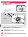
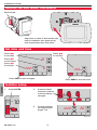
Wallplate installation
1. Separate wallplate from thermostat.
2. Mount wallplate as shown below.
MERCURY NOTICE
Ifthisproductisreplacingacontrolthatcontainsmercuryinasealedtube,donot
place the old control in the trash. Contact your local waste management authority for
instructions regarding recycling and proper disposal.
Grasptopandbottomofwallplate
and pull to remove from thermostat.
CAUTION: ELECTRICAL HAZARD
Can cause electrical shock or equipment damage. Disconnect power before
beginning installation.
Drill3/16”holesfordrywall.
Drill7/32”holesforplaster.
Wallanchors
Wirehole Mounting screws
Must be installed by a trained, experienced technician
• Readtheseinstructionscarefully.Failuretofollowtheseinstructions
can damage the product or cause a hazardous condition.

VisionPRO
TM
TH8000 Series
3
69-2693—01
ENGLISH
NOT
USED
MCR29483
NOT
USED
MCR29482
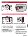
For24VACprimarypower,connectcommon
sideoftransformerto“C”terminal.
Insert supplied batteries for
primary or backup power.
Power options
Push excess wire back into the wall opening. Plug
wall opening with non-flammable insulation.
Remove factory-installed jumper
only for two-transformer systems.
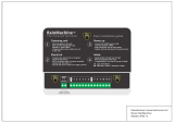
Conventional Terminal Letters:
R Heating power. Connect to secondary
side of heating system transformer.
Rc Cooling power. Connect to secondary
side of cooling system transformer.
C Common wire from secondary side of
cooling transformer (if 2 transformers).
W 1st stage heat relay.
W2 2nd stage heat relay.
Y 1st stage compressor contactor.
Y2 2nd stage compressor contactor.
G Fanrelay.
S1 Optional outdoor or remote sensor.
S2 Optional outdoor or remote sensor.
Heat Pump Terminal Letters:
R Heating power. Connect to secondary
side of heating system transformer.
Rc Cooling power. Connect to secondary
side of cooling system transformer.
C Common wire from secondary side of
cooling system transformer.
Y 1st stage compressor contactor.
Y2 2nd stage compressor contactor.
Aux/E
Auxiliary/Emergencyheatrelay.
G Fanrelay.
L Heat pump reset (powered continuously
whenSystemissettoEmHeat;system
monitorwhensettoHeat,CoolorOff).
O/B Changeover valve for heat pumps.
S1 Optional outdoor or remote sensor.
S2 Optional outdoor or remote sensor.
Terminal Designations Shaded areas below apply only to TH8320/TH8321.
Wiring

Installation Guide
4
69-2693—01
ENGLISH
Wiring guide—conventional systems
Wiring
1H/1C System (1 transformer)
Rc Power [1]
R [R+Rc joined by jumper]
W Heat relay
Y Compressor contactor
G Fanrelay
C 24VACcommon[3]
S1 Optionaloutdoor/remotesensor
S2 Optionaloutdoor/remotesensor
Heat Only System
Rc Power [1]
R [R+Rc joined by jumper]
W Heat relay
C 24VACcommon[3]
S1 Optionaloutdoor/remotesensor
S2 Optionaloutdoor/remotesensor
Heat Only System (Series 20)
Rc [R+Rc joined by jumper]
R Series20valveterminal“R”[1]
W Series20valveterminal“B”
Y Series20valveterminal“W”
C 24VACcommon[3]
S1 Optionaloutdoor/remotesensor
S2 Optionaloutdoor/remotesensor
2H/2C System (1 transformer)
Y2 Cool relay 2
W2 Heat relay 2
Rc Power [1]
R [R+Rc joined by jumper]
W Heat relay 1
Y Cool relay 1
G Fanrelay
C 24VACcommon[3]
S1 Optionaloutdoor/remotesensor
S2 Optionaloutdoor/remotesensor
1H/1C System (2 transformers)
Rc Power (cooling transformer) [1,2]
R Power (heating transformer) [1,2]
W Heat relay
Y Compressor contactor
G Fanrelay
C 24VACcommon[3,4]
S1 Optionaloutdoor/remotesensor
S2 Optionaloutdoor/remotesensor
Heat Only System With Fan
Rc Power [1]
R [R+Rc joined by jumper]
W Heat relay
G Fanrelay
C 24VACcommon[3]
S1 Optionaloutdoor/remotesensor
S2 Optionaloutdoor/remotesensor
Cool Only System
Rc Power [1]
R [R+Rc joined by jumper]
Y Compressor contactor
G Fanrelay
C 24VACcommon[3]
S1 Optionaloutdoor/remotesensor
S2 Optionaloutdoor/remotesensor
2H/2C System (2 transformers)
Y2 Cool relay 2
W2 Heat relay 2
Rc Power (cooling transformer) [1,2]
R Power (heating transformer) [1,2]
W Heat relay 1
Y Cool relay 1
G Fanrelay
C 24VACcommon[3,4]
S1 Optionaloutdoor/remotesensor
S2 Optionaloutdoor/remotesensor
See [notes] below
[1] Power supply. Provide disconnect means and overload protection as required.
[2] Remove jumper for 2-transformer systems.
[3] Optional24VACcommonconnection.
[4] Common connection must come from cooling transformer.
Shaded areas below apply only to TH8320/TH8321.

VisionPRO
TM
TH8000 Series
5
69-2693—01
ENGLISH
1H/1C Heat Pump (no auxiliary heat)
Rc Power [1]
R [R+Rc joined by jumper]
O/B Changeover valve [5]
Y Compressor relay
G Fanrelay
C 24VACcommon[3]
S1 Optionaloutdoor/remotesensor
S2 Optionaloutdoor/remotesensor
2H/1C Heat Pump (with auxiliary heat)
L Equipmentmonitor[6,7]
Aux/E Auxiliary/Emergencyheatrelay(Heat2)
Rc Power [1]
R [R+Rc joined by jumper]
O/B Changeover valve [5]
Y Compressor relay
G Fanrelay
C 24VACcommon[3]
S1 Optionaloutdoor/remotesensor
S2 Optionaloutdoor/remotesensor
2H/2C Heat Pump (no auxiliary heat)
Y2 Compressor 2 relay
Rc Power [1]
R [R+Rc joined by jumper]
O/B Changeover valve [5]
Y Compressor 1 relay
G Fanrelay
C 24VACcommon[3]
S1 Optionaloutdoor/remotesensor
S2 Optionaloutdoor/remotesensor
3H/2C Heat Pump (with auxiliary heat)
Y2 Compressor 2 relay
L Equipmentmonitor[6,7]
Aux/E Auxiliary/Emergencyheatrelay(Heat2)
Rc Power [1]
R [R+Rc joined by jumper]
O/B Changeover valve [5]
Y Compressor 1 relay
G Fanrelay
C 24VACcommon[3]
S1 Optionaloutdoor/remotesensor
S2 Optionaloutdoor/remotesensor
Shaded areas below apply only to TH8320/TH8321.
Wiring guide—heat pump systems
Wiring
See [notes] below
[1] Power supply. Provide disconnect means and overload protection as required.
[3] Optional24VACcommonconnection.
[5] O/B set to control as either O or B in installer setup.
[6] If Lterminalisused,24VACcommon(terminalC)must be connected.
[7] Heatpumpreset(poweredcontinuouslywhenthermostatissettoEm.Heat;systemmonitor
whensettoHeat,Cool,orOff).

Installation Guide
6
69-2693—01
ENGLISH
SCHEDHOLD
TUE
FAN
AUTO
Inside
70
aM
6:00
SYSTEM
HEAT
DONE
20
0120
DONE CANCEL
aM
6:00
SYSTEM
HEAT
MCR29486
DONE
TUE
15
6
2012
DONE
TUE
PM
1:00
MCR29485
MCR29484
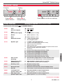
Remove tab.
Align pins on back of thermostat with
slotsinwallplate,thenpushgently
until thermostat snaps into place.
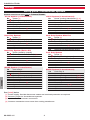
Remove tab and mount thermostat
Set date and time
Press st
to set time
Press st
to set date
Press st
to set month
Press st
to set year
Installer setup
Press DONE to save changes.
Press DONE to save and exit.
1. Press SYSTEM.
2. Press and hold
these two buttons
until the display
changes.
3. Changesettings
as required (see
pages7-9).

VisionPRO
TM
TH8000 Series
7
69-2693—01
ENGLISH
DONE
20
0120
DONE
20
0120
MCR29486
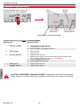
Installer setup
SettingFunction
Press DONE to exit & save settings.
Press st to
select function
Press st to
change setting
Setup functions Settings & Options (factory default in bold)
Shaded areas below apply only to TH8320/TH8321.
0120 Year
(rst two digits)
20 (2001-2099)
21 (2100-2178)
0130 Year
(second two digits)
12 (2012)
[Otheroptions:00-99]
0140 Month 6 [Otheroptions:1-12]
0150 Date 15 [Otheroptions:1-31]
0160 Schedule format 4 7-day programming
0 Non-programmable
0170 System type 1 1 heat/1 cool conventional
2 1heat/1coolheatpump(noaux.heat)
3 Heatonly(2-wiresystems)
4 Heatonlywithfan
5 HotwaterSeries20system(powertoopen&closezone
valves/normallyopenzonevalves)
6 Coolonly
7 2heat/1coolheatpump(withaux.heat)
8 2heat/2coolmultistageconventional
9 2heat/1coolmultistageconventional
10 1heat/2coolmultistageconventional
11 2heat/2coolheatpump(noaux.heat)
12 3heat/2coolheatpump(withaux.heat)
0180 Fan control
(heating)
0 Gas/Oil heat (equipment controls heating fan)
1 Electricfurnace(thermostatcontrolsheatingfan)
0190 Changeover valve
(O/B terminal)
0 O/B terminal controls valve in cooling
1 O/Bterminalcontrolsvalveinheating
0200 Auxiliary heat 0 Electric backup heat
1 Fossilfuelbackupheat
0210 External fossil
fuel kit
1 External fossil fuel kit controls backup heat
0 Thermostat controls backup heat (outdoor sensor required)
0220 1st stage com-
pressor cycle rate
3 Recommended for most compressors
[Otheroptions:1,2,4,5or6CPH]
0230 2nd stage com-
pressor cycle rate
3 Recommended for most compressors
[Otheroptions:1,2,4,5or6CPH]
Continued on next page

Installation Guide
8
69-2693—01
ENGLISH
Setup functions Settings & Options (factory default in bold)
Shaded areas below apply only to TH8320/TH8321.
0240 First stage heat
cycle rate (CPH=
cycles per hour)
5 Gas or oil furnaces of less than 90% efciency
1 Steam or gravity systems
3 Hotwatersystems&furnacesof90%+efciency
9 Electricfurnaces
[Otheroptions:2,4,6,7,8,10,11,12CPH]
0250 Second stage heat
cycle rate (CPH)
5 Gas or oil furnaces of less than 90% efciency
1 Steam or gravity systems
3 Hotwatersystems&furnacesof90%+efciency
9 Electricfurnaces
[Otheroptions:2,4,6,7,8,10,11,12CPH]
0260 Third stage heat
cycle rate (CPH)
9 Electric auxiliary heat or electric furnaces
1 Steam or gravity systems
3 Hotwatersystems&furnacesof90%+efciency
5 Gasoroilfurnacesoflessthan90%efciency
[Otheroptions:2,4,6,7,8,10,11,12CPH]
0280 Backlight 0 Backlight on for approx. 8 seconds after keypress
1 Backlightalwaysonlowintensity,fullbrightafterkey-
press(requires24VACconnection)
0300 Manual/Auto
changeover
0 Manual changeover (Heat/Cool/Off)
1 Automaticchangeover(Heat/Cool/Auto/Off)
0310 Auto changeover
deadband
3 Heat/cool temperature 3°F apart (1.5°C) ** See page 11
[Otheroptions:2-9(2°Fto9°F/1.5°Cto5°C)]
0320 Temperature
display
0 Fahrenheit
1 Celsius
0330 Daylight savings 2 Auto-change to daylight savings time(2007andbe-
yond,forareasthatusethenew2007DSTcalendar)
1 Auto-changetodaylightsavingstime(through2006,and
for areas that do notusethenew2007DSTcalendar)
0 Daylight savings time is turned off
0340 Remote sensor 0 No remote sensor
1 Outdoor sensor (display only)
2 Outdoor control sensor (select heat pumps) ** See page 11
3 Indoor sensor
0350 Heat pump
compressor lockout
0 No heat pump compressor lockout
[Otheroptions:15,20,25,30,35,40°F(-9.5°Cto7°C)]
0360 Heat pump
auxiliary lockout
0 No heat pump auxiliary lockout
[Otheroptions:40,45,50,55,60°F(4.5°Cto15.5°C)]
0380 Dehumidication
control
0 No dehumidication control
1 Thermostatcontrolsdehumidicationwithairconditioner
** See page 11
Installer setup
Continued on next page

VisionPRO
TM
TH8000 Series
9
69-2693—01
ENGLISH
Setup functions Settings & Options (factory default in bold)
0500 Furnace lter
change reminder
0 Off
1 10-day run time (about 1 month)
2 30-dayruntime(about3months)
3 60-dayruntime(about6months)
4 90-dayruntime(about9months)
5 120-dayruntime(about1year)
6 365-dayruntime(about3years)
0510 Humidier pad
change reminder
0 Off
1 90calendardays
2 180calendardays
3 365calendardays
0520 UV lamp change
reminder
0 Off
1 365calendardays
0530 Adaptive Intelligent
Recovery™
1 On ** See page 11
0 Off
0540 Program periods 4 4 program periods (Wake, Leave, Return, Sleep)
2 2programperiods(Wake,Sleep)
0580 Compressor
protection
5 5 minute compressor off time ** See page 11
[Otheroptions:0,1,2,3or4-minuteofftime]
0600 Heat temperature
range stop
90 Max. heat temperature setting is 90°F (32°C)
[Otheroptions:40-89°F(4.5°Cto32°C)]
0610 Cool temperature
range stop
50 Min. cool temperature setting is 50°F (10°C)
[Otheroptions:51-99°F(10.5°Cto37°C)]
0640 Clock format 12 12-hour time (i.e., “3:30 pm”)
24 24-hourtime(i.e.,“15:30”)
0650 Extended fan
timer (heat)
0 Off
90 Fanrunsfor90secondsaftercallforheatends
0660 Extended fan
timer (cool)
0 Off
90 Fanrunsfor90secondsaftercallforcoolingends
0670 Keypad lock 0 Keypad unlocked (fully functional)
1 Partially locked (access to temperature settings only)
2 Fullylocked
0680 Heat temperature
control
2 Standard temperature control (recommended)
1 Choose if room is warmer than set temperature
3 Chooseifroomdoesnotreachsettemperature
0690 Cool temperature
control
2 Standard temperature control (recommended)
1 Choose if room is cooler than set temperature
3 Chooseifroomdoesnotreachsettemperature
0700 Temperature
display offset
0 Thermostat displays actual room temperature
[Otheroptions:-3,-2,-1,1,2,3°Foffset(-1.5°Cto1.5°C)
0710
RESET
0 No reset
1 Reset installer options & program schedule to factory
default (only date and time settings are retained)
Installer setup

Installation Guide
10
69-2693—01
ENGLISH
DONE
20
0120
DONE
1
0
TEST
MCR29488
Duringinstallersetup,presst
repeatedlyuntil“Test”appears.
Test
number
System
status
Press st to
select test
Press st to
change status
Press DONE to terminate testing.
Shaded areas below apply only to TH8320/TH8321.
1 Cooling system 0 Compressor and fan turn off
1 Compressor and fan turn on
2 Second stage compressor turns on
2 Fan system 0 Fanturnsoff
1 Fanturnson
3 Heating system 0 Heat and fan turn off
1 Heatturnson(fanonifFunction0170issetforheatpump,
orifFunction0180issetto“1”)**Seepage6
2 Second stage heat turns on
3 Thirdstageheatturnson
4 Emergency
heating system
0 Heat and fan turn off
1 Heat and fan turn on
System test System status
CAUTION: EQUIPMENT DAMAGE HAZARD. Compressor protection is bypassed
duringtesting.Topreventequipmentdamage,avoidcyclingthecompressorquickly.
Installer system test

VisionPRO
TM
TH8000 Series
11
69-2693—01
ENGLISH
Auto Changeover(SetupFunction0300):WhensettoAuto,thethermostatautomaticallyselects
heating or cooling depending on the indoor temperature. Heat and cool settings must be at least 2 de-
greesapart.Iffunction0380issettoOn,theheatandcoolsettingsmustbeatleast5degreesapart.
Remote Sensor(SetupFunction0340):Ifanoptionaloutdoorsensorisinstalled,thethermostatcan
displaytheoutsidetemperature.Ifanoptionalremoteindoorsensorisinstalled,thethermostatwill
display the temperature at the sensor location (the internal sensor in the thermostat is not used).
Adaptive Intelligent Recovery(SetupFunction0530):Allowsthethermostatto“learn”howlongthe
furnaceandairconditionertaketoreachprogrammedtemperaturesettings,sothetemperatureis
reached at the scheduled time.
Compressor Protection(SetupFunction0580):Forcesthecompressortowaitafewminutesbefore
restarting,topreventdamage.Duringthistime,themessage“Wait”ashesonthedisplay.
Dehumidication control(SetupFunction0380):TH8321models monitor the indoor humidity level
and automatically activate the cooling system to reduce humidity by lowering the temperature by up
to3degreesbelowthecurrentcoolsetting.
Heat Pump Temperature Lockout (with fossil-fuelbackup):Ifthethermostatisinstalledwithan
optionaloutdoorsensor,youcanselectacompressorlockouttemperature(Function0350).When
theoutdoortemperatureisbelowthelockouttemperature,onlytheauxiliaryheatoperates.Whenthe
outdoortemperatureisabovethelockouttemperature,onlythecompressoroperates.
Heat Pump Temperature Lockouts (with electric heatbackup):Ifthethermostatisinstalledwith
anoptionaloutdoorsensor,youcanselectacompressorlockouttemperature(Function0350)and/
oranauxiliaryheatlockouttemperature(Function0360).Whentheoutdoortemperatureisbelowthe
compressorlockouttemperature,onlytheauxiliaryheatoperates.Whentheoutdoortemperatureis
abovetheauxiliarylockouttemperature,onlythecompressoroperates.Iftheoutdoortemperatureis
betweenthecompressorandauxiliarylockouttemperatures,boththecompressorandauxiliaryheat
can operate.
Shaded areas below apply only to TH8320/TH8321.
Special functions
Please contact your distributor to order replacement parts.
Outdoor temperature sensor .............................. PartNumberC7089U1006
Remote indoor temperature sensor .................. PartNumberC7189U1005
Cover plate* ............................................................ PartNumber32003796-001
*(Use to cover marks left by old thermostats.)
Accessories & replacement parts

Installation Guide
Honeywell International Inc.
1985DouglasDriveNorth
GoldenValley,MN55422
http://customer.honeywell.com
Automation and Control Solutions
® U.S. Registered Trademark.
© 2012 Honeywell International Inc.
69-2693—01M.S.01-12
Printed in U.S.A.
Temperature Ranges
• Heat:40°to90°F(4.5°to32°C)
• Cool:50°to99°F(10°to37°C)
Operating Ambient Temperature
• 0°to120°F(-18°to48.9°C)
Shipping Temperature
• -30°to150°F(-34°to66°C)
Operating Relative Humidity
• 5%to90%(non-condensing)
Physical Dimensions
• 4-9/16”Hx6”Wx1-3/8”D
• 116mmHx152mmWx35mmD
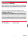
Electrical Ratings
Terminal Voltage(50/60Hz) RunningCurrent
WHeating 20-30Vac 0.02-1.0A
(Powerpile) 750mVDC 100mADC
W2Heating 20-30Vac 0.02-0.6A
YCooling 20-30Vac 0.02-1.0A
Y2Cooling 20-30Vac 0.02-0.6A
Aux/EAux.heat 20-30Vac 0.02-1.0A
Emergencyheat
O/BChangeover 20-30Vac 0.02-0.6A
LHeatpumpreset 20-30Vac 0.02-0.6A
Specifications
Need Help?
Forassistancewiththisproductpleasevisithttp://customer.honeywell.com
or call Honeywell Customer Care toll-free at 1-800-468-1502
-
 1
1
-
 2
2
-
 3
3
-
 4
4
-
 5
5
-
 6
6
-
 7
7
-
 8
8
-
 9
9
-
 10
10
-
 11
11
-
 12
12


Honeywell VISIONPRO TH8110U User manual
- Category
- Thermostats
- Type
- User manual
Ask a question and I''ll find the answer in the document
Finding information in a document is now easier with AI
Related papers
-
Honeywell VisionPRO TH8000 Series Installation guide
-
Honeywell Thermostat TH8000 User manual
-
-
Honeywell 8000 User manual
-
-
-
Honeywell TH8000 User manual
-
-
-
Other documents
-
Lennox X4147 Installation Instructions Manual
-
-
Bard 8403-058 User manual
-
Avision DF-0510 Installation guide
-
Trane TCONT600AF11MA Installation Instructions Manual
-
-
-
clare CLR-CH-TSB10-WF Installation guide
-
WarmlyYours TH8321WF1001 Installation guide
-
 RainMachine SPK3-16 Installation guide
