Page is loading ...

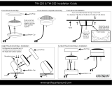
MM400 Tweeter
MM455 5.25" System
MM465 6.5" System

P O L K A U D I O / M O M O D E S I G NA M E R I C A N P O W E R , I T A L I A N F I N E S S E
Attach your receipt
here and file for future
reference. It may
be required for
warranty service.
X
A Wo rd From Matthew Polk
Dear Music Lover,
You have just entered a new realm of car audio!
I am extremely excited about these Polk
Audio/MOMO high performance speakers; this
is the first time that the exclusive MOMO Design
house of Italy has co-branded a product. We’ve
partnered with them to produce the best sound-
ing, best looking car speakers ever. They are
going to make your car look and sound great.
They may not look like any other Polk Audio
speaker, but make no mistake: They contain the
latest loudspeaker technology and many
of our exclusive sound innovations, like Dynamic Balance
®
for clean sound and low
distortion. You can be assured of outstanding performance and unmatched quality, as
well as an exciting new look.
Please take a moment to read through this manual. It will help you get the greatest
possible enjoyment from these fine instruments. If you have questions, or would like more
information on building the car audio system of your dreams, don’t hesitate to call our
Customer Service Department at (800) 377-7655 from 9am to 6pm Eastern Standard Time,
Monday through Friday.
Grazie!
Matthew Polk

P O L K A U D I O / M O M O D E S I G NA M E R I C A N P O W E R , I T A L I A N F I N E S S E
The Story of Dynamic Balance
®
Your new Polk speakers employ Dynamic Balance, a technology that came out of a joint
research project between Polk Audio and Johns Hopkins University. This laser imaging
research enables us to view the entire vibrating surface of a driver or tweeter, allowing us to
observe the resonances that develop on speaker cones as they move. These resonances are
the root cause of frequency response distortions.
As an x-ray enables a physician to discover the root cause of a symptom and thereby pre-
scribe the right treatment for a cure, this laser imaging technique allows Polk engineers to
find the right combination of high-tech materials, geometry and construction techniques
to tune out the offending resonances. The benefit of Dynamic Balance is the dramatic
improvement in the sound quality of our speakers, which every listener can appreciate. You
no longer have to choose between excellent bass and smooth, clear midrange and highs.
Now you can have it all, thanks to Dynamic Balance technology.
Polk Audio—A History of Excellence
Like the way these great new speakers sound in your car? You’ll love the way Polk Audio
speakers sound in your living room! Polk Audio has been making world-class loudspeakers
since 1972. Polk’s dedication to fundamental research has resulted in over 25 patents.
Polk loudspeakers have earned the praise of audio experts the world over, garnering dozens
of awards for innovative, high-quality design. Whether you desire audiophile-quality sound
for your home, car or even your multimedia computer, Polk loudspeakers deliver
unmatched performance and value.
See the full line of Polk Audio loudspeakers at your Polk Audio dealer, or at
www.polkaudio.com
Concentric breakup of cone
produces distortion
Radial breakup of cone
produces distortion
Polk “Dynamic Balance”
design results in
low distortion
Laser Interferometry tests produced holographic “photos” of drivers
in motion. The “bad” drivers are experiencing modal breakup that
results in performance-robbing resonances. A “perfect” driver would
look like a cake (flat on top), more, like the photo on the right.

P O L K A U D I O / M O M O D E S I G NA M E R I C A N P O W E R , I T A L I A N F I N E S S E
Read this manual thoroughly first. If you have any doubts about your ability to execute
any of the installation steps, save yourself a lot of grief and contact a professional installer
(your Polk dealer is a good place to find one).
If you intend to do the installation yourself we assume that you possess some skill in the
proper use of hand and power tools. No matter how much installation experience you have,
it’s always a good idea to:
• Read this manual thoroughly before you begin.
• Plan your installation carefully.
• Allow enough time to complete the installation without rushing.
• Protect your car from unwanted scratches.
Necessary To o l s
• Phillips head screwdriver
• 9/16" allen wrench
• Flat blade screwdriver or putty knife
• Electric drill
• 1/4" and 1/8" drill bits
• Reciprocating saw or razor knife
• Magic marker for marking the cutout (new location only)
• Metal cutting tool (hole saw, if you intend to cut metal
• Metal file
• Soldering iron or a supply of solderless connectors
• Safety glasses
• Wire strippers and cutters
• Crimping tool
All Polk Audio/MOMO Drivers Feature :
• Futuristic cast aluminum baskets that mimic MOMO wheel designs
• Elegant matching motor cup conceals a beefy magnet structure
• Rugged, highly conductive pro-grade nickel-plated binding posts
• Polymer/mica composite cones
• Aramid fiber spiders for greater dynamic range
• 6.5” mid/driver features 1.5” voice coil, 5.25” mid/driver features 1” voice coil
• Woven carbon-fiber dustcaps
Polk Audio/MOMO Tweeters Feature :
• Lightweight red fabric dome tweeters for flat response, great inner detail and
low distortion
• Neodymium magnets that are small and powerful
• Low viscosity ferro-magnetic cooling fluid for superior power handling
• Surface and flush-mount swivel cups allow fine tuning of the tweeter angle for
better soundstaging
Component System Crossovers Feature :
• Gold plated terminals
• Air-core inductor for low distortion
• Mylar capacitors for cleaner, more transparent highs
• Tweeter level control to fine-tune the tonal balance of your system
• Midrange Extension switch bypasses the low-pass filter for better driver-to-
tweeter blending when the two components are separated by a great distance
Getting Started
Please inspect each loudspeaker carefully. Notify your Polk dealer if you notice any
damaged or missing items. Keep the carton and packing material. They will do the best
job of protecting your speakers if they need to be transported. Check that you have the
following parts:
MM455 and MM465
2 mid/ woofers
2 tweeters
2 crossover networks
2 tweeter flush mount cups
2 flush mount cup clamps
2 tweeter surface mount cups
2 grilles
8 - #8 screws with 9/16” Allen head
8- screw clips
2- #4 Philips head screws
Tweeter hook- up wire
Mid/ woofer hook- up wire
Registration card
MM400:
2 tweeters
2 in- line crossover networks
2 tweeter flush mount cups
2 flush mount cup clamps
2 tweeter surface mount cups
Registration card

P O L K A U D I O / M O M O D E S I G NA M E R I C A N P O W E R , I T A L I A N F I N E S S E
Installing the Polk/MOMO System Mid/Woofers in Factory Locations
Most cars have speaker grilles that blend with the rest of the car’s interior. Sometimes it is
difficult to determine how to remove these grilles to gain access to the speaker that you intend
to replace. If you have one of these grilles, you may want to consider using a professional
installer. On some cars, the grilles are held by screws or spring clips. The screws will be
obvious, the spring clips won’t.
If there are screws, remove them, put them in a safe spot, and remove the grilles. To remove a
clip-on grille, use your flat-blade screwdriver or a putty knife to gently pry up the grille. If it
resists, back off and think again about the professional install. The cost of one of these can
sometimes be less than the cost of new door panels. Some grilles are integral parts of the door
panel and are not removable. In these cases you will need to remove the entire door panel to
gain access to the speaker location.
This will usually require removal of door handles, window mechanisms, and other parts such
as door pulls and lock buttons.
1 . Once you get the grille off, remove the factory speakers. Save the hardware.
You may be able to reuse it to mount your new speaker.
2 . Cut the supplied driver wire (the heavier gauge of the two sets of wire) in half.
3 . Remove the yellow crossover cover by squeezing the cover at the tabs. Attach
speaker wires to the crossover “woofer” terminals. Attach the wire with the white
stripe to the positive (+) terminal screw, and the un-striped wire to the negative (-)
terminal screw.
4 . Route the driver wire from the crossover location to the mid/woofer location.
5 . Strip 1/8” – 1/4” (4-6 mm) of plastic insulation from the cut ends of the driver wire.
6 . Unscrew the binding post thumbnuts on the mid/woofers to fully expose the hole in
the terminal shaft and slip the other end of the wire into the holes in the input ter-
minals. Tighten the thumbnuts finger-tight (do not over-tighten the nuts as you
may strip the threads). Be sure to attach the wire with the white stripe to the posi-
tive (red) terminal, and the un-striped wire to the negative (black) terminal.
7 . If the factory speaker had three screw holes, you’ll need to drill additional screw
holes to accommodate the four screw pattern of the Polk/MOMO mid/woofer.
8 . Using the hardware retained from the factory speaker or the screw clips supplied
with the Polk/MOMO speaker, secure your new speaker to the car panel.
Installing the Components
The Polk/MOMO System Crossovers
You will need to make wiring connections from your amp or radio to the crossovers and from
the crossovers to your mid/woofers and tweeters (Figure 1). Choose crossover box locations
that are convenient for making these connections. As there are adjustments on and in the
crossover networks which you will need to access during the “fine tuning” stage of the instal-
lation, place them in a spot that’s easy to get to. Once you’re done fine-tuning the system, the
crossovers can be hidden away and secured.
Your Polk/MOMO Series crossovers have clearly marked terminals. Before making connections
between your crossovers, mid/woofers and tweeters, refer to Figure 1. The wires provided with
your Polk/MOMO System have one conductor with a white stripe. Use this wire as the positive
(+) lead and connect it to the positive (+) terminals on your crossovers as well as to the posi-
tive (+) terminals of each speaker.
Figure 1
(Note: Crossover is not weather proof)
I N P U T
W O O F E R
T W E E T E R

P O L K A U D I O / M O M O D E S I G N
10
A M E R I C A N P O W E R , I T A L I A N F I N E S S E
11
3 . Without running the wires through doors or under upholstered panels, connect
your Polk/MOMO tweeters to these wires. (See detailed instructions below)
4 . Have a friend sit in the passenger’s seat while you sit in the driver’s seat, each
holding a tweeter in hand.
5. With music playing, position the tweeters in different locations around the pas-
senger compartment, listening for the differences caused from these placements.
We recommend using vocals for this test. You will be able to determine in a short
time the best location for your tweeters. The soundstage or image should “float”
above the dash and not be localized to the physical location of the drivers or
tweeters. Both passenger and driver should be able to hear both channels and a
stereo image.
The Polk MM400 tweeter offers two mounting
options for installation flexibility.
Mounting Option #1—Surface mounting the
MM400 Tweeter
1 . Using the base of the surface mount cup as a
template, mark the screw hole and drill it using a
1/8 inch drill bit. Mark the wire holes (for the
tweeter wires), drill using the 1/4-inch drill bit.
2. Attach the surface mount cup to the panel using
supplied #4 screw.
3. Cut the supplied tweeter wire (the lighter gauge
wire) in half.
4 . Strip 1/8” – 1/4” (4-6 mm) of plastic insulation
from the cut ends of the tweeter wire. Connect
this end of the wire to the tweeter terminals of
the crossover. Connect the white-striped wire
strand to the positive (+) terminal of the
crossover tweeter output and the un-striped wire
to the negative (-) tweeter terminal.
5 . Route the tweeter wire from the crossover to the tweeter location. Push the red
and black tweeter wires through the holes in the bottom of the tweeter cup and
though the panel.
6 . Slip the male fast-on connector on the red tweeter wire onto the female connec-
tor on the white-striped wire from the crossover and the black tweeter wire to
the un-striped wire (Figure 2). Make sure the clear plastic insulators fully cover the
fast-on connectors otherwise you may short the tweeter leads and possibly dam-
age your amplifier.
7 . Mount the tweeters by gently pushing them into the surface mount cup. Be care-
ful not to pinch the wires.
8 . Once the tweeter is mounted and connected, swivel the tweeter to fine-tune the
soundstage image of the system.
Installing the Mid/Woofers in Non-Factory Locations
If you have decided to install your Polk/MOMO Series mid/woofers in locations other than
those provided by the automobile manufacturer, make certain that the location you choose is
clear of all obstructions, both in front of and behind the panel, before you proceed. Pay par-
ticular attention to window mechanisms and any body panels critical to the structural
integrity of the vehicle. The mounting depths and cutout diameters of your Polk/MOMO
Series mid/woofers are listed with all the other important specifications at the end of
this manual.
1. Cut a hole in the panel (5 inch or 127 mm hole for the MM455 and 5-15/16 inch or
150.9 mm hole for the MM465).
2 . Using the speaker grille as a template for marking the locations of the four screw
h o l e s .
3. Drill the holes with a 1/8” bit.
4 . Attach the screw clips to the car panel at the hole locations.
5 . Cut the supplied driver wire (the heavier gauge of the two sets of wire) in half.
6 . Remove the yellow crossover cover by squeezing the cover at the tabs. Attach
speaker wires to the crossover “woofer” terminals. Attach the wire with the white
stripe to the positive (+) terminal screw, and the un-striped wire to the negative (-)
terminal screw.
7 . Route the driver wire from the crossover location to the mid/woofer location.
8 . Strip 1/8” – 1/4” (4-6 mm) of plastic insulation from the cut ends of the driver wire.
9 . Unscrew the binding post thumbnuts on the mid/woofers to fully expose the hole
in the terminal shaft and slip the other end of the wire into the holes in the input
terminals. Tighten the thumb nuts finger-tight (do not over-tighten the nuts as you
may strip the threads). Be sure to attach the wire with the white stripe to the posi-
tive (red) terminal, and the un-striped wire to the negative (black) terminal.
10. Place the grille over the driver and line up the screw holes with the screw clips on
the car panel.
1 1 . Secure the speaker/grille assembly to the car panel with the supplied Allen
head screws.
Polk/MOMO System Tweeters
One important advantage of component systems is their ability, when properly installed, to
improve the soundstage created by the music in your car. The soundstage is the musical “pic-
ture” made up of the instruments and vocalists. The difference in the soundstage will be dra-
matic depending on where you mount your tweeters. We recommend a simple experiment
that will help you decide the best spot for your tweeters in your car. Here are the steps:
1 . Complete the installation of your entire system except for the MM400 tweeters.
2 . Connect the wires provided with your tweeters to the tweeter terminals on your
Polk/MOMO crossovers. (See detailed instructions below)
Figure 2

P O L K A U D I O / M O M O D E S I G N
12
A M E R I C A N P O W E R , I T A L I A N F I N E S S E
13
MM400 Component Tweeter Hook-up
When purchased as a separate unit, the MM400 tweeter includes a crossover network
integrated into the hook-up wires. This high-pass filter allows the MM400 to be used with
other components. It is important to maintain correct polarity. The red wire connects to
the positive (+) amplifier terminal and the black to the negative (-) amplifier terminal.
If your system contains an active crossover, you may bypass the in-line crossover and wire
the tweeter directly to the output terminals of an amplifier that has a high-pass filter
(crossover) on its input. The minimum crossover point should be 2 kHz at 12dB per octave.
DO NOT USE THE TWEETER WITHOUT A CROSSOVER NETWORK.
Damage to the tweeter from thermal overload will result without the protection provided
by a crossover and will void your warranty.
Extending Frequency Response using Mid-Range Extension
The Polk Audio/MOMO Crossover features a Mid-Range Extension option. When placed in
the “ON” position, this removes the low pass crossover filter from the mid/bass driver, allow-
ing it to run full-range. This may be helpful in getting a better “blend” between mid/driver
and tweeter when the two are placed some distance from each other.
Mounting Option #2 - Flush mounting the
MM400 Tweeter
1. Remove the panel on which you are going to mount the
tweeter and check for proper clearance behind it. The
flush mount kit is 13/16 inch deep. Measure to make
sure there is sufficient depth behind the spot you
choose the final location.
2. Use the hole that is punched into the cardboard packing
insert as a template to mark the location and size of the
mounting hole.
3. Mark the center of the spot and cut a hole with the 2-
inch hole-saw attachment for your power drill. Go slow.
Or you can use a razor knife instead of a drill.
4 . Cut the supplied tweeter wire (the lighter gauge wire) in
h a l f .
5 . Strip 1/8” – 1/4” (4-6 mm) of plastic insulation from the
cut ends of the tweeter wire. Connect this end of the
wire to the tweeter terminals of the crossover. Connect
the white-striped wire strand to the positive (+) terminal
of the crossover tweeter output and the un-striped wire to
the negative (-) tweeter terminal.
6 . Route the tweeter wire from the crossover location to the
tweeter location.
7. Assemble cup, clamp, and machine screw loosely.
8. Route the red and black tweeter wires through the holes
in the bottom of the cup.
9 . Slip the male fast-on connector on the red tweeter wire
onto the female connector on the white-striped wire from the crossover and the
black tweeter wire to the un-striped wire (Figure 2). Make sure the clear plastic
insulators fully cover the fast-on connectors otherwise you may short the tweeter
leads and possibly damage your amplifier.
1 0 . Press the assembly into the 2” hole until the clamp edge is below the mounting
surface, then tighten the screw. The cup will clamp down to the surface as the
screw is tightened (Figure 3). In the case of a thick mounting surface, the legs of
the clamp can be bent outward by inserting a screwdriver through the four rec-
tangular holes in the cup while still mounted (Figure 4)
11. Snap the tweeter into the mounting cup, being careful not to pinch the wires.
12. Once the tweeter is mounted and connected, swivel the tweeter by applying firm
pressure to the edge of the tweeter module. DO NOT apply pressure to the grille.
NOTE: to remove the tweeter assembly, place a small screwdriver
into the side slot and pry carefully upwards (Figure 5)
Figure 3
Figure 4
Figure 5

P O L K A U D I O / M O M O D E S I G N
14
A M E R I C A N P O W E R , I T A L I A N F I N E S S E
15
Amplifier Power Require m e n t s
Your speakers will work well with a variety of electronic components. As little as 25 watts
(RMS) per channel will deliver adequate listening levels in most cars. If you have a noisy
car or intend to play your system at loud listening levels, more power is necessary to achieve
the best performance. Consult your Polk Audio dealer for specific recommendations.
Safe Limits Of Operation
Your Polk loudspeakers are made with the highest quality materials for years of trouble-free
performance. However, damage to loudspeakers can occur when an amplifier, regardless of
its wattage, is made to play at higher listening levels than its power can cleanly produce
(usually beyond the “2 to 3 o’clock” position on the volume control).
This results in very high levels of audible distortion, originating in the amplifier, which
adds a harsh, gritty sound to the music. Contrary to popular belief, a speaker is more likely
to be damaged by trying to get too much volume from a low-powered amp or receiver than
from a high-powered one.
Technical Assistance Or Service
If, after following the hook-up directions, you experience difficulty, please double check
all wire connections. Make sure that your electronic equipment is operating correctly by
hooking up another speaker to the speaker output. For example, if you are not getting
sound from the left channel speaker, connect the right channel speaker to the left output.
If you still get no sound from that side, the problem is in your amp or source electronics.
Should you isolate the problem to the speaker, contact the authorized Polk Audio dealer
where you made your purchase. Authorized Polk Audio dealers are the best source for
advice and assistance.
Call Polk Audio’s Customer Service Department at 1-800-377-7655 from 9am to 6pm,
Eastern Time, Monday through Friday. Please do not hesitate to call us if you have
questions about your speaker system.
Visit http://www.polkaudio.com
It works like this: Normally the crossover rolls off the high frequency response of the driver
in a steep slope. But when a great distance separates a tweeter from the driver (for example,
the driver is on the bottom of the door panel, and the tweeter is on the top of the door panel
or dash) getting a good driver-to-tweeter blend may be difficult. The Mid-Range Extension
feature bypasses the driver’s crossover, extending the response of the driver to better meet
that of the tweeter. Experiment to find the setting that best suits your installation.
Tweeter Level
The slide switch on top of the crossover box adjusts the level (volume) of the tweeter relative
to the mid/woofer. Start with the switch in the bottom position and listen. If you want a
“brighter” sound, move the switch to the middle position and listen again. The top position
provides the greatest amount of tweeter output.
If you have the MM400 separate tweeter, there is a blue wire loop on the in-line crossover.
When the wire is intact the tweeter plays at full output. If the system sounds too “bright,”
cut the wire loop to decrease the tweeter output by 3 dB.
Polarity / Blending
If it seems that the tweeters and mid/woofers are not “blending” or working together in
harmony, try changing the polarity of both the tweeters by reversing the positive (+) and
negative (-) tweeter wires at the crossover. Reversing the absolute phase of the tweeters may
help the blending or integration of the system components, particularly if the tweeters and
mid/woofers are on different planes.
Tweeter Angle
The MM400 tweeters may be pivoted to get the best high frequency response and sound-
stage. Generally, pointing the tweeters toward the listening position will yield the best
results. But don’t be afraid to try other angles. Use the position that sounds best to you.
Pivot the tweeter module by applying firm pressure on the edge of the tweeter module.
DO NOT APPLY PRESSURE TO THE DOME ITSELF.

16
A M E R I C A N P O W E R , I T A L I A N F I N E S S E P O L K A U D I O / M O M O D E S I G N
17
Recommended
Amplification
Impedance(DCR)
Frequency Response
(+/-3dB)
Sensitivity
(1w/1m)
Magnet Weight
Height
Cutout Dimensions
Mounting Depth
top mount with grille
Mounting Depth
bottom mount
Grille Height
Grille Diameter
Crossover Frequency
Crossover Order
M M 4 5 5
25-100 watts
4.0 ohms
68 Hz - 20 kHz
86 dB
13.5 oz
N/A
N/A
5.0"
127.0 mm
2.72"
69.1 mm
3"
76.2 mm
3/4"
19.1 mm
6 13/32"
162.7 mm
4200 Hz
Tweeter &
Driver**:
2nd Order
Butterworth
M M 4 6 5
25-150 watts
4.0 ohms
50 Hz - 20 kHz
87 dB
14.4 oz
N/A
N/A
5.94"
150.9 mm
2.81"
71.4 mm
3 1/16"
77.8 mm
3/4"
19.1 mm
7 1/4"
184.1 mm
4200 Hz
Tweeter &
Driver**:
2nd Order
Butterworth
M M 4 0 0
25-100 watts
5.5 ohms
4.4 kHz - 20 kHz
90 dB*
5 oz
Flush Mount Cup:
0.9"(22.8 mm)
Surface Mount Height:
1.015"(25.7 mm)
2.06"
52.4 mm
N/A
N/A
N/A
N/A
N/A
N/A
N/A
N/A
4800 Hz
1st Order Butterworth
S p e c i f i c a t i o n s
Polk/MOMO Mid/Woofer Technical Sheet
THIELE / SMALL PARAMETERS
5.25" Mid Driver 6.5" Mid Driver
Freq. Response 68 Hz - 5.5 kHz 50 Hz - 5.5 kHz
Resonant Freq. (Fo, Fs) 68 Hz 50 Hz
Qms 9 . 0 6 9 . 5 8
Qes 0 . 6 1 0 . 6 7
Qts 0 . 5 8 0 . 6 2
Vas 5.27 L 14.61 L
.186 ft
3
.515 ft
3
Cms 431 µm/N 493 µm/N
BL 5.5 TM 5.8 TM
Sd .0093 m
2
.0145 m
2
.100 ft
2
.156 ft
2
Mms 12.6 g 19.8 g
Winding Width 12.7 mm 12.4 mm
. 5 0 0 i n . .488 in.
Xmax (Linear) 3.4 mm 3.2 mm
.3132 in. .126 in.
Xmax (Mechanical) 14.3 mm 15.2 mm
.562 in. .600 in.
Le .265 mH .313 mH
*When MM400 bought separately sensitivity = 90 dB with loop intact
When MM400 bought separately sensitivity = 87 dB with loop cut
**Midrange extension switch on crossover will bypass driver crossover

P O L K A U D I O / M O M O D E S I G N
18
A M E R I C A N P O W E R , I T A L I A N F I N E S S E
19
Polk Audio, Inc. warrants the original purchaser only
that this Polk Audio Polk/MOMO Product (the
Product) will be free from defects in materials and
workmanship for a period of (3) three years from the
date of original retail purchase from a Polk Audio
Authorized Dealer. However, this warranty will auto-
matically terminate prior to the expiration of the (3)
three year period if the original retail purchaser sells
or otherwise transfers the Product to any other party.
The original retail purchaser shall herein after be
referred to as “you.” To allow Polk Audio to offer the
best possible warranty service, please fill out the
Product Registration Card(s) and send them to the
Factory at the address provided in the Registration
Card within (10) ten days of the date of purchase.
Defective Products must be shipped, together with a
proof of purchase, prepaid insured to the Authorized
Polk Audio Dealer from whom you purchased the
Product, or to Polk Audio, 2550 Britannia Blvd.,
Suite D, San Diego,CA 92154. Products must be
shipped in the original shipping container or its
equivalent; in any case the risk of loss or damage
in transit is to be borne by you. If, upon examination
at the Factory or Polk Audio Authorized Dealer it is
determined that the unit was defective in materials
or workmanship at any time during the Warranty
period, Polk Audio or the Polk Audio Dealer will, at its
option, repair or replace this Product at no additional
charge, except as set forth below. All replaced parts
and Products become property of Polk Audio.
Products replaced or repaired under this Warranty
will be returned to you, within a reasonable time,
freight prepaid.
This Warranty does not include service or parts to
repair damage caused by accident, disaster, misuse,
abuse, negligence, inadequate packing or shipping
procedures, commercial use, voltage inputs in excess
of the rated maximum of the unit, cosmetic appear-
ance of the cabinetry not directly attributable to
defects in materials or workmanship, or service,
repair, or modifications of the Product which has
not been authorized or approved by Polk Audio.
This Warranty is in lieu of all other expressed
Warranties. If this Product is defective in materials
and workmanship as warranted above, your sole rem-
edy shall be repair or replacement as provided above.
In no event will Polk Audio, Inc. be liable to you for
any incidental or consequential damages arising out
of the use or inability to use the Product, even if Polk
Audio, Inc. or a Polk Audio Dealer has been advised
of the possibility of such damages, or any other
claim by any other party. Some states do not allow
the exclusion or limitation of consequential damages,
so the above limitation and exclusion may not apply
to you. This Warranty gives you specific legal rights
which may vary from state to state.
This warranty applies only to Products purchased in
the United States of America, its possessions, and U.S.
and NATO armed forces exchanges and audio clubs.
The Warranty terms and conditions applicable to
Products purchased in other countries are available
from the Polk Audio Authorized Distributors in
such countries.
Polk/MOMO Series 3 Year Wa r r a n t y

5601 Metro Drive
Baltimore, Maryland 21215
(800) 377-7655
http://www.polkaudio.com
http://www.polkmomo.com
“Polk,” “Polk Audio,” “The Speaker Specialists” and “Dynamic Balance” are registered
trademarks of Polk Investment Corporation used under license by Polk Audio Incorporated.
“MOMO” is a registered trademark of MOMO Design, Italy.
/