Page is loading ...

620917305
September 1999
Rev B
EIMI Cornelius Inc; 1999
IMI CORNELIUS REMCOR INC g 500 REGENCY DRIVE g GLENDALE HEIGHTS, IL 60139--2268
Telephone (800) 551--4423 Facsimile (800) 519--4423
INSTALLATION INSTRUCTIONS
FOR
ICEMAKER ADAPTER KIT (P/N 629087002) AND (P/N 629087003)
For Hoshizaki Model Series: KM/KML 200/250/400/450/500/600/630/650
Kit Part No.
Dispenser Model
629087002
629087003
DF/ED150 -- 6 Valve (22 inches wide)
DF/ED 150 -- 8 Valve (24--1/2 inches wide)
Table 1. Loose-Shipped Parts
Item
No. Part No. Name Qty.
1 620034802
620034902
Adapter Lid (629087002 Kit)
Adapter Lid (629087003 Kit )
1
2 620034808
620034901
Manual Ice Fill Cover (629087002 Kit)
Manual Ice Fill Cover (629087003 Kit)
1
3 22127 Bracket, Icemaker Mounting 2
4 620701601 Screw, Sheetmetal, No.10 by !/2--inch Long 12
5 70209 Thumbscrew, No. 8--32 by 3/8--inch Long 1
6 50904 RTV, 3--oz. Tube 1
7 620028305 Bracket, Bin Thermostat 1
8 70164 Screw, Truss--Head, No. 8--32 by 3/4--inch Long 2
9 70100 Nut, Nylok, No. 8--32 2
10 91957 Label, “Disconnect Power Before Cleaning” 1
11 620917305 Installation Instructions 1
CAUTION: Disconnect electrical power to the dispenser before proceeding with this
installation.
1. Unpack kit. Make sure all parts in Kit are present and in good condition.
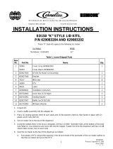
2. Position the Icemaker adapter lid on the Dispenser flush with the rear of the cabinet as shown in Figure 1.
3. Seal Icemaker to top of the Dispenser adapter lid as follows:
A. Locate the Icemaker flush with the rear of the lid and centered (for 24--1/2 inches wide Dispenser) as
shown in Figure 1. Run a bead of RTV on the lid inside the perimeter of the Icemaker base outline so
that the Icemaker will set on the RTV.

2
620917305
B. Set the Icemaker onto the lid. Note: If installing the Icemaker from front of the Dispenser, use a
length of 3/4--inch diameter or larger PVC pipe as a “roller” to slide the Icemaker over the front
“drip” flange of the Dispenser lid.
C. Wipe away any excess RTV.
4. Using the slotted holes in the adapter lid as a template, drill four (4) .147 diameter holes (No. 26 drill) into
the Dispenser cabinet (see detail A of Figure 1). Use extreme care not to drill into the ice storage bin.
Secure the lid to the Dispenser with four (4) No. 10 sheetmetal screws.
5. Install Icemaker mounting brackets two (2) as shown in Figure 1. Using the brackets as templates, drill
.147 inch diameter holes into the Icemaker cabinet and the adapter lid. Use extreme caution not to drill
into any Icemaker components (condenser, tubing, etc.). Secure the brackets to the Icemaker cabinet
with the No. 10 sheetmetal screws provided in the kit.
6. Follow the Icemakers Manufacturer’s instructions to complete installation of the Icemaker.
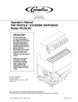
7. IMPORTANT: The bin thermostat bracket (item 7) must be installed (see Figure 2) in order to pre-
vent overfilling the ice storage bin
A. Remove the Icemaker front panel.
B. Locate the bin thermostat on the lower--right side wall of the ice drop area and remove the two (2)
thumbscrews that hold the bin thermostat in place.
C. Mount the bin thermostat to the bracket (item 7) provided with the kit as shown in Figure 2.
D. Using the thumbscrews from step B preceding, secure the “kit” bracket/bin thermostat assembly from
step C preceding to the same ice drop area position. The purpose of this “kit” bracket is to lower the
bin thermostat for proper filling of the ice storage bin.
E. Replace the Icemaker front panel.
8. Install the caution label (item 10) on the manual fill cover (item 2) and secure the cover to the adapter lid
with the No. 8--32 thumbscrew.
9. The Icemaker/Dispenser is ready for operation.
NOTE: Bin Thermostat must not interfere with the agitator rotation.

3
620917305
24--5/8 IN. 1--5/16 IN.
LID “B” DIM DIM C
ICEMAKER LOCATION
22 IN. FLUSH W/
SIDES OF LID
SEE DETAIL
“A”
SEAL ICEMAKER TO
ITEM 1 WITH ITEM 6 (RTV)
2--PLACES
2--PLACES
2
10
4
1
4
4
3
LOCATE ICEMAKER FLUSH
WITH REAR OF ADAPTER LID
AND CENTERED ON LID
ICEMAKER
5
22”
26.5 BASE
C
B
DRILL ø .147 HOLES
USING BOTTOM
OF SLOTTED HOLES
AS A TEMPLATE
DETAIL “A”
FIGURE 1.

4
620917305
ICEMAKER WITH FRONT
PANEL REMOVED
SEE DETAIL “A”
ADAPTER LID WITH
MANUAL FILL COVER
REMOVED
DETAIL “A”
ICEMAKER RIGHT
SIDE WALL
ICEMAKER BIN T’STAT
”THUMBSCREW”
8
7
9
ICEMAKER BIN T’STAT
WHITE PLASTIC
MOUNTING BRACKET
FIGURE 2.
/