Stairmaster HIITMill X 9-4640 Assembly Instructions

Type
Assembly Instructions

This manual is also suitable for

Stairmaster HIITMill X 9-4640 is a versatile fitness machine designed for high-intensity interval training. With its durable construction and various resistance levels, it offers challenging workouts for users of all fitness levels. The HIITMill X comes with pre-set programs and the ability to create custom workouts, allowing users to target specific fitness goals. Its compact design makes it suitable for home gyms or small fitness spaces, providing a convenient way to get a full-body workout.

Stairmaster HIITMill X 9-4640 is a versatile fitness machine designed for high-intensity interval training. With its durable construction and various resistance levels, it offers challenging workouts for users of all fitness levels. The HIITMill X comes with pre-set programs and the ability to create custom workouts, allowing users to target specific fitness goals. Its compact design makes it suitable for home gyms or small fitness spaces, providing a convenient way to get a full-body workout.

HIITMill & HIITMill X
ASSEMBLY INSTRUCTIONS
For Installation assistance or missing parts, please call CORE Health & Fitness at 1(800) 503-1221Document # 620-8596 Rev. C
PAGE 1 OF 2
STEP 1:
With a 5mm allen key, remove the two (2) screws and
washers securing the flywheel guard to the frame then slide the
user left side handrail between the frame and the flywheel guard.
CAUTION: Take care not to pinch or damage the brake cable when
installing. Feed any excess back into the frame and/or handrail.
STEP 2: Use a 5mm allen key to secure the flywheel guard to the
frame and user left side handrail using the screws and washers removed
in step one. DO NOT FULLY TIGHTEN YET. Once the flywheel guard is
secured, use a 6mm allen key to secure three (3) pieces each of the M10
x 25mm screws and M10 flat washers. DO NOT FULLY TIGHTEN YET.
STEP 3: Install the user right side handrail, use a 6mm
allen key to secure three (3) pieces each of the M10 x 25mm
screws and M10 flat washers. DO NOT FULLY TIGHTEN YET.
STEP 4: Install the main handlebar using a 5mm allen key to secure
four (4) pieces each of the M8 x 20mm screws, torque to 24Nm (18
Ft-Lb). Secure left and right side beauty rings using a 2.5mm allen key
and one (1) piece each of the M4 x 8mm screws, torque to 4Nm (3
Ft-Lb). Once the main handlebar is secure to the user left and right side
handrails, tighten the hardware in steps 1-3 to 48Nm (35Ft-Lb).
NOTE: the weight carry arms are available on the HIITMill X only.
STEP 5: (HIITMill ONLY) Install the user right “U”
shaped rear handrail, use a 5mm allen key to secure 3
pieces of the M8 x 20mm screws, torque to 24Nm (18
Ft-Lb). Repeat for the user left rear handrail.
STEP 6: On the HIITMill X, install the user right side weight horn,
using a 5mm allen key and an open/box end wrench to secure 2
pieces each of the M8 x 75mm bolt and M8 hex lock nut, torque to
24Nm (18 Ft-Lb). Repeat for the user left side weight horn.
PINCH WARNING
HIITMill & HIITMill X
ASSEMBLY INSTRUCTIONS
For Installation assistance or missing parts, please call CORE Health & Fitness at 1(800) 503-1221Document # 620-8596 Rev. C
PAGE 2 OF 2
STEP 2:
Use a 3mm allen key to secure the HIIT
Console to the mount using four (4) M5 x 14mm screws.
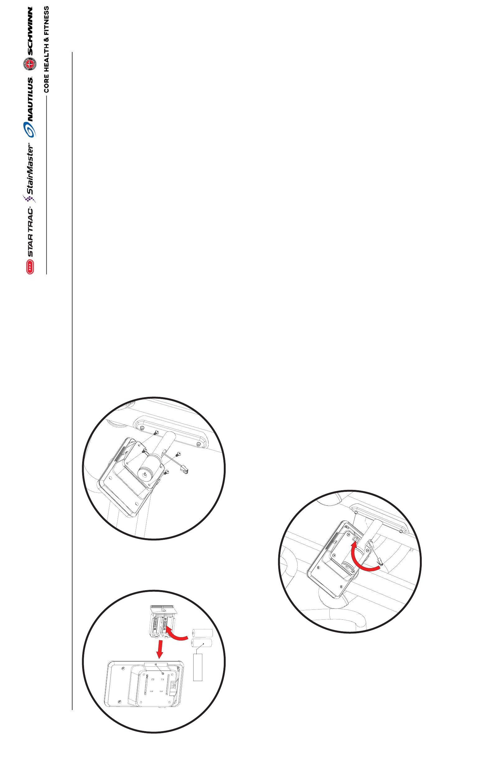
STEP 3: Connect the main data cable to the console.
STEP 4: After installing the console, ensure that the unit type
is set for the appropriate model:
1. Power the console on by pressing the counter-clockwise
arrow.
2. Press and hold the arrow up, arrow down, and clock
buttons at the same time for 3-5 seconds.
3. Verify that the “tread” software is selected. To do this, use
the down arrow to navigate to the 4th page and press the
clock button to change between the following:
P1 “tread” - HIITMill and HIITMill X
P2 “bic1” - HIIT Bike
P3 “ergo” - HIIT UBE
P4 "Step" - Not Used Currently
P5 “bic2” - Airfit Bike
P6 none - Not Used Currently
4. Press the back button located between the up/down arrow
buttons to return to the main workout screen once “P1 -
tread” has been selected.
STEP 5: Calibrating HIITMill (X) Power Sensor:
Before using the HIITMill with the HIIT Console installed, the
power sensor must be calibrated. If the sensor is not calibrat-
ed before using the unit, the console will display inaccurate
workout data. The calibration should only need to be done
during the first setup. The calibration can also be done to
correct any perceived issues with the workout data not being
accurate.
1. Push the brake adjustment lever all the way forward (away
from the user).
2. Press and hold the arrow up, arrow down, and clock
buttons at the same time for 3-5 seconds.
3. Use the down arrow to navigate to page 7, then push the
clock button to set the zero-point angle.
4. Press the back button located between the up/down arrow
buttons to return to the main workout screen.
LR14 1.5V
STEP 1: Use a #2 phillips screwdriver to remove the
locking screw securing the battery drawer inside
the console. Remove the battery drawer then install two
(2) LR14 1.5V batteries into the drawer. Finally, reinsert
the battery drawer and reinstall the locking screw.
  • Page 1 1
  • Page 2 2

Stairmaster HIITMill X 9-4640 Assembly Instructions

Type
Assembly Instructions
This manual is also suitable for

Stairmaster HIITMill X 9-4640 is a versatile fitness machine designed for high-intensity interval training. With its durable construction and various resistance levels, it offers challenging workouts for users of all fitness levels. The HIITMill X comes with pre-set programs and the ability to create custom workouts, allowing users to target specific fitness goals. Its compact design makes it suitable for home gyms or small fitness spaces, providing a convenient way to get a full-body workout.

Ask a question and I''ll find the answer in the document

Finding information in a document is now easier with AI