Page is loading ...

LZR
®
-FLATSCAN REV-LZ
E
R
L
A
U
B
T
Z
E
R
T
I
F
I
Z
I
E
R
U
N
G
N
A
C
H
EN 16005
E
N
A
B
L
E
S
A
C
C
O
R
D
A
N
C
E
W
I
T
H
E
R
L
A
U
B
T
Z
E
R
T
I
F
I
Z
I
E
R
U
N
G
N
A
C
H
DIN 18650
E
N
A
B
L
E
S
A
C
C
O
R
D
A
N
C
E
W
I
T
H
EN
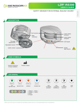
SAFETY SENSOR FOR REVOLVING DOORS
User’s Guide for software version 0202 and higher
(refer to tracking label on product)

2
INSTALLATION TIPS
When needed, wipe
the laser window only
with a soft, clean and
damp microfibre cloth.
Do not use dry or dirty
towels or aggressive
products to clean the
laser window.
• The device cannot be used for purposes other than its intended use. All other uses cannot be
guaranteed by the manufacturer of the sensor.
• The manufacturer of the door system is responsible for carrying out a risk assessment and installing the
sensor and the door system in compliance with applicable national and international regulations and
standards on door safety.
• The manufacturer of the sensor cannot be held responsible for incorrect installations or inappropriate
adjustments of the sensor.
Only trained and
qualified personnel may
install and setup the
sensor.
The warranty is invalid if
unauthorized repairs are
made or attempted by
unauthorized personnel.
Always test the good
functioning of the
installation before leaving
the premises.
The door control unit
and the door cover
profile must be correctly
earthed.
MAINTENANCE TIPS
SAFETY TIPS
Avoid vibrations. Do not cover
the laser window.
Avoid moving objects
and light sources in
the detection field.
Avoid the presence
of smoke and fog in
the detection field.
Avoid condensation. Avoid exposure to
sudden and extreme
temperature changes.
Keep the sensor permanently
powered in environments
where the temperature can
descend below -10°C.
Avoid direct exposure
to high pressure
cleaning.
Remove the laser window
protection before
the teach-in and the
commissioning of the
sensor.
Do not remove the laser
window protection if
building works are still
in progress on site.

3
x
2
1
5
4
7
16
3
13
12
9
14
15
11
8
17
6
10
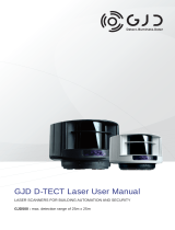
The LZR
®
-FLATSCAN REV-LZ is a protective sensor for revolving doors based on laser technology.
It detects the test body CA (acc. to EN 16005) in the area in front of the door wing. To do so, a
module must be installed in the upper corner of each door leaf. Other protective equipment might
be necessary in order to achieve compliance with 5.9.3 of EN 16005, depending on the analysis
conducted by the door manufacturer.
LED-SIGNALS
DESCRIPTION
1. cover
2. push button
3. DIP-switch
4. spare connector (not used)
5. connector
6. angle adjustment screw
7. plug
8. clamp
9. cap and screws (flexible kit)
10. flexible tube
11. lock screw
12. laser head
Relay 2
Relay 1
LED flashes
LED flashes
slowly
LED is off
LED flashes
x times
LED flashes
red-green
LED flashes
quickly
Calculation in progress
Exit the zone and wait
13. laser window
14. laser window protection
15. positioning aids
16. mounting base
17. power cable

4
1 2
3 4
1
MOUNTING ON DOOR
Slide the base off the sensor module.
Take the base and put it on the door frame.
The positioning aids help you to align the base correctly.
When mounting the base, make sure the sensor will not hinder the door movement.
Using a pencil, mark the position of the holes
to drill into the door frame. You can also use the inner
surface of the base to fasten the screws.
Remove the base and pre-drill the holes where marked.

5
Ø 10 mm
2
4
5 6
1
3
Ø 10 mm
1a
HIDE CABLE INSIDE THE SENSOR
Using a wire cutter, remove the positioning aids from
the base.
Fasten the 3 screws using a Pozidrive screwdriver.
The base needs to be fixed firmly!
Drill through the base and the door using a 10 mm bit
in order to pass the cable.
Soften the edges using a sheet of sandpaper.
Take the cable and pass it through the hole. Position
the cable in the notch of the base and make sure it is
firmly fixed.
Take the sensor and remove the cover: put your
finger in the hole and pull firmly towards you in one
movement.
Pass the cable through the hole on the back of the
sensor and fasten the sensor on the base by sliding it
downwards.
We provide two cabling modes (1a or 1b), please process following steps according to the site condition.

6
1b
«click»
5 6
7 8
1 2
EXTEND CABLE OUTSIDE THE SENSOR
Connect the plug to the white connector. Make sure that all wires are safely tucked within the
notch to avoid crushing them with the cover.
Close the sensor which will not be connected to the
door controller using a plug.
Fasten the lock screw firmly.
Take the flexible tube and determine how long it
should be in order to reach the door controller.
Cut the surplus to avoid undesired detections caused
by the flexible tube.

7
3
4
5
6
+
-
12-24 V DC
COM
NC
*
COM
NC
*
R1
R2
2
Cut the power cable to the right length, strip the 8 wires and connect all wires as indicated.
The polarity of the power supply is important.
For compliance with EN 16005 and DIN 18650, the door controller test output must be connected and activated to
test the sensor.
* Output status when sensor is operational.
Pass the power cable through the flexible tube.
Connect the plug to the white connector.
Make a loop with the wires of the power cable and
pass them through the notch as indicated.
Use the other part of the cable to block the wires.
Take the clamp to fix the flexible tube to the sensor.
Fasten the 2 screws firmly in order to avoid pulling out
the cable.
Tighten the other side of the flexible tube using the
cable cap and pass through the rest of the power
cable towards the door controller.
POWER SUPPLY
TEST
OUTPUT 1
OUTPUT 2
GREEN
BROWN
YELLOW
WHITE
PINK
GREY
RED
BLUE
WIRING

8
3
ON
1 2 3 4
ON
1 2 3 4
ON
OFF
4
1.
X
Custom Mode
Standard Mode
TEACH-IN PROCESS
DIP-SWITCH 1
Before launching a teach-in, make sure that:
- glass surfaces near the door are covered
- the door controller is set up first
- the detection field is free of snow buildups, heavy rain, snowfall, fog or other objects or people
- the laser window protection is removed.
1. To launch a teach-in, press the push button briefly. The LED starts to flash red-green quickly.
2. Wait until sensor flashes green quickly. Position yourself in front of the door and stretch out your arm in front
of you. Make an up and down movement in front of the moving edge level in order to mark the limit of the
detection zones. The LED flashes red while calculating the width of the door wings.
3. • Standard Mode*:
The LED starts to flash red, then green slowly, next the red, no need to do anything during
this process ( Make sure you’re outside of the detection field ), wait until the LED is off, the teach-in is completed.
• Custom Mode: The LED starts to flash red, then green slowly, then move your hand to define the detection
field as your request, next LED flashes red. ( Make sure you’re outside of the detection field ), wait until the LED is
off, the teach-in is completed.
Make sure the setting of DIP 1 is correct.
Output from R1,
red LED
flashes
when there is a detection.
(Recommended Mode)
Output from R2,
green LED
flashes when there is a detection.
< 1 sec.
2. FIELD WIDTH 3. TEACH-IN
TEACH-IN
30s
30s
ORANGE OFF
After changing a DIP-switch, the orange LED flashes.
A LONG push on the push button confirms the settings.
GREEN
> 3 sec.
FACTORY VALUE
* The default mode is Standard Mode.
A
rectangle shape
can be traced in the detection area during the learning
process of 30 seconds.
A
custom shape
can be traced in the detection area during the learning
process of 30 seconds.

9
B
A
B
A
5
PZ1
6
«click»
TESTING AND ADJUSTING
Check the correct positioning of the
safety fields by placing an object in
the detection field.
After changing the angle, the sensor position or the environment, always launch a teach-in and test the correct
positioning of the detection fields.
Close the cover starting on the narrow
side (1). Do not hesitate to push.
To open the sensor again, position a screwdriver in the
notch and pull upwards until the cover comes loose.
FINAL STEPS
If necessary, adjust the tilt angle of the laser curtain by turning the
tilt angle adjustment screw (from 2° to 10°).
The service mode deactivates the safety detection during 15 minutes and can be
useful during an installation, a mechanical teach-in of the door or maintenance
work.
To enter the service mode, push on the button for at least 3 seconds.
When the sensor is in service mode, the LED is off.
To exit the service mode, push again for at least 3 seconds.
The service mode is deactivated automatically when launching a teach-in.
SERVICE MODE
> 3 sec.
«click»

10
D
C
NO
NC
NC
NO
NO
NO
NC
NC
R1
R2
X
1 2 3 4
ON OFF
NO NC
ON
ON
OFF
NC NO
cm001 - 400
cm001 - 400
FACTORY VALUE
REMOTE CONTROL SETTINGS (OPTIONAL)
no field
DIMENSIONS
DOOR WING SAFETY
no field
A teach-in overwrites these values automatically.
OUTPUT
CONFIGURATION
NO = normally open NC = normally closed
NO POWER
NO DETECTION
DETECTION
DIP-SWITCH SETTINGS (OPTIONAL)
After changing a DIP-switch, the orange LED flashes. A LONG push on the push
button confirms the settings.
ORANGE OFFGREEN
In order to change these settings by remote control, adjust DIP-switch 4 to ON
Switch to CRITICAL when external disturbances
are likely to cause unwanted detections
(min. obj. size, immunity and uncovered zone are increased).
Switch to OFF when there is no background
(glass floor, footbridge...).
Switch to NO when the door controller requires it.
DIP 4 OUTPUT CONFIGURATION
DIP 3 BACKGROUND
DIP 2 ENVIRONMENT
standard critical

11
*
cm
2 4 6
8
10
12 14
16 18
E
R
L
A
U
B
T
Z
E
R
T
I
F
I
Z
I
E
R
U
N
G
N
A
C
H
EN 16005
E
N
A
B
L
E
S
A
C
C
O
R
D
A
N
C
E
W
I
T
H
OFF
OFF
OFF
ON
ON
ON
> > > > > > >
ON
OFF
FACTORY VALUE
full resetteach-in
partial reset
Factory reset
of all values
Factory reset
of all values exept field
dimensions and
output configurations
See page 8
UNCOVERED ZONE
Increase in case of snow, dead leaves, etc.
* Measured in specific conditions and dependant on application and installation.
ANTIMASKING &
BACKGROUND
GENERAL
ANTIMASKING
BACKGROUND
Antimasking: protective function which detects an unwanted object nearby the laser
window masking the vision field.
Background: reference point in the detection field of the sensor.
If no background is present, switch to off.
IMMUNITY FILTER
Increase to filter out external disturbances.
The reaction time increases significantly between value 5 and 9.
low high
Switch to CRITICAL when external disturbances
are likely to cause unwanted detections
(min. obj. size, immunity and uncovered zone are increased).
In order to change these settings by remote control, adjust DIP-switch 2 to ON
In order to change these settings by remote control, adjust DIP-switch 3 to ON
In order to change these settings by remote control, adjust DIP-switch 2 to ON

12
2x 3x
1x
x
5x
1x
HOW TO USE THE REMOTE CONTROL
ADJUSTING ONE OR MORE PARAMETERS
CHECKING A VALUE
RESTORING TO FACTORY VALUES
SAVING AN ACCESS CODE
DELETING AN ACCESS CODE
The access code is recommended for sensors installed close to each other.
After unlocking, the red
LED flashes and the sensor
can be adjusted by remote
control.
If the red LED flashes quickly after unlocking, you
need to enter an access code from 1 to 4 digits.
If you do not know the access code, cut and restore
the power supply. During 1 minute, you can access
the sensor without introducing any access code.
= field width: 2.35 m
To end an adjustment session,
always lock the sensor.
Enter the existing code
x = number of flashes = value of the parameter
full reset
partial reset
It is recommended to use a different access code for each module in order to avoid changing settings on
multiple modules at the same time.

13
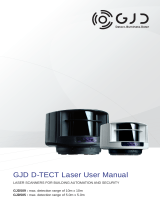
TWO-WING REVOLVING DOOR THREE-WING REVOLVING DOOR
DETECTION FIELDS
DOOR WING SAFETY
Typ. object size: 10 cm at 4 m
UNCOVERED ZONE
Adjustable by remote control
Factory value: 10 cm

14
TROUBLESHOOTING
In case of unwanted reactions of the door, verify whether the problem is caused by the sensor, or the door controller.
To do so, activate the service mode (no safety) and launch a door cycle.
If the door cycle is completed successfully, check the sensor. If not, verify the door controller, the wiring or other sensor.
The RED or GREEN LED
is ON sporadically or
permanently and the door
does not react
as expected.
Bad teach-in Launch a new teach-in.
Unwanted detections
(due to environment or
external conditions)
1
Make sure the flexible cable does not cause
detections.
2
Verify if the laser window is dirty and clean it with
compressed air. Then wipe it carefully with a damp
and clean microfibre cloth if necessary.
(attention: the surface of the laser window is delicate)
3 Launch a new teach-in.
4 Switch DIP 2 to off (critical environment).
The sensor does not react
at power-on.
Inverted power supply
Check wiring (green +, brown -).
Faulty cable
Replace cable
Faulty sensor Replace sensor
The sensor does not react
when powered.
Test error Check voltage between red and blue wires.
The service mode is activated Press the push button during at least 3 seconds
to exit the service mode.
It is not possible to
adjust a setting by remote
control.
Wrong DIP-switch position. Adjust the required DIP-switches to ON.
The remote control does
not react.
The sensor is protected by a
password.
Enter the right password. If you forgot the code, cut
and restore the power supply to access the sensor
without entering a password during 1 minute.

15
2
1
3
4
5
The ORANGE LED is on
permanently.
The sensor encounters a
memory problem.
Send the sensor back for a technical check-up.
The ORANGE LED flashes
quickly.
DIP-switch setting awaiting
confirmation.
Corfirm the DIP-switch setting: long push on the push
button.
The ORANGE LED flashes
1 x every 3 seconds.
The sensor signals an
internal fault.
Cut and restore power supply.
LED flashes again, replace sensor.
The ORANGE LED flashes
2 x every 3 seconds.
Power supply is out of limit.
1
Check power supply (voltage, capacity).
2
Reduce the cable length or change cable.
Internal temperature is too
high.
Protect the sensor from any heat source (sun, hot
air...)
The ORANGE LED flashes
3 x every 3 seconds.
Communication error between
modules.
1
Check wiring between interface card and laser head.
The ORANGE LED flashes
4 x every 3 seconds.
The sensor does not see its
background.
Switch DIP 3 to off (deactivates background).
Something close to the sensor
is masking part of the detec-
tion field.
1
Make sure the laser window is not scratched.
If it is, replace sensor.
2
Remove all masking elements (insects, spider web,
flexible tube, window protection).
3
Verify if the laser window is dirty and clean it with
compressed air. Then wipe it carefully with a damp
and clean microfibre cloth if necessary
(attention: the surface of the laser window is delicate)
4
Switch antimasking setting to off (attention: no
conformity to DIN 18650 or EN 16005).
The ORANGE LED flashes
5 x every 3 seconds.
Teach-in error.
1
Check whether all teach-in requirements are fulfilled
(see page 8) and launch a new teach-in.
2
Adjust the tilt angle of the laser curtain and launch a
new teach-in.
3 Adjust the field dimensions by remote control.

BEA SA | LIEGE Science Park | ALLÉE DES NOISETIERS 5 - 4031 ANGLEUR [BELGIUM] | T +32 4 361 65 65 | F +32 4 361 28 58 | E [email protected] | www.beasensors.com
©BEA | Original instructions | 47.0355 / V2 - 05.20
TECHNICAL SPECIFICATIONS
Technology LASER scanner, time-of-flight measurement
Detection mode Presence
Max. detection range 4 m (diagonal) with reflectivity of 2% (i.e.: at W = 1.5m -> max. H = 3.7 m)
Opening angle 90°
Angular resolution 1.3°
Typ. min. object size 10 cm @ 4m (in proportion to object distance, DIP 2 = ON)
Testbody 700 mm × 300 mm × 200 mm (testbody CA according to EN 16005 & DIN 18650-1)
Emission characteristics
IR LASER: wavelength 905 nm; output power < 0.1 mW; CLASS 1
(IEC/EN 60825)
Supply voltage
12 - 24 V DC ± 15 %
(The Equipment must be powered by an approved Class II SELV limited
power source. This requirement consists of the need for double insulation between primary
voltages and the Equipment supply)
Power consumption ≤ 2 W
Response time 50 ms
Output
Max. switching voltage
Max. switching current
2 electronic relays (galvanic isolation - polarity free)
42V AC/DC
100 mA
LED-signals 1 bi-coloured LED: detection/output status
Dimensions 142 mm (L) × 85 mm (H) × 33 mm (D) ( mounting base + 7 mm )
Material - Colour PC/ASA - Black - Aluminum - White
Tilt angles +2° to +10° (without mounting base)
Protection degree IP54 (IEC/EN 60529)
Temperature range -30°C to +60°C if powered
Humidity 0-95 % non-condensing
Vibrations
< 2 G
Compliance EN 16005 (test body CA)
DIN 18650-1 (test body CA)
EN 12978
EN ISO 13849-1 PL “d” / CAT2
IEC/EN 60825-1
IEC/EN 61508 SIL2
Specifications are subject to change without prior notice. All values are measured in specific conditions
.
BEA hereby declares that the equipment type LZR
®
-FLATSCAN REV LZ is in compliance with European Directives
2006/42/EC (Machinery), 2011/65/EU (RoHS) and 2014/30/EU (EMC).
Notified Body for EC inspection: 0044 - TÜV NORD CERT GmbH, Langemarckstr. 20, D-45141 Essen.
EC-type examination certificate number: 44 205 13089633 Estelle Graas, Angleur, July 2019
The complete declaration of conformity is available on our website.
This product should be disposed of separately from unsorted municipal waste.
Please keep for further use - Designed for colour printing
/