o]
®
Home Appliances
WARNING: If the information in these
instructions is not followed exactly, a fire
or explosion may result causing property
damage, personal injury or death.
Do not store or use gasoline or other
flammable vapors and liquids in the
vicinity of this or any other appliance.
WHAT TO DO IF YOU SMELL GAS
• Do not try to light any appliance.
• Do not touch any electrical switch;
do not use any phone in your
building.
• Immediately call your gas supplier
from a neighbor's phone. Follow
the gas supplier's instructions.
• If you cannot reach your gas
supplier, call the fire department.
Installation and service must be performed
by a qualified installer, service agency or
the gas supplier.
INSTALLER:
• AFFIX THESE INSTRUCTIONS TO OR ADJACENT
TO THE WATER HEATER.
OWNER:
• RETAIN THESE INSTRUCTIONS AND WARRANTY
FOR FUTURE REFERENCE. RETAIN THE ORIGINAL
RECEIPT AS PROOF OF PURCHASE.
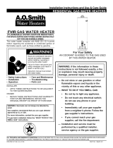
Ultra Low Nox
Gas Water Heater
with the Flame Lock®
Safety System
Installation
Instructions and
Use & Care Guide
To obtain technical, warranty, or service assistance during or after
the installation of this water heater, visit our website at:
http://www.whirlpoolwaterheatersupport.com
or call toll free
1-877-817-6750
When calling for assistance, please have the following
information ready:
1. Model number
2. 7 digit product number
3. Serial number
4. Date of installation
5. Place of purchase
Table of Contents ...................................................... 2
319118-002
October 2010

WATER HEATER SAFETY
Your safety and the safety of others are very important.
We have provided many important safety messages in this manual and on your appliance. Always read and obey all
safety messages.
This is the safety alert symbol.
This symbol alerts you to potential hazards that can kill or hurt you and others.
All safety messages will follow the safety alert symbol and either the word "DANGER" or
"WARNING." These words mean:
You can be killed or seriously injured if you don't
immediately follow instructions.
You can be killed or seriously injured if you don't
follow instructions.
All safety messages will tell you what the potential hazard is, tell you how to reduce the chance of injury, and tell you
what can happen if the instructions are not followed.
Important Instructions
Do not use this appliance if any part has been under water. Immediately call a qualified person. Water heaters sub-
jected to flood conditions or any time the gas controls, main burner or pilot have been submerged in water require
replacement of the entire water heater.
Hydrogen gas can be produced in a hot water system that has not been used for a long period of time (generally
two weeks or more). Hydroqen qas is extremely flammable and can ignite when exposed to a spark or flame. To
prevent the possibility of injury under these conditions, we recommend the hot water faucet be opened for several
minutes at the kitchen sink before using any electrical appliance which is connected to the hot water system. If
hydrogen is present, there will probably be an unusual sound such as air escaping through the faucet as water
begins to flow. Do not smoke or have any open flame near the faucet at the time it is open.
The California Safe Drinking Water and Toxic Enforcement Act requires the Governor of California to publish a list of
substances known to the State of California to cause cancer, birth defects, or other reproductive harm, and requires
businesses to warn of potential exposure to such substances.
WARNING: This product contains a chemical known to the State of California to cause cancer, birth defects, or other
reproductive harm.
This appliance can cause low-level exposure to some of the substances included in the Act.
2
Table Of Contents PAGE
Water Heater Safety .............................................................................. 1-2
InstallingYour Gas Water Heater ........................................................ 3-16
Unpacking the Water Heater ........................................................... 3
Location Requirements ................................................................ 4-5
Gas Supply .................................................................................. 6-7
Combustion Air Supply and Ventilation ...................................... 7-11
Water System Piping ............................................................... 12-13
Temperature & Pressure Relief Valve ........................................... 14
Special Applications ...................................................................... 15
Installation Checklist ..................................................................... 16
Operating Your Water Heater ............................................................ 17-21
Lighting Instructions...................................................................... 17
Operating the Temperature Control System ................................. 20
Operational Conditions ................................................................. 21
Maintenance ofYour Water Heater ................................................... 22-26
Troubleshooting Charts ..................................................................... 26-29
Repair Parts Illustration..................................................................... 30-31

INSTALLING YOUR GAS WATER HEATER
Important Information About
This Water Heater
This gas water heater was manufactured to voluntary
safety standards to reduce the likelihood of a flammable
vapor ignition incident. New technology used in meeting
these standards makes this product more sensitive to
installation errors or improper installation environments.
Please review the Installation Checklist found at the end of
the installation instructions section and make any required
installation upgrades or changes.
Consumer Information
This water heater is design-certified by CSA International
as a Category I, non-direct vented water heater which takes
its combustion air either from the installation area or from
air ducted to the unit from the outside.
This water heater must be installed according to all local
and state codes or, in the absence of local and state codes,
the "National Fuel Gas Code", ANSI Z223.1(NFPA 54)-
current edition. This is available from the following:
CSA America, Inc.
8501 East Pleasant Valley Road
Cleveland, OH 44131
National Fire Protection Association
1 Batterymarch Park
Quincy, MA 02269
Check your phone listings for the local authorities having
jurisdiction over your installation.
Consumer Responsibilities
This manual has been prepared to acquaint you with the
installation, operation, and maintenance of your gas water
heater and provide important safety information in these
areas.
Read all of the instructions thoroughly before attempting
the installation or operation of this water heater.
Do not discard this manual. You or future users of this
water heater will need it for future reference.
Service to the Flame Lock®Safety System should only be
performed by a qualified person.
Examples of a qualified person include: licensed plumbers,
authorized gas company personnel, and authorized
service personnel.
IMPORTANT: The manufacturer and seller of this water
heater will not be liable for any damages, injuries, or
deaths caused by failure to comply with the installation and
operating instructions outlined in this manual.
If you lack the necessary skills required to properly install
this water heater, or you have difficulty following the
instructions, you should not proceed but have a qualified
person perform the installation of this water heater.
Massachusetts code requires this water heater to be
installed in accordance with Massachusetts Plumbing and
Fuel Gas Code 248 CMR Section 2.00 and 5.00.
A data plate identifying your water heater can be found next
to the gas control valve/thermostat. When referring to your
water heater, always have the information listed on the data
plate readily available.
Retain your original receipt as proof of purchase.
Unpacking the Water Heater
Excessive Weight Hazard
Use two or more people to move and install
water heater.
Failure to do so can result in back or
other injury.
IMPORTANT: Do not remove any permanent instructions,
labels, or the data label from either the outside of the water
heater or on the inside of water heater panels.
• Remove exterior packaging and place installation com-
ponents aside.
• Inspect all parts for damage prior to installation and
start-up.
• Completely read all instructions before attempting to
assemble and install this product.
• After installation, dispose of/recycle all packaging
materials.

Flammable Vapors
FIRE AND EXPLOSION HAZARD
Can result in serious injury or death
_Do not store or use gasoline or other
flammable vapors and liquids in the
vicinity of this or any other appliance.
Storage of or use of gasoline or other
flammable vapors or liquids in the vicinity
of this or any other appliance can result in
serious injury or death.
Read and follow water heater warnings and
instructions.
Location Requirements
Carbon Monoxide Poisoning Hazard
Do not install in a mobile home.
Doing so can result in death or
carbon monoxide poisoning.
The Flame Lock®Safety System is designed to reduce the
risk of flammable vapor-related fires. The patented system
protects your family by trapping the burning vapors within
the water heater combustion chamber through the special
flame-trap. The burning vapors literally "burn themselves
out" without escaping back into the room. In the event of a
flammable vapor incident, the Flame Lock ®Safety System
disables the water heater by shutting off the gas supply to
the water heater's burner and pilot, preventing re-ignition of
any remaining flammable vapors in the area. This will not
prevent a possible fire/explosion if the igniter is depressed
and flammable vapors have accumulated in the combustion
chamber with the pilot light off. If you suspect a flammable
vapor incident has occurred, do not use this appliance. Do
not attempt to light this appliance, or depress the igniter
button if you suspect flammable vapors have accumulated
inside or outside the appliance. Immediately call a qualified
person to inspect the appliance. Water heaters subjected
to a flammable vapors incident will show a discoloration on
the flame-trap and require replacement of the entire water
4
heater. Note: Not following these instructions and/or an
inadequate air supply can cause the Flame Lock®Safety
System to disable the water heater. Please make required
installation and venting/air supply changes prior to resetting
the system (see "Combustion Air Supply and Ventilation"
section).
Do not use or store flammable products such as gasoline,
solvents, or adhesives in the same room or area near the
water heater. If such flammables must be used, all gas
burning appliances in the vicinity must be shut off and their
pilot lights extinguished. Open the doors and windows for
ventilation while flammable substances are in use.
If flammable liquids or vapors have spilled or leaked in the
area of the water heater, leave the area immediately and
call the fire department from a neighbor's home. Do not
attempt to clean the spill until all ignition sources have been
extinguished.
Keep combustibles such as boxes, magazines, clothes,
etc. away from the water heater area.
Site Location
Select a location near the center of the water piping
system. The water heater must be installed indoors and
in a vertical position on a level surface. Do not install in
bathrooms, bedrooms, or any occupied room normally
kept closed.
Locate the water heater as close to the chimney or gas
vent as practical. Consider the vent system piping and
combustion air supply requirements when selecting the
water heater location. The venting system must be able
to run from the water heater to termination with minimal
length and elbows.
• Locate the water heater near the existing gas piping.
If installing a new gas line, locate the water heater to
minimize the pipe length and elbows.
NOTE: This water heater must be installed according to all
local and state codes or, in the absence of local and state
codes, the "National Fuel Gas Code", ANSI Z223.1 (NFPA
54)-current edition.

IMPORTANT:Thewaterheatershouldbelocated
inanareawhereleakageofthetankorconnections
willnotresultindamagetotheareaadjacenttothe
waterheaterortolowerfloorsofthestructure.Due
tothenormalcorrosiveactionofthewater,thetank
willeventuallyleakafteranextendedperiodoftime.
Alsoanyexternalplumbingleak,includingthosefrom
improperinstallation,maycauseearlyfailureofthetank
duetocorrosionifnotrepaired.Ifthehomeowneris
uncomfortablewithmakingtherepairaqualifiedperson
shouldbecontacted.Asuitablemetaldrainpanshould
beinstalledunderthewaterheaterasshownbelow,
tohelpprotectthepropertyfromdamagewhichmay
occurfromcondensateformationorleaksinthepiping
connectionsortank.Thepanmustlimitthewaterlevel
toamaximumdepthof1-3/4"andbetwoincheswider
thantheheaterandpipedtoanadequatedrain.
NOTE:Thepanmustnotrestrictcombustionairflow.
Locatethewaterheaternearanadequateindoordrain.
Thedischargepipemustterminateamaximumofsix
inchesaboveafloordrainorexternaltothebuilding.In
coldclimates,itisrecommendedthatthedischargepipe
beterminatedatanadequatedraininsidethebuilding.
Outsidedrainsaresubjecttofreezingtemperatures
whichcanobstructthedrainline.Thepipingshouldbe
atleast3/4"IDandpitchedforproperdrainage.Under
nocircumstanceswillthemanufacturerorsellerofthis
waterheaterbeheldliableforanywaterdamagewhich
iscausedbyyourfailuretofollowtheseinstructions.
Figure 1 DISCHARGEPIPE
Drain Pan Installation DONOT CAP ORPLUG)
METAL
DRAIN
PANI !,,,MAXIMUM
'_ _ © © AIR GAP
_ AT LEAST 2" GREATER THAN THE I i_ ""_ /
DIAMETER OF THE WATER HEATER. PIPED TO AN
ADEQUATE DRAIN
• The water heater should be located in an area not
subject to freezing temperatures. Water heaters located
in unconditioned spaces (i.e., attics, basements,
etc.) may require insulation of the water piping and
drain piping to protect against freezing. The drain and
controls must be easily accessible for operation and
service. Maintain proper clearances as specified on the
data plate.
• Do not locate the water heater near an air-moving
device. The operation of air-moving devices such as
exhaust fans, ventilation systems, clothes dryers,
fireplaces, etc., can affect the proper operation of
the water heater. Special attention must be given to
conditions these devices may create. Flow reversal of
flue gases may cause an increase of carbon monoxide
inside of the dwelling.
• If the water heater is located in an area that is
subjected to lint, dirt, and oil, it may be necessary
to periodically clean the flame-trap (see "External
Inspection & Cleaning of the Flame-trap" section).
Figure 1A
Air-moving
Devices
Exhaust
Fan
/
i! Reverse flow
of gases
Clearances and Accessibility
NOTE: Minimum clearances from combustible surfaces are
stated on the data plate adjacent to the gas control valve/
thermostat of the water heater.
The water heater is certified for installation on a
combustible floor.
• IMPORTANT: If installing over carpeting, the carpeting
must be protected by a metal or wood panel beneath
the water heater. The protective panel must extend
beyond the full width and depth of the water heater by
at least three inches (76.2mm) in any direction; or if in
an alcove or closet installation, the entire floor must be
covered by the panel.
• Figure 2 may be used as a reference guide to locate
the specific clearance locations. A minimum of 24
inches of front clearance should be provided for
inspection and service.
Figure 2
Minimum Clearance
Locations
Top
v/--Back Sides to ._IE_
____F io_t irniicmu ceilin
c::=__ m Side_ll I
III
Top T
View
_Vent
State of California
NOTE: The water heater must be braced, anchored, or
strapped to avoid moving during an earthquake.
Contact local utilities for code requirements in your area,
visit http://www.dsa.dgs.ca.gov, or call 1-916-445-8100 and
request instructions.

Gas Supply
Explosion Hazard
Use a new CSA approved gas supply line.
Install a shut-off valve.
Do not connect a natural gas water heater to
an L.P. gas supply.
Do not connect an L.P. gas water heater to
a natural gas supply.
Failure to follow these instructions can
result in death, explosion, or
carbon monoxide poisoning.
Gas Requirements
IMPORTANT: Read the data plate to be sure the water
heater is made for the type of gas you will be using in
your home. This information will be found on the data
plate located near the gas control valve/thermostat. If the
information does not agree with the type of gas available,
do not install or light. Call your dealer.
NOTE: An odorant is added by the gas supplier to the gas
used by this water heater. This odorant may fade over an
extended period of time. Do not depend upon this odorant
as an indication of leaking gas.
Gas Piping
The gas piping must be installed according to all local and state
codes or, in the absence of local and state codes, the "National
Fuel Gas Code",ANSI Z223.1 (NFPA 54)-current edition.
Table 1on page 7 provides a sizing reference for commonly
used gas pipe materials. Consult the "National Fuel Gas Code"
for the recommended gas pipe size of other materials.
Refer to Figure 3
NOTE: When installing gas piping, apply approved pipe joint
compound.
1. Install a readily accessible manual shut-off valve in the
gas supply line as recommended by the local utility.
Know the location of this valve and how to turn off the
gas to this unit.
2. Install a drip leg (if not already incorporated as part of
the water heater) as shown. The drip leg must be no
less than three inches long for the accumulation of dirt,
foreign material, and water droplets.
3. Install a ground joint union between the gas control
valve/thermostat and the manual shut-off valve. This
is to allow easy removal of the gas control valve/
thermostat.
4. Turn the gas supply on and check for leaks. Test all
connections by brushing on an approved noncorrosive
leak-detection solution. Bubbles will show a leak.
Correct any leak found.
Figure 3
Gas Piping
Manual Gas
Shut-off Valve'---._
Ground
Joint
Union
Check with local
utility for
minimum height _3"M
i
Drip Leg
v
Gas Pressure
IMPORTANT: The gas supply pressure must not exceed the
maximum supply pressure as stated on the water heater's data
plate. The minimum supply pressure is for the purpose of input
adjustment.
Gas Pressure Testing
IMPORTANT: This water heater and its gas connection must
be leak tested before placing the appliance in operation.
• If the code requires the gas lines to be tested at a pressure
exceeding 14"W.C., the water heater and its manual shut-
off valve must be disconnected from the gas supply piping
system and the line capped.
• If the gas lines are to be tested at a pressure less than
14"W.C., the water heater must be isolated from the gas
supply piping system by closing its manual shut-off valve.
U.L. recognized fuel gas and carbon monoxide (CO) detectors
are recommended in all applications and should be installed
using the manufacturer's instructions and local codes, rules, or
regulations.
NOTE: Air may be present in the gas lines and could prevent
the pilot from lighting on initial start-up. The gas lines should
be purged of air by a qualified person after installation of the
gas piping system. While purging the gas piping system of air,
make sure that the fuel is not spilled in the area of the water
heater installation, or any source of ignition. If the fuel is spilled
while purging the piping system of air follow the "WHAT TO DO
IF YOU SMELL GAS" instructions on the cover of this manual.

Table1
NaturalGasPipeCapacityTable(Cu.Ft./Hr.)
Capacity of gas pipe of different diameters and lengths in cu. ft. per hr. with pressure drop of 0.3 in. and specific gravity
of 0.60 (natural gas).
Nominal Iron Pipe Length of Pipe, Feet
Size,in. 10 20 30 40 50 60 70 80 90 100 125 150 175 200
1/2 132 92 73 63 56 50 46 43 40 38 34 31 28 26
3/4 278 190 152 130 115 105 96 90 84 79 72 64 59 55
1 520 350 285 245 215 195 180 170 160 150 130 120 110 100
1-1/4 1050 730 590 500 440 400 370 350 320 305 275 250 225 210
1-1/2 1600 1100 890 760 670 610 560 530 490 460 410 380 350 320
After the length of pipe has beendetermined, select the pipe size which will provide the minimum cubicfeet per hour
requiredfor the gas input rating of the water heater. By formula:
Gas Input of Water Heater (BTU/HR)
Cu. Ft. Per Hr. Required=
Heating Value of Gas (BTU/FT 3)
The gas input of the water heater is marked on the water heater data plate. The heating value of the gas (BTU/FT 3)
may be determined by consulting the local natural gas utility.
Additional tables are available in the latest edition of the "National Fuel Gas Code", ANSI Z223.1.
Combustion Air Supply and
Ventilation
Carbon Monoxide Hazard
Water heater must be vented to outdoors.
Vent must be installed by a qualified person
using the installation instructions.
Examples of a qualified person include:
gas technicians,
authorized gas company personnel,
and authorized service persons.
Failure to follow these instructions can result
in death or carbon monoxide poisoning.
IMPORTANT: Air for combustion and ventilation must
not come from a corrosive atmosphere. Any failure due
to corrosive elements in the atmosphere is excluded from
warranty coverage.
The following types of installation (not limited to the
following) will require outdoor air for combustion due to
chemical exposure and may reduce but not eliminate the
presence of corrosive chemicals in the air:
• beauty shops
• photo processing labs
• buildings with indoor pools
• water heaters installed in laundry, hobby, or craft rooms
• water heaters installed near chemical storage areas
Combustion air must be free of acid-forming chemicals
such as sulfur, fluorine, and chlorine. These elements are
found in aerosol sprays, detergents, bleaches, cleaning
solvents, air fresheners, paint, and varnish removers,
refrigerants, and many other commercial and household
products. When burned, vapors from these products form
highly corrosive acid compounds. These products should
not be stored or used near the water heater or air inlet.
Combustion and ventilation air requirements are
determined by the location of the water heater. The water
heater may be located in either an open (unconfined) area
or in a confined area or small enclosure such as a closet or
small room. Confined spaces are areas with less than 50
cubic feet for each 1,000 BTU/HR of the total input for all
gas-using appliances.

Unconfined Space
Awater heater in an unconfined space uses indoor air for
combustion and requires at least 50 cubic feet for each
1,000 BTU/HR of the total input for all gas appliances. The
table below shows a few examples of the minimum square
footage (area) required for various BTU/HR inputs.
Table 2 I
Minimum Square
BTU/HR Feet with Typical Room
Input 8' Ceiling with 8' Ceiling
30,000 188 9 x 21
45,000 281 14 x 20
60,000 375 15 x 25
75,000 469 15 x 31
90,000 563 20 x 28
105,000 657 20 x 33
120,000 750 25 x 30
135,000 844 28 x 30
IMPORTANT:
The area must be open and be able to provide the
proper air requirements to the water heater. Areas that
are being used for storage or contain large objects may
not be suitable for water heater installation.
Water heaters installed in open spaces in buildings with
unusually tight construction may still require outdoor
air to function properly. In this situation, outside air
openings should be sized the same as for a confined
space.
Modern home construction usually requires supplying
outside air into the water heater area.
Confined Space
For the correct and proper operation of this water heater,
ample air must be supplied for the combustion, ventilation,
and dilution of flue gases. Small enclosures and confined
areas must have two permanent openings so that sufficient
fresh air can be drawn from outside of the enclosure. One
opening shall be within 12 inches of the top and one within
12 inches of the bottom of the enclosure as shown in
Figure 4.
The size of each opening (free area) is determined by the
total BTU/HR input of all gas utilization equipment (i.e.,
water heaters, furnaces, clothes dryers, etc.) and the
method by which the air is provided. The BTU/HR input can
be found on the water heater data plate. Additional air can
be provided by two methods:
1. All air from inside the building.
2. All air from outdoors.
Figure 4
Opening Locations-
Confined Spaces
12" maximum
f
I ,F-1
Permanent
openings to
the outside or
additional
rooms within
the building
f
12"maximum J
Closet
4 or
m other
confined
space
l I=_
All Air from Inside the Building
When additional air is to be provided to the confined area
from additional room(s) within the building, the total volume
of the room(s) must be of sufficient size to properly provide
the necessary amount of fresh air to the water heater
and other gas utilization equipment in the area. If you are
unsure that the structure meets this requirement, contact
your local gas utility company or other qualified agency for
a safety inspection.
Each of the two openings shall have a minimum free area
of 1 square inch per 1,000 BTU/HR of the total input rating
of all gas utilization equipment in the confined area, but not
less than 100 square inches (Figure 5).
Confined
Space
Permanent
Openings
1 square
inch/] 000
BTU/HR
(minimum
100 sq. In.)
Figure 5
All Air from Inside Building
Confined Space Installation

All Air from Outdoors
Outdoor fresh air can be provided to a confined area either
directly or by the use of vertical and horizontal ducts. The
fresh air can be taken from the outdoors or from crawl or
attic spaces that freely communicate with the outdoors.
Attic or crawl spaces cannot be closed and must be
properly ventilated to the outside.
Ductwork must be of the same cross-sectional area as
the free area of the opening to which they connect. The
minimum dimension of rectangular air ducts cannot be less
than three inches.
The size of each of the two openings is determined by the
method in which the air is to be provided. Refer to Table
3 to calculate the minimum free area for each opening.
Figures 6, 7, and 8 are typical examples of each method.
Louvers and Grilles
In calculating free area for ventilation and combustion
air supply openings, consideration must be given to the
blocking effect of protection louvers, grilles, and screens.
These devices can reduce airflow, which in turn may
require larger openings to achieve the required minimum
free area. Screens must not be smaller than 1/4" mesh. If
the free area through a particular design of louver or grille
is known, it should be used in calculating the specified free
area of the opening. If the design and free area are not
known, it can be assumed that most wood louvers will allow
20 - 25% of free area while metal louvers and grilles will
allow 60 - 75% of free area.
Louvers and grilles must be locked open or interconnected
with the equipment so that they are opened automatically
during equipment operation.
Keep louvers and grilles clean and free of debris or other
obstructions.
Table 3
Minimum Free Area of Permanent Openings for Ventilation and
Combustion Air Supply - All Air from Outdoors Only.
Based on the total BTU/HR input rating for all utilizing equip-
ment within the confined space.
Minimum FreeArea Reference
Opening Source Per Opening (sq. in.) Drawing
* Direct to outdoors 1sq.in,per4000BTU/HR Figure 6
Vertical ducts 1sq.in,per4000 BTU/HR Figure 7
Horizontal ducts 1sq.in,per2000BTU/HR Figure 8A
Single Opening lsq.in, per3000 BTU/HR Figure 8B
Example: A water heater with an input rate of 50,000 BTU/HR
using horizontal ducts would require each opening to have a
minimum free area of 25 square inches.
Minimum free area = 50,000 BTU/HR x 1sq. in. / 2000 BTU/HR =
25 Sq. Inches.
* These openings connect directly with the outdoors
through a ventilated attic, a ventilated crawl space, or
through an outside wall.
Consult the local codes of your area for specific ventilation
and combustion air requirements.
Gable vent
to outdoors
Install above
insulation
Confined Outlet
Space air to attic
1 Sq. inch per
4000 BTU/HR
Inlet air
Alternate from the
Air Inlet crawl
space
,-....
1 sq. inch per_ Open
4000 BTU/HR Foundation"
Vent
Figure 6
All Air from Outdoors; Inlet Air from Ventilated
Crawl Space/Outlet Air to Ventilated Attic
Gable vent
to outdoors
Install above
insulation
Outlet air
Confined to attic
Space 1 Sq. inch per
4000 BTU/HR
Inlet air duct
1 sq. inch per
4000 BTU/HR
.-.,,,
Figure 7
All Air from Outdoors
Through Ventilated Attic
12" maximum
1 sq. inch
per
2000 BTU/HR
Confined
Space
Outlet
Inlet
t
Outdoor
Air Ducts
Figure 8A
All Air from Outdoors
Using Horizontal Ducts
1 sq. Inch
per
2000 BTU/HR

Confined
Space
Alternative
Opening_
Location
II
t
] sq. Inch "_
Per 3000 BTU/HR
Figure 8B
All Air from Outdoors
Using a Single Permanent Opening
Vent Pipe System
This water heater uses a non-direct, single-pipe vent
system to remove exhaust gases created by the burning of
fossil fuels. Air for combustion is taken from the immediate
water heater location or is ducted in from the outside (see
"Combustion Air Supply and Ventilation" section).
This water heater must be properly vented for the removal
of exhaust gases to the outside atmosphere. Correct
installation of the vent pipe system is mandatory for the
proper and efficient operation of this water heater and is an
important factor in the life of the unit.
The vent pipe must be installed according to all local and
state codes or, in the absence of local and state codes, the
"National Fuel Gas Code", ANSI Z223.1 (NFPA 54)-current
edition. The vent pipe installation must not be obstructed so
as to prevent the removal of exhaust gases to the outside
atmosphere.
IMPORTANT: The use of vent dampers is not
recommended by the manufacturer of this water heater.
Although some vent dampers are certified by CSA
International, this certification applies to the vent damper
device only and does not mean they are certified for use on
this water heater.
U.L. recognized fuel gas and carbon monoxide (CO)
detectors are recommended in all applications and should
be installed using the manufacturer's instructions and local
codes, rules, or regulations.
IMPORTANT: If you lack the necessary skills required
to properly install this venting system, you should not
proceed, but get help from a qualified person.
Draft Hood Installation
Align the legs of the draft hood with the slots provided.
Insert the legs and secure the draft hood to the water
heater's top with the four screws provided as shown in
Figure 9. Do not alter the draft hood in any way. If you are
replacing an existing water heater, be sure to use the new
draft hood supplied with the water heater.
10
Figure 9
Draft hood Installation
Metal Screws (four provided)
_ _Draft hood
Sl°tJ \ _ Jacket top P"LSl°t
Install the draft hood with
the four screws provided.
Vent Pipe Size
It is important that you follow the guidelines in these
instructions for sizing a vent pipe system. If a transition to
a larger vent size is required, the vent transition connection
must be made at the draft hood outlet.
Vent Connectors
1. Type B, Double wall, U.L. Listed Vent Pipe.
2. Single wall Vent Pipe.
Maintain the manufacturer's specified minimum clearance
from combustible materials when using type B double wall
vent pipe.
Vent connectors made of type B, double wall vent pipe
material may pass through walls or partitions constructed
of combustible material if the minimum listed clearance is
maintained.
Maintain a six inch minimum clearance from all combustible
materials when using single wall vent pipe.
IMPORTANT: Single wall vent pipe cannot be used for
water heaters located in attics and may not pass through
attic spaces, crawl spaces or any confined or inaccessible
location. A single wall metal vent connector cannot pass
through any interior wall.
When installing a vent connector, please note the following:
• Install the vent connector avoiding unnecessary bends,
which create resistance to the flow of vent gases.
• Install without dips or sags with an upward slope of at
least 1/4-inch per foot.
• Joints must be fastened by sheet metal screws or other
approved means. It must be supported to maintain
clearances and prevent separation of joints and
damage.
• The length of the vent connector cannot exceed 75% of
the vertical vent height.
• The vent connector must be accessible for cleaning,
inspection, and replacement.
• Vent connectors cannot pass through any ceiling, floor,
firewall, or fire partition.
• It is recommended (but not mandatory) that a minimum
12 inches of vertical vent pipe be installed on the draft
hood prior to any elbow in the vent system to improve
conditions for positive flow of venting gases.
IMPORTANT: Existing vent systems must be inspected for
obstructions, corrosion, and proper installation.

Chimney Connection
IMPORTANT: Before connecting a vent to a chimney,
make sure the chimney passageway is clear and free of
obstructions. The chimney must be cleaned if previously
used for venting solid fuel appliances or fireplaces. Also
consult local and state codes for proper chimney sizing and
application or, in the absence of local and state codes, the
"National Fuel Gas Code", ANSI Z223.1 (NFPA 54)-current
edition.
• The connector must be installed above the extreme
bottom of the chimney to prevent potentially blocking
the flue gases.
• The connector must be firmly attached and sealed to
prevent it from falling out.
• To aid in removing the connector, a thimble or slip joint
may be used.
• The connector must not extend beyond the inner edge
of the chimney as it may restrict the space between it
and the opposite wall of the chimney (Figure 10).
Do not terminate the vent connector in a chimney that has
not been certified for this purpose. Some local codes may
prohibit the termination of vent connectors in a masonry
chimney.
Vertical Exhaust Gas Vent
Vertical exhaust gas vents must be installed with U.L. listed
type B vent pipe according to the vent manufacturer's
instructions and the terms of its listing.
It must be connected to the water heater's draft hood by a
listed vent connector or by directly originating at the draft
hood opening.
Vertical gas vents must terminate with a listed cap or
other roof assembly and be installed according to their
manufacturer's instructions.
Gas vents must be supported to prevent damage, joint
separation, and maintain clearances to combustible
materials (Figures 11 and 12).
IMPORTANT: This gas vent must be terminated in a
vertical position to facilitate the removal of the burnt gases.
An unused chimney flue or masonry enclosure may be
used as a passageway for the installation of a gas vent
(Figure 12).
Common (combined) venting is allowable with vertical type
B vent systems and lined masonry chimneys as long as
proper draft for the water heater is established under all
conditions of operation.
IMPORTANT: Do not common vent this water heater with
any power vented appliance.
Figures 10-12 are examples of vent pipe system
installations and may or may not be typical for your specific
application. Consult the "National Fuel Gas Code", NFPA
54, ANSI Z223.1-current edition and the guidelines set forth
by prevailing local codes.
Figure 10 Listed Lined
Chimney Termination r_chimney
Vent System _
I 2 ft. minimum above any
object withinlO ft.
horizontally
3 ft. minimum_
Maintain
clearance*
Strap
Do not extend
vent beyond edge
of chimney
Vent
Connector
Figure 11
Vertical Gas ,/-- Listed Vent Cap
Vent System J. _ l
With Type B _ _ "----
Double Wall . . I I 2 ft. minimum above any
Vent Pipe, 3 ft. minimum I I_J,l_°bJ ect within10 ft.
I horizontally
Maintain Supp£,,_ Stra_ _ \
clearance* jX<,"_ I I < Type B Double
_'_ "_1 i H E_CCCZ Wall Vent Pipe
t ,,, *Main ain,
4CC_ Vent speci lea
connector clearance
I I slope up
I I 1/4.in.. perft.
L_ mln_mum
Figure 12
Venting Through
,.,_.y'_';mne" MAINTAIN MANUFACTURER'Sa
SPECIFIED MINIMUM CLEARANCE
with Type [3
Double Wall t
Vent Pipe.
SUPPORT
STRAP
*MAINTAIN
CLEARANCE
LISTED VENT CAP
**MAINTAIN
SPECIFIED
CLEARANCE
VENT CONNECTOR
CONNECTOR
SLOPE UNUSED CHIMNEY
I_IN. PER FT. -_---FLUE OR MASONRY
MINIMUM ENCLOSURE
* Maintain vent pipe clearance requirements to local, state
and/or the "National Fuel Gas Code", ANSI Z223. I(NFPA
54)-current edition.
** NFPA 211, Standard for Chimneys, Fireplaces, Vents,
and Solid Fuel-Burning Appliances states that these
chimneys are intended to be installed in accordance with
the installation instructions provided with each chimney
support assembly. Minimum air space clearance to
combustible materials should be maintained as marked on
the chimney sections.
11

Water System Piping
Piping Installation
Piping, fittings, and valves should be installed according to
the installation drawing (Figure 13). If the indoor installation
area is subject to freezing temperatures, the water piping
must be protected by insulation.
The water supply pressure should not exceed 80 psi. If this
occurs, a pressure reducing valve with a bypass should be
installed in the cold water inlet line. This should be placed
on the supply to the entire house in order to maintain equal
hot and cold water pressures.
IMPORTANT: Heat cannot be applied to the water fittings
on the heater as they may contain nonmetallic parts. If
solder connections are used, solder the pipe to the adapter
before attaching the adapter to the hot and cold water
fittings.
IMPORTANT: Always use a good grade of joint compound
and be certain that all fittings are drawn up tight.
1. Install the water piping and fittings as shown in
Figure 13. Connect the cold water supply (3/4" NPT)
to the fitting marked "C". Connect the hot water supply
(3/4" NPT) to the fitting marked "H".
IMPORTANT: Some models may contain energy saving
heat traps to prevent the circulation of hot water within the
pipes. Do not remove the inserts within the heat traps.
2. The installation of unions in both the hot and cold water
supply lines is recommended for ease of removing the
water heater for service or replacement.
3. The manufacturer of this water heater recommends
installing a mixing valve or an anti-scald device in the
domestic hot water line as shown in Figure 14. These
valves reduce the point-of-use temperature of the water
by mixing cold and hot water and are readily available
for use.
4. If installing the water heater in a closed water system,
install an expansion tank in the cold water line as
specified under "Closed System/Thermal Expansion"
section.
5. Install a shut-off valve in the cold water inlet line. It
should be located close to the water heater and be
easily accessible. Know the location of this valve and
how to shut off the water to the heater.
6. A temperature and pressure relief valve must be
installed in the opening marked "Temperature and
Pressure (T & P) Relief Valve" on the water heater.
A discharge line must be added to the opening of
the T&P Relief Valve. Follow the instructions under
"Temperature and Pressure Relief Valve" section.
,
After piping has been properly connected to the water
heater, remove the aerator at the nearest hot water
faucet. Open the hot water faucet and allow the tank to
completely fill with water. To purge the lines of any ex-
cess air, keep the hot water faucet open for 3 minutes
after a constant flow of water is obtained. Close the
faucet and check all connections for leaks.
Figure 13
Water Piping Installation
In a closed system use a
thermal expansion tank
f--"S Cold Water
Hot Water _" .... [[_upply to Fixtures
Outlet_:E_ rm r , _ _-Main water supply
Cold'Water _-Pressure reducing
J Inlet Valve valve with bypass
/,
Union _ "-.,Temperature and
Pressure Relief Valve
G
1"minimum '_ttftl
Metal
DrainPan/_
13/4"depth maximum
Discharge Pipe
'"--Do Not Cap or Plug
Drain line 3/4"
j ID minimum
6" Maximum
"_ L---Air Gap
u_ IMassachussetts:
li= Ilnstall a vacuum relief I
V t hn cold water line per I
_'X " [section 19 MGL 142 J
Floor Drain
Figure 14
Typical Mixing
Valve Installation
Follow the mixing
valve manufacturer's
instructions.
!
Cold
Water
Inlet
Tempered water
to fixtures
Mixing valve
(Set to 120°F)
12

Pleasenotethefollowing:
• Thesystemshouldbeinstalledonlywithpipingthatis
suitableforpotable(drinkable)watersuchascopper,
CPVC,orpolybutylene.Thiswaterheatermustnotbe
installedusingironpipingorPVCwaterpiping.
• Useonlypumps,valves,orfittingsthatarecompatible
withpotablewater.
• Useonlyfullflowballorgatevalves.Theuseofvalves
thatmaycauseexcessiverestrictiontowaterflowis
notrecommended.
• Useonly95/5tin-antimonyorotherequivalentsolder.
Anyleadbasedsoldermustnotbeused.
• Pipingthathasbeentreatedwithchromates,boiler
seal,orotherchemicalsmustnotbeused.
• Chemicalsthatmaycontaminatethepotablewater
supplymustnotbeaddedtothepipingsystem.
Closed System/Thermal Expansion
Explosion Hazard
If the temperature and pressure relief valve
is dripping or leaking, have a qualified
person replace it.
Examples of a qualified person include:
licensed plumbers, authorized gas company
personnel, and authorized service
personnel.
Do not plug valve.
Do not remove valve.
Failure to follow these instructions can
result in death, or explosion.
As water is heated, it expands (thermal expansion). In
a closed system, the volume of water will grow. As the
volume of water grows, there will be a corresponding
increase in water pressure due to thermal expansion.
Thermal expansion can cause premature tank failure
(leakage). This type of failure is not covered under the
limited warranty. Thermal expansion can also cause
intermittent temperature-pressure relief valve operation:
water discharged from the valve due to excessive pressure
build up. The temperature-pressure relief valve is not
intended for the constant relief of thermal expansion. This
condition is not covered under the limited warranty.
A properly-sized thermal expansion tank should be
installed on all closed systems to control the effects of
thermal expansion. Contact a plumbing service agency or
your retail supplier regarding the installation of a thermal
expansion tank.
13

Temperature and Pressure
Relief Valve
Explosion Hazard
If the temperature and pressure relief valve
is dripping or leaking, have a qualified
person replace it.
Examples of a qualified person include:
licensed plumbers, authorized gas company
personnel, and authorized service
personnel.
Do not plug valve.
Do not remove valve.
Failure to follow these instructions can
result in death, or explosion.
Figure 15A
Temperature and Pressure
Relief Valve Installation
Optional location
some models only
Relief Valve
Drain Line
3/4" ID minimum
t Floor_ Iv
Drain
Metal Drain Pan
-_ 6" Maximum
Air Gap
t
For protection against excessive pressures and
temperatures, a temperature and pressure relief valve must
be installed in the opening marked "T & P RELIEF VALVE"
(see Figure 15A). This valve must be design certified by
a nationally recognized testing laboratory that maintains
periodic inspection of the production of listed equipment or
materials as meeting the requirements for Relief Valves and
Automatic Shut-off Devices for Hot Water Supply Systems,
ANSI Z21.22. The function of the temperature and pressure
relief valve is to discharge water in large quantities in the
event of excessive temperature or pressure developing
in the water heater. The valve's relief pressure must not
exceed the working pressure of the water heater as stated
on the data plate.
14
IMPORTANT: Only a new temperature and pressure relief
valve should be used with your water heater. Do not use an
old or existing valve as it may be damaged or not adequate
for the working pressure of the new water heater. Do not
place any valve between the relief valve and the tank.
The Temperature & Pressure Relief Valve:
• Must not be in contact with any electrical part.
• Must be connected to an adequate discharge line.
• Must not be rated higher than the working pressure
shown on the data plate of the water heater.
The Discharge Line:
• Must not be smaller than the pipe size of the relief
valve or have any reducing coupling installed in the
discharge line.
• Must not be capped, blocked, plugged or contain any
valve between the relief valve and the end of the dis-
charge line.
• Must terminate a maximum of six inches above a floor
drain or external to the building. In cold climates, it is
recommended that the discharge pipe be terminated at
an adequate drain inside the building.
• Must be capable of withstanding 250°F (121°C) without
distortion.
• Must be installed to allow complete drainage of both
the valve and discharge line.
T&P Relief Valve and Pipe Insulation (SomeModels)
1. Locate the temperature and pressure relief valve on
the water heater (also known as a T&P relief valve).
See Figure 15B.
2. Locate the slit running the length of the T&P relief
valve insulation.
3. Spread the slit open and fit the insulation over the T&P
relief valve. See Figure 15B. Apply gentle pressure
to the insulation to ensure that it is fully seated on the
T&P Relief Valve. Once seated, secure the insulation
with duct tape.
IMPORTANT: The insulation or tape should not block
or cover the T&P relief valve drain opening. Also, the
insulation or tape should not block or hinder access to
the manual relief lever (Figure 15B).
4. Locate the hot water (outlet) & cold water (inlet) pipes
to the water heater.
5. Locate the slit running the length of a section of pipe
insulation.
6. Spread the slit open and slip the insulation over the
cold water (inlet) pipe. Apply gentle pressure along the
length of the insulation to ensure that it is fully seated
around the pipe. Also, ensure that the base of the
insulation is flush with the water heater. Once seated,
secure the insulation with duct tape.
7. Repeat steps 5 and 6 for the hot water (outlet) pipe.
8. Add additional sections of pipe insulation as needed.
Figure 15B
T&P Relief Valve Insulation
T&P Relief Valve Insulation
ief Lever
T&P Relief Valve
Drain Line

Special Applications
Combination Space Heating/Potable
Water System
Some water heater models are equipped with inlet/outlet
tappings for use with space heating applications. If this
water heater is to be used to supply both space heating
and domestic potable (drinking) water, the instructions
listed below must be followed.
• Be sure to follow the manual(s) shipped with the air
handler system.
• This water heater is not to be used as a replacement
for an existing boiler installation.
• Do not use with piping that has been treated with
chromates, boiler seal or other chemicals and do not
add any chemicals to the water heater piping.
• If the space heating system requires water tempera-
tures in excess of 120°F, a mixing valve or an anti-
scald device should be installed per its manufacturer's
instructions in the domestic (potable) hot water supply
to limit the risk of scald injury.
• Pumps, valves, piping and fittings must be compatible
with potable water.
A properly installed flow control valve is required to pre-
vent thermosiphoning. Thermosiphoning is the result
of a continuous flow of water through the air handler
circuit during the off cycle. Weeping (blow off) of the
temperature and pressure relief valve (T & P) or higher
than normal water temperatures are the first signs of
thermosiphoning.
The domestic hot water line from the water heater
should be vertical past any mixing valve or supply line
to the air handler to remove air bubbles from the sys-
tem. Otherwise, these bubbles will be trapped in the air
handler heat exchanger coil, reducing the efficiency.
• Do not connect the water heater to any system or
components previously used with non-potable water
heating appliances when used to supply potable water.
Some jurisdictions may require a backflow preventer
in the incoming cold water line. This may cause the
temperature and pressure relief valve on the water heater
to discharge or weep due to expansion of the heated water.
A diaphragm-type expansion tank suitable for potable
water will normally eliminate this weeping condition. Please
read and follow the manufacturer's instructions for the
installation of such tanks.
Also see "Water System Piping" section for additional
instructions on the proper installation and operation of this
water heater.
Figure 16
Typical Mixing Valve Installation
Combination Space Heating/Potable
Water Heating System Must be vertical to
_--remove air bubbles
Domestic
Hot Water/
Mixin,_ Ou / Cold
ValveU _'_G _Wn_ _ r
Hot II _ I III
Water_ _I_ LL_ _"
Out . _ II, To
Ill Air
Unions :::::::_ / Handler
Flow Control
Valve
Out
Coil
_Discharge Pipe
Do Not Cap or Plug
Shut-off Air
Handler
Valve
, r_ 7-_--_irt_ax_m um
n__/S,," Massachusetts code
Metal Drain Pan Floor
does not allow this
type of installation.
Solar Installation
If this water heater is used as a solar storage heater
or as a backup for the solar system, the water supply
temperatures to the water heater tank may be in excess of
120°F. A mixing valve or other temperature limiting valve
must be installed in the water supply line to limit the supply
temperature to 120°F. The unit must be set to Standard
Mode (See Operating the Temperature Control System
section).
NOTE: Solar water heating systems can often supply water
with temperatures exceeding 180°F and may result in water
heater malfunction.
15

Important Information About This Water Heater
This gas water heater was manufactured to voluntary safety standards to reduce the likelihood of a flammable vapor
ignition incident. The new technology used in meeting these standards makes this product more sensitive to installation
errors. Please review the following checklist and make any required installation upgrades or changes.
Questions? Call 1-877-817-6750.
Installation Checklist
Water Heater Location
Water heater location is important and can affect system
performance. Please check the following:
[] Installation area free of corrosive elements and
flammable materials.
[] Centrally located with the water piping system.
Located as close to the gas piping and vent pipe
system as possible.
[] Located indoors and in a vertical position. Protected
from freezing temperatures.
[] Proper clearances from combustible surfaces
maintained and not installed directly on a carpeted
floor.
[] Provisions made to protect the area from water
damage. Metal drain pan installed and piped to an
adequate drain.
[] Sufficient room to service the water heater. See
"Clearances and Accessibility" section of this
manual.
[] Water heater not located near an air moving device.
[] Is the installed environment dirty (excessive
amounts of lint, dirt, dust, etc.)? If so, the flame
arrestor located on the bottom of the water heater
will need to be cleaned periodically. Refer to the
"Maintenance of your Water Heater" section of this
manual for information on cleaning the flame-trap.
Combustion Air Supply and Ventilation
Check for sufficient combustion air supply. Insufficient air
for the combustion of gas will result in the flame becoming
"lazy", thereby allowing the burner operating temperature
to decrease. This causes the gas control to shut off the
gas supply. Is the water heater installed in a closet or other
small, enclosed space? If so:
[] Are there openings for make-up air to enter and
exit the room/area?
[] Are the openings of sufficient size? Remember,
if there are other gas-fired or air-consuming
appliances in the same room, you need more
make-up air. Refer to the "Location Requirements"
section of this water heater manual for specific
requirements.
Fresh air not taken from areas that contain negative
pressure producing devices such as exhaust fans,
fireplaces, etc.
[] Is there a furnace/air handler in the same room
space as the water heater? If so, has a return air
duct system been attached that exits the room?
If so, check for leaks on the air duct system. If no
air duct system is present, correct immediately
by contacting a local Heating, Ventilation, Air-
Conditioning & Refrigeration (HVAC-R) authorized
service provider.
[] Fresh air supply free of corrosive elements and
flammable vapors.
[] Fresh air openings sized correctly with consideration
given to the blocking effect of louvers and grilles.
[] Ductwork is the same cross-sectional area as the
openings.
Vent Pipe System
Check for proper drafting at the water heater draft hood.
Refer to the "Checking the Draft" section of this manual for
the test procedure. If the procedure shows insufficient draft
is present, please check the following.
[] Draft hood properly installed.
[] Vent connectors securely fastened with screws and
supported properly to maintain six inch clearance.
[] Vent connector made of approved material and
sized correctly.
[] Vent pipe system installed according to all local
and state codes or, in the absence of local and
state codes, the "National Fuel Gas Code", ANSI
Z223.1 (NFPA 54)-current edition.
[] Flue baffle properly positioned inthe flue tube.
[] Check the vent system for restrictions/obstructions
and check the vent termination height. Refer to the
"Air Supply and Ventilation" section of this water
heater manual for specific requirements.
[] Recheck for sufficient combustion air supply.
Water System Piping
[] Temperature and pressure relief valve properly
installed with a discharge line run to an open drain
and protected from freezing.
[] All piping properly installed and free of leaks.
[] Heater completely filled with water.
[] Closed system pressure build-up devices installed.
[] Mixing valve (when applicable) installed per
manufacturer's instructions (see "Water Temperature
Regulation" section).
Gas Supply and Piping
[] Gas type is the same as that listed on the water
heater data plate.
[] Gas line equipped with shut-off valve, union, and
drip leg.
[] Adequate pipe size and approved pipe material.
[] An approved noncorrosive leak detection solution
used to check all connections and fittings for possible
gas leaks. Correct any leak found.
TEFLON ® isa registered trademark of E.I. Du Pont De Nemours and Company.
16

OPERATING YOUR WATER HEATER
Lighting Instructions
Read and understand these directions thoroughly before
attempting to light or re-light the pilot. Make sure the
viewport is not missing or damaged. (See Figure 23)
Make sure the tank is completely filled with water before
lighting the pilot. Check the data plate near the gas control
valve/thermostat for the correct gas. Do not use this water
heater with any gas other than the one listed on the data
plate. If you have any questions or doubts, consult your gas
supplier or gas utility company.
Explosion Hazard
Replace viewport if glass is missing
or damaged.
Failure to do so can result in death,
explosion or fire.
FORYOURSAFETYREADBEFORELIGHTING
JWARNING:If you do not follow these instructions exactly, afire or explosion J
m
may result causing property damage, personal injury or loss of life.
I
A.
B.
This appliance has a pilot which is lighted by a
piezoelectric igniter.When lighting the pilot, follow these
instructions exactly.
BEFORELIGHTINGsmell all around the appliance area
for gas. Be sure to smell next to the floor becausesome
gas is heavier than air and will settle on the floor.
WHAT TODOIFYOU SMELL GAS:
Do not try to light any appliance.
Do not touch anyelectrical switch; do not use any
phone in your building.
Immediately call your gas supplier from a
neighbor's phone. Follow the gas supplier's
instructions.
If you cannot reachyour gas supplier, call the fire
department.
C. Use only your hand to push in or turn the gas control
temperature knob. Neveruse tools. If the knob will not
push in or move by hand,don't try to repair it, call a
qualified service technician. Forceor attempted repair
may result in a fire or explosion.
D. Do not use this appliance if any part has been under
water. Immediately call a qualified service technician to
inspect the appliance. Water heaters subjected to flood
conditions or anytime the gas controls, main burner or
pilot havebeen submergedin water requirereplacement
ofthe entire water heater.
E. DONOTUSETHISAPPLIANCEIFTHEREHASBEENAN
IGNITIONOFVAPORS.Immediatelycallaqualified service
technician to inspect the appliance. Waterheaters
subjected to aflammable vapors ignition will show a
discoloration on the air intake grid (bottomofcombustion
chamber)and requirereplacementofthe entirewaterheater.
LIGHTING INSTRUCTIONS
1.
2.
STOP!It isimperative thatyoureadallsafetywarnings
before lighting the pilot.
Turnthe gas control/temperature knob counterclockwise*r'_
tothe "OFF" setting.
Gas control/ 120° F(48.9° C) C "_
_ture kn°__ Maik
Status light/ ......."_J_ Index mark-J
Waitten (10) minutes to clear outany gas.
If you then smell gas, STOP! Follow "B" in the safety
information above on this label. If you do not smell gas,
go to the next step.
Turnthe gas control/temperature knob clockwise
to "PILOT".
.-k
LO__
Press the gas control/temperature knob all the way in
and hold it in. The knob should travel in about 1/4 inch
(6.35 mm) if it is set to "PILOT" correctly.
While holdinq the qas control/temperature knob in
click the iqniter button continuously (about once a
second_for u# to 90 seconds or until Status Liaht
beoins to blink.
When the status light starts blinking, release the gas
control/temperature knob. Set the gas control/tempera-
ture knobto the desired setting.
If the status light does not start blinking within 90
seconds, repeat steps 2 through 5 up to THREE (3)
times, waiting 10 minutes between lighting attempts.
The circuitry in this advanced aas valve reauires that
you wait 10 minutes between liahtina attempts.
Ifthe statuslightturnssolid red, releasethe gas
control/temperatureknobandrepeatsteps 2through 5
(waiting 10 minutesbeforeattemptingto relightthe pilot).
Ifthe statuslightdoesnot start blinkingafterthree lighting
attempts,turnthe gas control/temperatureknobto"OFF"
andcalla qualifiedservicetechnicianoryour gassupplier.
Thermopile
Pilot_
TOTURNOFFGASTOAPPLIANCE
1. Turnthe gas control/temperature knob counterclockwise _ to
the "OFF" setting. The statuslightwillstop blinkingandstayon fora
shorttimeafterthe water heateristurnedoff.
17

Checking the Draft
Burn Hazard
Do not touch vent.
Doing so can result in burns.
After successfully lighting the water heater, allow the unit
to operate for 15 minutes and check the drafthood relief
opening for proper draft. Make sure all other appliances
in the area are operating and all doors are closed when
performing the draft
test. Pass a match
flame around the
relief opening of the
drafthood. A steady
flame drawn into the
opening indicates
proper draft. If
the flame flutters
or is blown out,
combustion products
are escaping from
Figure 17 Drafthood
Relief
Opening
Mat
the relief opening. If this occurs, do not operate the water
heater until proper adjustments or repairs are made to the
vent pipe system and/or air supply requirements.
Burner Flames
Inspect the burner flames through the viewport. Flames
should be very small with a blue haze and small amounts
of yellow or orange at the edges. After several minutes
of operation, the burner screen may glow red. If large
flames are observed at any time, shut-off unit and call a
qualified person.
Figure 18
Flame Characteristics
Correct flame
soft blue
Water Temperature Stacking
Stacking occurs when a series of short draws of hot water
(3 gallons or less) are taken from the water heater tank.
This causes increased cycling of the burner and can result
in increased water temperatures at the hot water outlet.
This water heater's temperature control has been designed
to accurately regulate the water temperature. However,
under certain operating conditions, the water temperature
may temporarily exceed the dial setting. Consequently, in
addition to setting the temperature no higher than 120°F,
we recommend the installation of a mixing valve or an
anti-scald device in the hot water supply line or at the point
of use to further reduce the risk of scald injury. These
devices can be obtained from a plumbing service agency or
your retail supplier.
Emergency Shut Down
IMPORTANT: Should overheating occur or the gas supply
fails to shut off, turn off the water heater's manual gas
control valve and call a qualified person.
18

Water Temperature Regulation
Water temperature over 125°F can cause
severe burns instantly or death from scalds.
Children, disabled and elderly are at highest
risk of being scalded.
Feel water before bathing or showering.
Temperature limiting valves are available.
The thermostat is adjusted to the pilot position when it
is shipped from the factory. Water temperature can be
regulated by moving the temperature dial to the preferred
setting. The preferred starting point is 120°F at the "HOT"
setting. Align the knob with the desired water temperature
as shown in Figure 19A. There is a hot water scald
potential if the thermostat is set too high.
NOTE: Temperatures shown on the gas control valve/
thermostat are approximates. The actual temperature of the
heated water may vary.
IMPORTANT: Adjusting the thermostat past the 120°F bar
on the temperature dial will increase the risk of scald injury.
Hot water can produce first degree burns within:
Table 4:
Time for 1st Time for
Water Permanent Burns
Temperature °F Degree Burn 2nd & 3rd Degree
(LessSevereBums) (MostSevereBums)
110 (normalshower temp.)
116 (pain threshold)
116 35 minutes 45 minutes
122 1 minute 5 minutes
131 5 seconds 25 seconds
140 2 seconds 5 seconds
149 1 second 2 seconds
154 instantaneous 1 seconds
(U.S. Govemment Memorandum, C.RS.C., Peter L.Armstrong, Sept. 15,1978)
Figure 19A
Gas Control Valve/Thermostat
Settings
Control/Temperature Knob
120°F
Status Mirk
niter
NOTE: During low demand periods when hot water is not
being used, a lower thermostat setting will reduce energy
losses and may satisfy your normal hot water needs.
If hot water use is expected to be more than normal, a
higher thermostat setting may be required to meet the
increased demand. When leaving your home for extended
periods (vacations, etc.) turn the temperature dial to the
vacation (VAC) setting. This will maintain the water at low
temperatures with minimum energy losses and prevent the
tank from freezing during cold weather.
19

Operating the Temperature Control System
Figure 19B: Status Codes Status Light Codes
LOW
Normal Flashes:
• 0 Flashes Indicates Control Off/Pilot Out.
• 1 Flash Indicates Normal Operation.
• Continuous Light indicates the gas control
valve/thermostat is shutting down.
Diagnostic Flashes: If the water heater is not working, look
for the following diagnostic flashes after lighting the pilot.
2 Flashes Indicates thermopile voltage is low.
4 Flashes Indicates overheat failure.
5 Flashes Indicates water temperature sensor failure.
7 Flashes Indicates electronic control failure.
List of status codes are shown
at top of gas control valve/thermostat
Water Temperature Adjustment
The water temperature setting can be adjusted from 55°F
to 155°R Turn the Gas Control/Temperature Knob to the
desired setting/temperature.
NOTE: The temperatures indicated are approximates. The
actual temperature of the heated water may vary. Also,
some models are certified for 180°F outlet temperatures.
See the Data Plate on the front of the water heater for the
maximum outlet temperature.
8 Flashes
9 Flashes
10 Flashes
See "Status Light Code Troubleshooting
Chart."
Indicates chamber temperature sensor circuit
is open or shorted.
Indicates an LDO occurrence was detected in
the combustion chamber (contaminants).
Operating Modes and Settings
• Standard Mode - The controller adjusts the water
heater to maintain the temperature set by the user.
• Vacation Setting - The Vacation Setting (VAC) sets the
controller at approximately 55°F. This setting is
recommended when the water heater is not in use for a
long period of time. This effectively turns the controller
temperature setting down to a temperature that
prevents the water in the water heater from freezing
while still conserving energy.
2O
Page is loading ...
Page is loading ...
Page is loading ...
Page is loading ...
Page is loading ...
Page is loading ...
Page is loading ...
Page is loading ...
Page is loading ...
Page is loading ...
Page is loading ...
Page is loading ...
/