Page is loading ...

Thank You
The employees of Chore-Time Equipment would like to thank your for your recent Chore-Time purchase. If a
problem should arise, your Chore-Time distributor can supply the necessary information to help you.
z
The Fan Inlet and exhaust must be kept clear of obstructions. Failure to keep the Fan airflow path
clear of obstructions could cause loss of Fan perfomance and Fan damage.
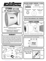
48" and 52" Hyflo
TM
Fans
Installation and Operators Instruction Manual
Fan and Fan Framing Dimensions
MV1747-016 04/ 03
Item 48" Hyflo 52" Hyflo
1 41-7/8" [106.36 cm] 44" [111.76 cm]
2 59" [149.9 cm] 64" [162.56 cm]
3 5-1/8" [13.02 cm] 5-1/8" [13.02 cm]
4 12.35" [31.37 cm] 12.35" [31.37 cm]
5 2-5/16" [5.87 cm] 4-1/8" [10.48 cm]
3
2
Figure 1. Fan Dimensions
4
1
5
MV1747-017 04/03
3
2
3
2
Planning the layout of the spacing between Fans is very important.
Spacing too close together will cause interference between the
discharge Cones.
The Rough Opening dimensions for Fans are
shown above.
Item 48" Hyflo 52" Hyflo
1 4" [10.16 cm] Minimum 8" [20.32 cm] Minimum
2 55" [139.7 cm] 56-1/2" [143.51 cm]
3
1
MV1747D
July 2003
Do Not operate these Fans with a variable speed control device. Operating static pressure should be less
than 0.15 inches water column.

Fan Assembly/Installation 48" and 52" HyfloTM Fans Installation and Operators Instruction Manual
2
MV1747D
Remove the Fan from the Crate and Install into Wall opening. The Danger Decals should be located at the
bottom of the Fan as shown below. In the holes at the side center locations Use 1 Lag Screw, 2 Nylon
Washers, and 1 Screen Clip to attach the Fan to the wall (See Figure 2). These Screen Clips will later be
used to hold the Screen on. Install Lag Screws in the remaining 6 locations as shown in Figure 2.
Motor Installation
Rotate the Motor Support Bracket into the upright position by removing the Upper Carriage Bolt and Nut
and loosening the Lower Bolt and Nut (See Figure 3). Rotate the Motor Support Bracket until it is
perpendicular to the Fan Posts and fasten with (4) 5/16 Carriage Bolts and (4) 5/16 Flange Nuts. Note that
the Nuts go outside the Posts. Remove the Motor from the Crate and attach it to the Motor Support Bracket
with (4) 5/16 Carriage Bolts and (4) 5/16 Flange Nuts as shown.
Belt Installation
Guide the Belt through the Opening in the Motor Support Bracket and loop it over the Motor Sheave. Guide
the Belt around the Tensioner Sheave and push on it to get enough slack to put the Belt on the Driven Sheave
as shown in Figure 4. Make sure the Belt does not rub against the Motor Support Bracket.
Fan Assembly/Installation
1747-005 03/ 04
Decals at Bottom
Lag Screw Locations
Item Description
1 1/4 x 1-1/2" Lag Screw
2 Nylon Washer
3 Screen Clip
Figure 2. Installing Fan in Wall Opening
3
2
3
3
3
1
Figure 3. Attaching the Motor Support Bracket and Motor
Item Description
1 Motor Support Bracket
2 5/16 Carriage Bolt
3 5/16 Flange Nut
Lower Nut and Bolt
Hidded by Fan Post
32
3
1
333
3 2
33
3
2
3
2
Upper
3
Item Description
1 Belt
2 Motor Sheave
3 Tensioner Sheave
4 Driven Sheave
1
32
3
4
Figure 4. Installing the Belt

48" and 52" HyfloTM Fans Installation and Operators Instruction Manual Cone Assembly
MV1747D
3
The Cone Panels can be identified by the number of notches at the edge of each Panel. Begin the Cone
assembly by laying the Panel with no tabs on a couple of boards with the one notch end to the left and with
the Knock-out at the Bottom as shown in Figure 6. Insert the tabs into the slots on the edge with the same
number of notches.
When all four Cone Panels are connected stand the panels up on edge and curl the Cone around with the
smaller diameter of the Cone up as shown below. Assemble the final Panels together and allow the Cone to
take its shape. If the Cone is assembled correctly the Tabs should all be on the Inside of the finished Cone.
Fasten the Cone Panels together with (4) 5/16 x 1/2" Hex Bolts Threaded in from the inside of the finished
Cone as shown in Figure 7.
Cone Assembly
3
3
3
3
4
Item Description
1 Tab
2 Panel with No Tabs
3 1 Notch Panels
4 No Notch Panels
5 Knock-out
Figure 6. Assembling Cone Panels
3
1
2
3
5
Holes Nearest Cone Panels Edge
3
2
3
1
Item Description
1 5/16 x 1/2" Bolt
2 5/16 Flange Nut
Figure 7. Bolting Cone Panels

Door Assembly/Installation 48" and 52" HyfloTM Fans Installation and Operators Instruction Manual
4
MV1747D
To install the Door in the Cone you must first identify the top of the Cone and the top of the Door. The
bottom of the Cone Has a C-shaped cut-out in it that will later be used for a drainage knockout (See Figure
8). The top of the Door can be identified by the location of the Door Springs. The Spring attaches to the Post
towards the top of the Door (See Figure 8). With the Door opening towards the ground, as shown below,
line up the Four Holes in the Door Ring with the second set of holes from the edge of the Cone and thread
(4) 5/16 x 1.25" Bolts in until they are tight. Do not install Nuts at this time. These Bolts will be used later
to attach the Cone Brackets.
Use (2) 5/16 x 1.25" Bolts and 5/16 Flange Nuts to attach the Ring to the Cone using the Holes located on
both sides near the Door Center Brace as shown below. Note that the Nuts go on the outside of the Cone.
Turn the Cone over to install the Grill. Orient the Grill so the Leg with the bent spokes at the Center of the
Grill is Parallel with the Center Door Hinge and that the bent Spokes are either above or below center. Not
to the left or right. (See Figure 10). Install the Rubber Grommet 3/4" to 1" from the end of the bent Spokes.
Fasten the Grill on with (8) 5/16 x 1/2" Carriage Bolts and Flange Nuts as shown below. Note that the Nuts
are to the Inside of the Cone.
Door Assembly/Installation
Top of Cone
C-shaped Knockout
Spring attaches toward
the Top of Post
Post
Top of Door
Second Set of Holes
Figure 8. Installing the Door
from Edge of Cone
Item Description
1 5/16 x 1/2" Carriage Bolt
2 5/16 Flange Nut
3 Door Center Brace
3
1
3
2
Figure 9. Attaching the Ring to the Cone
3
3
3/4" to 1"
32
3
3
Item Description
1 5/16 x 1/2"
Carriage Bolt
2 5/16 Flange Nut
3 Rubber Grommet
4 Leg with Bent
Spokes
31
Figure 10. Attaching the Grill
3
4
Parallel

48" and 52" HyfloTM Fans Installation and Operators Instruction Manual Assembling the Cone to the Fan
MV1747D
5
Use 5/16 x 1/2" Carriage Bolts and 5/16 Flange Nuts to attach the Cone Brackets to the Fan Shroud as
shown. The Shorter Cone Brackets go on the top. The Longer Cone Brackets go on the bottom as shown in
Figure 11.
Mounting the Cone and Door Assembly on the Fan requires at least two people. Pick up the Cone and rest
the Cone on top of the Fan Orifice as shown in Figure 12A. Attach the top of the Cone to the Cone Brackets
with the Bolts that were previously threaded through the Ring and Cone and 5/16 Flange Nuts (Figure 12A).
Only hand tighten the Nuts at this time. Working around the Fan Orifice in a circular motion Slide the Cone
over the Fan Orifice. The Cone will Fit snug over the Fan Orifice. Use the Bolts previously threaded through
the Ring and Cone and the 5/16 Flange Nuts to secure the bottom of the Cone to the Fan (Figure 12B). Use
a Level and rotate the Cone until the Door center rail is Vertical. Now tighten all Hardware (See Figure
12C).
Assembling the Cone to the Fan
Figure 11. Attaching the Cone Brackets
Item Description
1 Long Cone Bracket
2 Short Cone Bracket
3 5/16 x 1/2" Carriage Bolt
4 5/16 Flange Nut
3
2
31
3
3
3
4
3
2
3
1
Cone resting on Fan Orifice
3
3
3
2
Figure 12B. Attaching the Cone
Item Description
1 Short Cone Bracket
2 5/16 Flange Nut
3 Long Cone Bracket
Door Center Rail Vertical
Figure 12A. Attaching the Cone
Figure 12C. Attaching the Cone

Wiring 48" and 52" HyfloTM Fans Installation and Operators Instruction Manual
6
MV1747D
1.Check that the electrical power being supplied to the Fan matches the electrical Specifications on the Fan
Decal.
2. Remove the Motor Access Cover.
3. Install an electrical disconnect within reach of each Fan installed.
4. Connect the cord to the motor according to the wiring diagram on the motor. Verify that the motor is
connected for counter clockwise rotation (viewing the back of the motor, opposite the shaft end.)
Follow local, state, and national electrical codes for wiring.
Cut out one section of the Screen to route the cord out of the Fan: This will allow for the Screen to be
removed without interfering with the Cord.(See Figure 13). Attach the cord to the Wall using a Lag Screw
and Cord Clip. Allow enough slack in the cord to form a "drip loop" for moisture to fall away from the cord
and not into the motor.
Hang the Rear Screen on the four tabs located in the corners of the Fan Mounting Flange. Position the Screen
so that the Screen wire is captured between the 1/8" tall tabs and the Screen Clips. Rotate the two Screen
Clips to capture the Screen (See Figure 14).
Wiring
Installing the Screen
Item Description
1 Motor Access Cover
2 Cord Clip
3 Drip Loop
3
1
3
2
3
3
Figure 13. Cut out Screen for Motor Wiring
3
2
31
3
3
3
3
Item Description
1 Screen Clip
2 1/8" tall Tab
3 Screen Mounting
Tabs
Figure 14. Installing the Screen

48" and 52" HyfloTM Fans Installation and Operators Instruction Manual Maintenance
MV1747D
7
IMPORTANT! Disconnect Power Prior To Maintaining Or Cleaning The Fan. The fan may start
automatically causing serious injury or death.
• Service and repair of fans should be done only by a qualified technician.
• Keep the fan clean for maximum life and best performance. Do Not spray water on Fan Shaft Bearings
or Motor.
• Periodically check the V-Belt and replace if necessary. A worn Belt will cause a substantial drop in Fan
performance or it can break and cause Fan failure. If a Belt rides below the Sheave edge, replace the belt.
(See Figure 15 below)
• Check Belt Tension.The Belt
should be tensioned just tight
enough to minimize Belt slippage.
Over tensioning the belt will
cause premature Belt and Bearing
wear. With a new Belt the Idler
Sheave indicator mark should line
up with the third notch in the Ten-
sioner Housing (See Figure 16).
• Keep Shutters, Blades, and Housing clear of obstacles for best air performance.
• The motor and Fan Shaft Bearings are pre-lubricated. Grease zerks are provided on the fan shaft bearings
for installations where re-lubrication is needed. Add only a small amount of grease to purge impurities
out of the bearing seals. Use only high quality lithium soap base grease and clean all dirt from zerk before
applying grease. Chore-Time recommends using Shell Alvania # 2 in the fan shaft bearings.
Check Sheaves for wear. Replace if a Sheave groove is worn. (See Figure 17)
Maintenance
Bad Belt
Good Belt
1747-054 04/03
Bad Belt (Needs Replaced)
Figure 15. Belt Condition
Third Notch
Idler Sheave Indicator Mark
Figure 16. Idler Sheave Indicator Mark
Bad Sheave
1747-053 04/03
Bad Sheave (Needs Replaced)
Good Sheave
Figure 17. Sheave Condition

48" HyfloTM Itemized Parts 48" and 52" HyfloTM Fans Installation and Operators Instruction Manual
8
MV1747D
48" Hyflo
TM
Itemized Parts
3
10
34
3
30
39
3
16
3
18
3
12
3
15
3
14
3
7
36
3
19
33
3
5
3
8
311
3
13
3
25
3
22
3
23
3
21
3
20
3
26
3
27
3
33
3
29
3
2
3
17
3
32
3
31
3
24
3
1
3
28

48" and 52" HyfloTM Fans Installation and Operators Instruction Manual Part Numbers
MV1747D
9
Part Numbers
Chore-Time Hyflo
TM
Fan Part Numbers
48" Fans
48320-XX
52" Fans
48483-XX
Item Part Description Part No. Models Part No. Models
1
Motor, 1ph, 1.5hp, 1725 rpm 47691 -21 47691 -22
Motor, 1ph, 1hp, 1725 rpm 37729 -22, -23
Motor, 3ph, 1.5hp, 1725 rpm 47693 -41, -51, -52 47693 -42, -52
Motor, 3ph, 1hp, 1725 rpm 40157 -42
Motor, 1ph, 1.5hp, 1725 rpm 48580 -21
Motor, 3ph, 1.5hp, 1725 rpm 48608 -41, -51
2 Shroud, Fan 48362 All 47710 All
3 Post, Fan 48393 All 48072 All
4 Motor Support, Idler Drive 48396 All 48396 All
5 Bearing Support, Idler Drive 48395 All 48395 All
6 Tensioner Support 48394 All 48394 All
7 Tensioner, Assy 3.5" Arm 3" Dia. 48429 All 48429 All
8 Bearing, 1" Pillow Block 48428 All 48428 All
9 Fan Shaft 48397 All 48397 All
10
Fan Blade, High Efficiency 45932 -23
Fan Blade, Standard 28140 -22, -42, -52 48507 -22, -42, -52
Fan Blade, High Capacity 46748 -21, -41, -51 48125 -21, -41, -51
11 Sheave, Driven AK84 28143 -51, -52, -23 28143 -51, -52
Sheave, Driven AK94 40274 -21, -22, -41, -42 40274 -21, -22, -41, -42,
12 Hyflo Top Panel 48671 All 48685 All
13 Hyflo R.H. Side Panel 48672-2 All 48684-2 All
14 Hyflo L.H. Side Panel 48672-1 All 48684-1 All
15 Hyflo Bottom Panel 48673 All 48686 All
16
Sheave, Driver AK27 1381 -23
Sheave, Driver AK30 8773 -21, -22, -41, 42 8773 -21, -22, -41, -42
Sheave, Driver AK32 48504 -51, -52 48504 -51, -52
17 Screen Clip 36729 All 36729 All
18 Screen Assembly 48794 All 48794 All
19 Grommet, .31 ID x .75 OD 48426 All 48426 All
20 Cone Panel, RH Hyflo 48311 All 48447 All
21 Cone Panel, Bottom Hyflo 48659 All 48683 All
22 Cone Panel, Top Hyflo 48658 All 48682 All
23 Cone Panel, LH Hyflo 48657 All 48681 All
24 Grill, Galv. Cone 47944 All 48475 All
25 Frame, Hyflo Door 48185 All 48434 All
26 Plate, Fan Door Pivot Bottom 48190 All 48190 All
27 Spring 48440 All 48440 All
28 Magnet, .125 Thk. x .50 Dia. 48427 All 48427 All
29 Bracket, Cone Top Support 48313 All 48470 All
30 Bracket, Cont Bottom Support 48312 All 48469 All
31
V-Belt A59 48505 -51, -52, -23 48505 -52
V-Belt A60 48430 -21, -22, -41, -42 48430 -22, -42
V-Belt AX59 48615 -51
V-Belt AX60 48541 -21, -41
32 Door, Hyflo Shutter 48193 All 48453 All
33 Pop Rivet, SS 1/8 x .40 48936 All 48936 All

Safety Information 48" and 52" HyfloTM Fans Installation and Operators Instruction Manual
10
MV1747D
Carefully read all safety messages in this manual and on your equipment safety signs. Follow recommended
precautions and safe operating practices. Keep safety signs in good condition. Replace missing or damaged
safety signs.
DANGER: Electrical Hazard
Disconnect electrical power before inspecting or servicing equipment Ground
all electrical equipment for safety. All electrical wiring must be done by a
qualified electrician in accordance with local and national electric codes.
Ground all non-current carrying metal parts to guard against electrical shock.
With the exception of motor overload protection, electrical disconnects and
over current protection are not supplied with the equipment.
DANGER: Rotating Fan Blade
Keep Hands away. Disconnect power before servicing. Fan may start
automatically. Do not operate the Fan without the screens in place. Disregard
to these things will cause serious injury including death.
Chore-Time Equipment (“Chore-Time”) warrants each new Chore-Time product manufactured by it to be free from
defects in material or workmanship for one year from and after the date of initial installation by or for the original
purchaser. If such a defect is found by the Manufacturer to exist within the one-year period, the Manufacturer will, at
its option, (a) repair or replace such product free of charge, F.O.B. the factory of manufacture, or (b) refund to the
original purchaser the original purchase price, in lieu of such repair or replacement. Labor costs associated with the
replacement or repair of the product are not covered by the Manufacturer.
Conditions and Limitations
1. The product must be installed by and operated in accordance with the instructions published by the Manufacturer
or Warranty will be void.
2. Warranty is void if all components of the system are not original equipment supplied by the Manufacturer.
3. This product must be purchased from and installed by an authorized distributor or certified representative thereof or
the Warranty will be void.
4. Malfunctions or failure resulting from misuse, abuse, negligence, alteration, accident, or lack of proper maintenance
shall not be considered defects under the Warranty.
5. This Warranty applies only to systems for the care of poultry and livestock. Other applications in industry or
commerce are not covered by this Warranty.
The Manufacturer shall not be liable for any Consequential or Special Damage which any purchaser may suffer or
claim to suffer as a result of any defect in the product. “Consequential” or “Special Damages” as used herein include,
but are not limited to, lost or damaged products or goods, costs of transportation, lost sales, lost orders, lost income,
increased overhead, labor and incidental costs and operational inefficiencies.
THIS WARRANTY CONSTITUTES THE MANUFACTURER’S ENTIRE AND SOLE WARRANTY AND THIS
MANUFACTURER EXPRESSLY DISCLAIMS ANY AND ALL OTHER WARRANTIES, INCLUDING, BUT
NOT LIMITED TO, EXPRESS AND IMPLIED WARRANTIES AS TO MERCHANTABILITY, FITNESS FOR
PARTICULAR PURPOSES SOLD AND DESCRIPTION OR QUALITY OF THE PRODUCT FURNISHED
HEREUNDER.
Chore-Time Distributors are not authorized to modify or extend the terms and conditions of this Warranty
in any manner or to offer or grant any other warranties for Chore-Time products in addition to those terms
expressly stated above. An officer of CTB, Inc. must authorize any exceptions to this Warranty in writing.
The Manufacturer reserves the right to change models and specifications at any time without notice or
obligation to improve previous models.
Contact your nearby Chore-Time distributor or representative for additional parts and information.
CTB Inc.
P.O. Box 2000 • Milford, Indiana 46542-2000 • U.S.A.
Phone (574) 658-4101 • Fax (877) 730-8825
E-Mail: [email protected] • Internet: http//www.ctbinc.com
Printed in the U.S.A.
Safety Information
Warranty
/