Page is loading ...

2
BOX CONTENTS
y TMX160DFX
y Power cable
y Quickstart Guide
y Safety Instructions & Warranty Information booklet
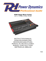
CONNECTION DIAGRAM
QUICK SETUP
Follow the procedure below to have a signal processed for each channel:
1. Set all channel levels to zero, set pan to the middle, set output to zero, and set EQ’s flat.
2. Connect your mic and then apply phantom power if your mic requires this.
3. Set the Main output level to no more than 75% and the Monitor output to no more than 50%.
4. Bring up the channel level.
5. Repeat steps 1 and 2 to setup more channels.

3
INPUTS
1. MONO INPUTS – Connect a microphone or line level instrument to these inputs using
standard XLR or ¼” cable.
2. MONO Channel INSERT - Connect external sound processors such as compressor-limiter,
equalizers, etc. The Insert sockets can be used as direct-outs to feed the input of a 4-track
tape recorder.
3. STEREO INPUTS- Stereo pair ¼” TRS connections. If you connect only to the left jack, the
input will operate in mono mode, (the mono signal will appear on both input channels).
CHANNEL CONTROLS
4. PHANTOM PWR Switch - Applies +48 Volt Phantom Power only to the XLR MIC input.
When condenser microphones are not used, make sure that the Phantom Power is
disengaged.
5. MONO IN GAIN – Adjusts the signal for mic and line level sources.
6. LEVEL LED – Activates when there is an incoming signal.
7. LOW CUT Button - Activates a 75 Hz low frequency filter to reduce hum noise or
microphone rumble.
8. STEREO IN GAIN – Adjusts gain for the stereo line level channels.
1
LINE IN
INSERT
MIC
1
1
2
LINE IN 9
LINE IN 10
3
+48V (CH1-4)
4
1
LOW CUT
75HZ
18dB/OCT
0dB
-30dB
+15dB LINE
+44dB MIC
5
7
6
8

4
EQ
9. HI EQ (TREBLE) – Adjusts the high (treble)
frequencies of the channel.
10. MID EQ – Adjusts the mid-range frequencies
of the channel.
11. LOW EQ (BASS) – Adjusts the low (bass)
frequencies of the channel.
12. AUX SENDS – Adjusts the level of the signal
sent to AUX bus. AUX1 and AUX2 can be
switched to PRE / POST-FADER via the
PRE/POST button. AUX3 and AUX4 are
configured as POST-Faders. AUX SEND 4
can also be assigned to the internal effect
module.
13. PAN/BAL- Pan and balance control to adjust
the mono or stereo image of the signal.
14. MUTE SWITCH - Pressing this switch is equal to turning the fader down, which can silence the corresponding
channel output except for the Pre Aux sends and channel Insert send.
15. PFL Switch - Sends a signal from a post-EQ, pre-fader location to the PHONES jack for monitoring.
16. PEAK LED – When the LED is red illuminated, it warns you that you are reaching signal saturation and
possible distortion. Reduce the input level to avoid distortion.
17. FADER - Adjusts the overall level of the channel and sets the amount of signal sent to the main output.
MASTER SECTION
18. 2-TRACK IN/OUT - Use the Tape input to listen to your mix from a Tape Recorder, CD player, DAT, etc. The
Tape output jacks will route the main mix into external devices.
19. AUX/DFX SENDS CONNECTORS - 1/4" phone jacks used to send out signal from the AUX bus to external
devices such as effect units or stage monitors.
20. P. AMP INPUT Jacks - 1/4" phone jacks used to input line level stereo signals to the built-in power amplifier.
21. ST OUT Jacks - Outputs the signal of the STEREO bus. The final output level from these jacks is adjusted by
the ST OUT fader.
22. ST SUB OUT Jacks - Outputs the signal of the STEREO bus. Use the ST SUB OUT control to adjust the final
output level at the ST SUB OUT jacks.
23. ST SUB IN 1-3 Jacks - Used to connect to the stereo output of a sub mixer or external effect processor. The
signal input can be routed to the AUX1-3 bus and STEREO bus.
24. MONO OUTPUT Jack - Use this balanced MONO jack to connect the input of an external amplifier or active
speaker.
25. FOOTSWITCH JACK - 1/4'' jack used to connect an external foot switch to turn on/off the onboard effect
module.
26. PHONES - Sends the signal to a pair of headphones.
27. LAMP - 12V socket that can drive standard BNC-type lamp.
28. LED METER DISPLAY - Indicates the output signal level. By pressing the switch, you can choose the output
signal source. When the switch is off, the stereo LED meter will indicate the signal level sent to ST OUT
outputs. When the switch is on, the LED meter indicates the signal level sent to PHONES output.
29. ST SUB OUT Control - Adjusts the final level of the signal sent from the ST bus to the ST SUB OUT jacks.
AUX SEND 1 P. AMP INPUT ST OUT
ST SUB IN 2 ST SUB IN 3ST SUB IN 1
ST SUB OUT MONO OUT
FOOT SWITCH
PHONES
LAMP
(12V/0.5A)
AUX SEND 2
DFX1 SEND
DFX2 SEND
19
20
21
22
23
24
25
26
27
2 TRACK IN/OUT
IN
OUT
18
ST SUB OUT
LR
-2
-4
-10
-20
-7
-30
10
CLIP
2
4
7
0
ST
AFL.PFL
28
29
FREQ
100Hz 8KHz
10
11
9
POST
PRE
POST
PRE
DFX1
(EXT)
DFX2
(EXT)
BAL
1
2
3
1
2
3
4
12
13
MUTE
14
PFL
10
dB
-5
-10
-20
-25
-30
-40
-60
0
5
15
16
17

5
30. AUX1-3 Controls - Adjusts the amount of the signal sent from the
ST SUB IN1-3 jacks to the AUX 1, 2 and 3 buses.
31. ST (stereo) Controls - Adjusts the amount of stereo signal sent
from the ST SUB IN1-3 jacks to the STEREO bus.
32. PFL (pre-fader listen) Switch - When this switch is engaged, the
signal at the point before the ST control knob is sent to the
PHONES jack.
33. POWER LED - The LED indicates when the power is switched
on.
34. PHONES Control - Controls the signal sent to the Headphone
Output.
35. LPF (MONO OUT) - This switch applies a low-pass filter to the
signal that is output from the STEREO bus. You can adjust the
frequency to the desired position by using a screwdriver to turn
the LPF Control.
36. ST (stereo) Control - Adjusts the level of the signal sent from the
2TR IN jacks to the STEREO bus.
37. PFL (Pre-fader listen) Switch - When this switch is engaged, the
signal input from the 2TR IN jacks is routed at the point before the
ST control to the PHONES jack.
38. AFL Switch - When this switch is on, the output
signal that passes through the ST OUT control fader
is sent to the PHONES jack.
39. PFL Switch - When this switch is engaged, the signal
at the point before the ST OUT control fader is sent to
the PHONE jack.
40. DFX RTN Fader - Adjusts the level of the return
signal which is sent from the built-in DSP to the
STEREO bus.
41. AUX1-3 Fader - The AUX1-3 faders adjust the final
level of the signal sent from the AUX1-3 bus to the
AUX SEND1-3 jacks.
42. MONO OUT Fader - Adjusts the final level of the
signal output from the STEREO bus to the MONO
OUT jack.
43. ST OUT Fader - The ST OUT fader adjusts the final
level of the signal sent from the STEREO bus to the
ST OUT jacks.
GRAPHIC EQ
44. EQ SWITCH - Engage this button to add the stereo graphic
EQ into the main mix output.
45. STEREO GRAPHIC EQ - Boosts or attenuates (+/-15dB) the
selected frequency at a preset bandwidth.
POWER AMP
46. POWER AMP. MODE Switch - Provides three modes: MAIN L / MAIN R;
AUX1/MONO; BRIDGE. Select any one of these modes to specify the signals to be
routed to the corresponding jacks according to the speaker connection on the rear
panel.
47. POWER AMP Switch - This switch is used to control the amplifier input signal.
DFX RTN AUX 1 AUX 2 AUX 3 MONO
OUT
STEREO
OUT
PFL
10
dB
-5
-10
-20
-25
-30
-40
-60
0
5
10
dB
-5
-10
-20
-25
-30
-40
-60
--
0
5
AFL AFL AFL AFL AFL
10
dB
-5
-10
-20
-25
-30
-40
-60
-
0
5
10
dB
-5
-10
-20
-25
-30
-40
-60
-
0
5
10
dB
-5
-10
-20
-25
-30
-40
-60
-
0
5
10
dB
-5
-10
-20
-25
-30
-40
-60
-
0
5
PFL
PFL
PFL
PFL
PFL
38
ST SUB IN 1
ST SUB IN 2
ST SUB IN 3
2TR IN
40
41
42
43
39
EQ OFF
EQ ON
-15
0
-10
-5
+10
+5
63
500250125
2K
1K
-15
0
-10
-5
+15
+10
+5
16K
8K4K
+15
44
45
AB
POWER AMP
OFF
ON
BRIDGE
AMP MODE
MAIN R
MONO
MAIN L
AUX 1
46
47
ST
PFL
AFL
1
2
3
ST SUB IN 1
30
31
32
ST
OFF ON
PFL
MONO OUT
PHONES
POWER
LPF(MONO OUT)
33
34
35
36
37

6
INTERNAL EFFECTS
48. PRESETS Control - Adjust this knob to select the internal effect you want to use.
49. VARIATIONS Control - 16 variations for each preset to further adjust the internal effects.
50. DFX MUTE Switch & PEAK LED - Activates/deactivates the internal effects. This LED lights
up when the input signal is too strong. When the effect module is muted, this LED also lights
up.
REAR PANEL
51. POWER ON/OFF Switch - Turns
the main power ON and OFF.
52. AC Inlet with FUSE Holder -
Connect the mixer to an AC power
outlet with the supplied AC cord.
Please check the voltage available
in your country and how the
voltage for your mixer is configured before attempting to connect the
mixer to the main AC.
53. VENTS - These vents are used for ventilation and heat dissipation.
54. SPEAKERS Jacks These jacks are used to connect speakers.
Note: In order to avoid damage to the built-in amplifier, pay attention to the
allowed impedance of the speaker. Very low load impedances may damage
the amplifier.
1. VOCAL 1
2. VOCAL 2
3. LARGE HALL
4. SMALL HALL
5. LARGE ROOM
6. SMALL ROOM
7. PLATE
8. TAPE REVERB
9. SPRING REVERB
10. MONO DELAY
11. STEREO DELAY
12. FLANGER
13. CHORUS
14. REVERB+DELAY
15. REVERB+FLANGER
16. REVERB+CHORUS
48
49
50
52
51
53
54

7
INSTALLATION AND CONNECTION
MAIN L + MAIN R Mode
The built-in amplifier drives two main speaker cabinets Left and Right. The AMPLIFIER
MODE is on MAIN L+MAIN R position.
AUX1 + MONO Mode
With the AMPLIFIER MODE in AUX1+MONO position, Output 1 drives a Main speaker
cabinet while Output 2 drives a stage monitor.
Main Speaker
Main Speaker
Use either the Speakon jacks
or 1/4" jacks
Main Speaker
Stage Monitor
Use either the Speakon jacks or
1/4" jacks

8
Bridge Mode
With the AMPLIFIER MODE switch in BRIDGE position the two power amplifiers drive
together a single speaker cabinet with the sum of the power of the 2 amps. This is
commonly used to drive a single subwoofer and the main output on the front panel is used
to feed a pair of powered speakers.
EFFECTS LIST
# PRESET DESCRIPTION PARAMETER RANGE
1 VOCAL 1 Reverb, simulating a room with a small delay time.
Decay time
Pre-delay
0.8~1.1s
0~79ms
2 VOCAL 2
Reverb, simulating a small space with a small delay
time.
Decay time
Pre-delay
0.8~2.5s
0~79ms
3 LARGE HALL Reverb, simulating a large acoustic space.
Decay time
Pre-delay
3.6~5.4s
23~55ms
4 SMALL HALL Reverb, simulating the acoustics of a stage space.
Decay time
Pre-delay
1.0~2.9s
20~45ms
5 LARGE ROOM Reverb, simulating a studio with many early reflections.
Decay time
Pre-delay
2.9~4.5s
23~55ms
6 SMALL ROOM Reverb, simulating a bright studio room.
Decay time
Pre-delay
0.7~2.1s
20~45ms
7 PLATE Simulates bright plate reverb.
Decay time
Pre-delay
0.6~6.1s
10ms
8 TAPE REVERB
Simulates classic tape delay created by multiple
playback heads.
Decay time
Pre-delay
1.3~5.4
0~84ms
9 SPRING REVERB
Simulates the lightly stretched sound of spring reverb
from analog transducers.
Decay time
Pre-delay
1.3~5.4s
0~84ms
10 MONO DELAY Reproduces the signal after a small period of time. Delay period 60~650ms
11 STEREO DELAY
Reproduces the signal after a small period of time with a
slight difference between the two stereo channels.
Delay period
Feedback
210~400ms
37~73%
12 FLANGER
Classic stereo flanging effect, similar to a jet plane
taking off.
Rate 0.16~2.79Hz
13 CHORUS
Simulates the full, complex, watery sound of several
instruments playing the same thing.
Rate 0.5~5Hz
14 REVERB+DELAY Delay effect with room reverb.
Delay period
Reverse decay time
211~375ms
1.0~2.9s
15 REVERB+FLANGER Stereo flanger effect with room reverb.
Flanger rate
Reverse decay time
0.16~2.52Hz
16 REVERB+CHORUS Stereo chorus effect with room reverb.
Chorus rate
Reverse decay time
0.5~4.74Hz
1.5~2.9s
Main Speaker

9
TROUBLESHOOTING
SYMPTOM
CAUSE
ACTION
No sound from speaker.
Signal source (mixer, instrument,
etc) is not sending.
*Check VU meters on the
source mixer;
*Verify that the tape or CD is
playing;
*Use headphones to verify
that the instrument is actually
sending an audio signal
Signal sounds distorted
and very loud; LIMIT
light is lit most of the
time.
Excessive input signal; trying to
exceed the capabilities of the
speakers.
*Reduce the output level of
the source;
*Turn down the level controls
on the speaker;
*Try another pair of speakers
Lots of hiss in the sound,
the mixer controls are
at very low settings.
Improper gain structure.
*Make sure that the MIC/LINE
switch is in the LINE
(disengaged) position;
*Reduce the level settings at
speaker, review the Owner's
Manual for your mixer and
adjust controls as needed;
*Input sensitivity(gain);
*Channel faders;
*Master faders;
Noise or hiss heard at
Output.
Noisy source device.
Disconnect the devices that
are connected to your speaker
one at a time. If the noise
goes away, the problem is
with the source or the
connecting cable.
Hum or Buzz increases or
decreases when the mixer
level controls are moved.
Improper A/C ground or faulty
equipment connected to mixer
input. Faulty cable between
source equipment and mixer.
Disconnect or mute channels
on at a time to isolate the
problem.
Substitute a known good
cable for the suspected faulty
cable.

50
TECHNICAL SPECIFICATIONS
INPUT CHANNELS
• Microphone Input: electronically balanced, discrete input configuration
• Frequency response: 10 Hz to 55 kHz, +/ -3 dB
• Distortion (THD + N) 0.005% at +4 dBu, 1 kHz
• Signal to Noise Ratio: 115dB
• Line input Electronically Balanced
• Frequency response 10 Hz to 55 kHz, +/ -3 dB
IMPEDANCES
• Microphone input: 1.4 kOhm
• Channel Insert Returns: 2.5 kOhm
• All other inputs 10 kOhm or greater
• Tape out 1 kOhm
• All other outputs 120 Ohm
POWER SECTION
• Main voltage 100 VAC ~ 60 Hz 230 VAC ~ 50 Hz; 120 VAC ~ 60 Hz 240 VAC ~ 50 Hz
• Inrush current at initial switch-on: 12.09 A
• Inrush current after power supply interruption: 13.81 A
POWER CONSUMPTION
• Stereo mode: 2 x 750 W @ 4 Ohm (EIAJ), 2 x 520 W @ 4 Ohm (RMS)
• Bridge mode: 1500 W @ 8 Ohm (EIAJ)
DIMENSIONS (H x W x D)
• 565mm x 555mm x 145 mm (22.2” x21.8” x 5.7”)
NET WEIGHT
• 12.5 kg (27.6 lb)

www.altoprofessional.com
MANUAL VERSION 1.1
/