Supermicro X6DA8-G Addendum Manual

Category
Motherboards
Type
Addendum Manual

This manual is also suitable for

Page 1 of 2
Addendum to MNL#724-- for the X6DA8-G/X6DAE-G & X6DA8-G2/X6DAE-G2 motherboards
Attention!!
Important Notice!!
(Read the information listed below before using this product.)
1. For the X6DA8-G/X6DAE-G boards:
Jumpers XJ4F1/XJ4F2 (PLLSEL Select): These jumpers allow the user to select PLLSEL (Memory Speed). Make
sure that the jumper settings are set correctly according to your memory speed before you power on the system.
(*Warning!! If these jumpers are not set correctly according to your memory speed, video display failure may
occur!!!)
DDR
*333 MHz
266MHz
XJ4F1 XJ4F2
Closed Closed
Open Open
PLLSEL Select
Jumper Settings
(XJ4F1/XJ4F2)
(*Default:Closed-333MHz)
KB/
Mouse
DIMM 4A
DIMM 4B
DIMM 3A
DIMM 3B
DIMM 2A
DIMM 2B
DIMM 1A
DIMM 1B
SPKR
GLAN
Enable
Tumwater
(NorthBridge)
(South
Bridge)
IPMI 2.0
BIOS
7902
SCSI
CTRL
IDE #1
IDE #2
Floppy
Fan4
FPUSB 6/7
JD2
SATA0
JPA3
F
P
C
T
R
L
J
F
1
FAN7
PW SMB
CPU1
CPU2
J9
J40
J3
J4
JP8
JD
1
J24
X
J
4
F
2
USB 0/
1/2/3
JL
A
N
1
CO
M
2
CO
M
1
Parrallel
Port
Fan6
Fan5
J32
4-pin
PWR
Bank 1
Bank 1
Bank 2
Bank 2
Bank 3
Bank 3
Bank 4
Bank 4
ATX PWR
J1B4
JPF
Force
PW
(**JL
A
N
)
Line_In/
Line_Out
X
J4
F
1
(PLL
Select*)
JP
C
1
Audio
Enable
SI/O
x16 PCI EXP #6
PCI #5-33MHz
PCIX#3-133M
Hz
PCIX#2-100M
Hz
J
2
7
B
IO
S
D
ebug
C
D
1
C
D
2
PCIX#1-100MHz ZCR
GLAN
CTRL
JPL1
Battery
JWOR
SMBus
J
2
2
SATA1
SCSI Ch B
JPA2
SCSI Ch A
JA1
JA2
F
a
n
3
Cha.
Intru
JPA1
SCSI CTRL
Enable
J
2
0
J
W
D
WD
JK
1
Keylock
Fan8
PWR
Fault
(*X6DA8/
E
-
G)
JBT1
Clear
cmos
FAN1
3rd PS
Alarm
OH
LED
PWR
LED
SPKR
ICH
SPKR
J1D1
12V 8-
pinPW
SCSI Ch.A
Term.
SCSICh.B
Term.
JC
2
Mic
JC
1
x4 PCI EXP #4
JWOL
JL1
JP13
JP14
JOH1
JP15
PW
Fault
(*X6DA8/
E-G2)
JP12
PXH
LAN
USB4/5
JD
3
FAN2
WOL
WOR
JP12
PW
Fail
2. For the X6DA8-G/X6DAE-G & the X6DA8-G2/X6DAE-G2 models:
J1D1 (12V 8-pin PWR) and J32 (12 V 4-pin PWR): Make sure that both PWR Connectors are used to ensure
adequate power supply to the system and the CPU.
XJ4F1/XJ4F2
(PLLSEL Select):
(*X6DA8-G/
X6DAE-G Only)
J1D1 (12V 8-pin
PWR)
(*Note: the default setting is “Closed” for both jumpers to
enable DDR Memory at 333MHz. However, if your memory
speed is 266MHz, please make sure to set both jumpers
to “Open”.)
J32 (12V 4-pin
PWR)
Add-X6DA8-G-MNL#724-6/11/04
Page 2 of 2
Addendum to MNL#724-- for the X6DA8-G/X6DAE-G & X6DA8-G2/X6DAE-G2 motherboards
Add-X6DA8-G-MNL#724-6/11/04
(Caution! We do not recommend that the
CPU or the heatsink be removed. However,
if you do need to un-install the heatsink,
please follow the instructions below to
uninstall the heatsink to prevent damage
done to the CPU or the CPU socket. )
To Un-install the Heatsink
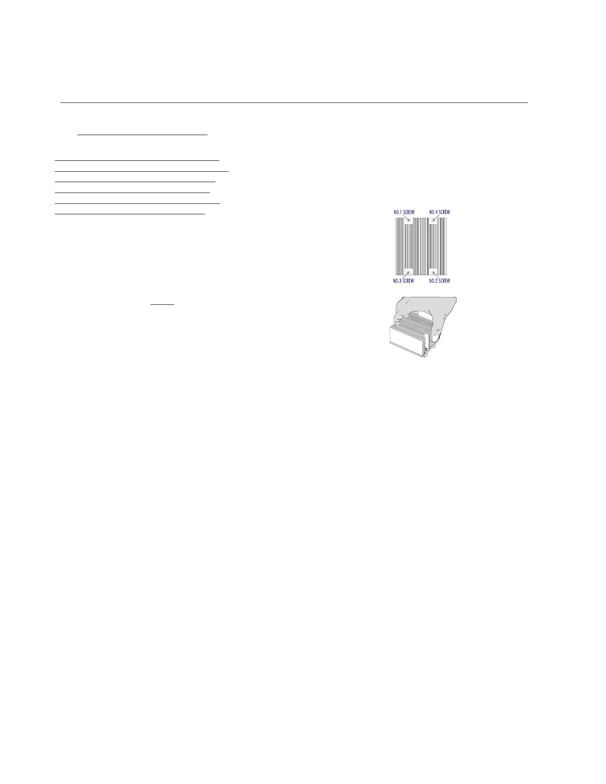
1. Unscrew and remove the heatsink
screws from the motherboard in the
sequence as show in the picture on the
right.
2. Hold the heatsink as show in the
picture on the right and gently wriggle the
heatsink to loosen it from the CPU. (Do
not use excessive force when wriggling
the heatsink!!)
3. Once the CPU is loosened from the
heatsink, remove the heatsink from the
CPU socket.
4. Clean the surface of the CPU and the
heatsink to get rid of the old thermal
grease. Reapply the proper amount of
thermal grease on the surface before
you re-install the CPU and the heatsink.
  • Page 1 1
  • Page 2 2

Supermicro X6DA8-G Addendum Manual

Category
Motherboards
Type
Addendum Manual
This manual is also suitable for

Ask a question and I''ll find the answer in the document

Finding information in a document is now easier with AI