Page is loading ...

12
Manufacture’s Limited Warranty Pull Behind Accessories
The limited warranty set forth below is given by Precision
Products Inc. with respect to new merchandise
purchased and used in the United States, its possessions
and territories.
Precision Products Inc. warranties the product(s) listed
against defects in material and workmanship, and will at
our option, repair or replace, free of charge, any part
found to be defective in m aterials or
workmanship. This limited warranty shall only apply if
this product has been assembled, operated, and
maintained in accordance with the owner’s manual
furnished with the product, and has not been subjected
to misuse, abuse, neglect, accident, improper
maintenance, alteration, vandalism, theft, fire, water, or
damage because of other peril or natural disaster.
Normal wear parts or components thereof are subject to
separate terms as follows: All normal wear parts or
component failures will be covered on the product for a
period of one year. Parts found to be defective within the
warranty period will be replaced at our expense. Our
obligation under this warranty is expressly limited to the
replacement or repair, at our option, of parts found to be
defective in material and workmanship.
Contacting Service
Warranty parts replacements are available, ONLY WITH
PROOF OF PURCHASE, through our Customer Service
Department.
Call 1 (800) 225-5891
This limited warranty does not provide coverage in the
following cases:
1. Routine maintenance items such as lubricants and
filters.
2. Normal deterioration of the exterior finish due to use
or exposure.
3. Transportation and/or labor charges.
No implied warranty, including any implied warranty of
merchantability of fitness for a particular purpose, applies
after the applicable period of expressed written warranty
above as to the part as identified below. No other
expressed warranty, whether written or oral, except as
mentioned above, given by any person or entity,
including a dealer or retailer, with respect to any product,
shall bind Precision Products Inc. during the period of the
warranty, the exclusive remedy is repair or replacement
of
the product as set forth above. The provisions as set
forth in this warranty provide the sole and exclusive
remedy arising from the purchase
Precision Products Inc. will not be liable for incidental or
consequential loss or damage including, without
limitation, expenses incurred for substitute or
replacement lawn care services, or for rental expenses to
temporarily replace a warranted product.
Some states do not allow the exclusion or limitation of
incidental or consequential damages, or limitations on
how long an implied warranty lasts, so the above
exclusions or limitations may not apply to you.
During the warranty period, the exclusive remedy is
replacement of the part. In no event shall recovery of
any kind be greater that the amount of the purchase
price of the product sold. Alteration of safety features of
the product shall void this warranty. You assume the risk
and liability for loss, damage, or injury to you and your
property and/or to others and their property arising out
of the misuse or inability to use this product.
This limited warranty shall not extend to anyone other
than the original purchaser or to the person for whom it
was purchased as a gift.
Local Law to this Warranty
This limited warranty gives you specific legal rights, and
you may also have other rights which vary from state to
state.
Warranty Period
The warranty period stated below begins with the Proof
of Purchase. Without the proof of purchase, the
warranty period begins from the date of manufacture.
Product Warranty Period
The warranty period for this product is as follows: All
parts are covered for 1 year.
Owner’s Manual | TT500 | 40” Tow Behind Dethatcher
Caution: Carefully read all Rules and Instructions for Safe Operation.
Manual Contents
Your New Dethatcher
Congratulations on your purchase of a new
Precision Products Inc. dethatcher. Your dethatcher
has been engineered and built to give you the most
dependable and best performing product possible.
If you experience any problem you can not easily
resolve, please feel free to contact our
knowledgeable and helpful customer service
department toll-free at 1 (800) 225-5891.
Form No. 5570 (Rev. 10/11)
Safety Instructions
Assembly
Operation
Maintenance
Parts
Warranty
2
4-9
10
10
2-3
12

2
Rules for Safe Operation
All power equipment can cause injury or property damage if operated improperly. Please read and observe
the following safety rules and exercise caution at all times when operating equipment.
Read and understand your tractor owner’s manual and towing safety rules.
Never allow children to operate the towing vehicle. Do not allow adults to operate the tractor without having read the owner’s
manual or receiving proper instruction.
Do not allow anyone to ride or sit on tow behind equipment during operation.
Keep people and animals at a safe distance.
Always wear substantial footwear. Do not wear loose fitting clothing that may get caught in moving parts.
This unit may have sharp points. Handle with care.
Keep your eyes and mind on your vehicle/attachment and area being covered. Do not let yourself be distracted.
Stay alert for holes in the terrain and other hidden hazards.
Tractor braking and stability may be affected with the attachment of this unit. Be aware of changing conditions on slopes. Refer
to safety rules in your tractor owner’s manual concerning safe operation on slopes. Stay Off Steep Slopes.
Always operate up and down a slope, never across the face of a slope.
This equipment should be operated at a reduced speed on rough terrain, along creeks, ditches and on hillsides, to prevent
tipping and loss of control.
Always begin with the transmission in first (low) gear and engine at low speed, gradually increasing speed as conditions permit.
Keep the tractor and attachment in good operating condition and keep safety devices in place.
Keep all nuts, bolts and screws tight to be sure the equipment is in safe working condition.
The tractor and attachment should be stopped and inspected for damage after striking a foreign object. Any damage should be
repaired before restarting and operating the equipment.
Follow the maintenance instructions as outlined in this owner’s manual.
Do not exceed 3-4 miles per hour.
Carton Contents
10
9
7 6
5
4 3
2 1
8
12
11
11
Ref. Qty. Part# Description
1 1 5592GY Base Plate
2 1 5561GY Tow Bar
3 1 1243GY Clevis Plate
4 1 5576GY Handle
5 1 5593GY Axle Assembly
6 2 5568GY Wheel Bracket
7 1 4263G Lever Link
8 1 4240G Link Bar
9 9 4005GY Tine
10 1 5564GY Handle Brace
11 2 3150CR Wheels
12 1 3042 Handle Grip
13 2 4271 1/2” x 3” Hex Head Bolt
14 1 5583 1/2” x 1-1/2” Hex Head Bolt
15 1 1752 5/16” x 2-1/4” Hex Head Bolt
16 1 2051 5/16” x 1-3/4” Hex Head Bolt
17 2 4014 5/16” x 1-1/2” Hex Head Bolt
18 11 3738 5/16” x 1” Hex Head Bolt
Ref. Qty. Part# Description
19 5 1248 5/16” x 3/4” Hex Head Bolt
20 1 4011 1/2” x 1-3/4” Shoulder Bolt
21 1 1840 1/2” x 1-3/4” Clevis Pin
22 1 4272 Compression Spring
23 6 1506 1/2” Flat Washer
24 2 5589 1/2” Nylon Washer
25 1 1278 3/8” Flat Washer
26 9 2172 5/16” Fender Washer
27 14 1044 5/16” Flat Washer
28 2 4295 1/2” x 1” Spacer
29 14 1276 5/16” Lock Washer
30 1 1042 #14 Hitch Pin Clip
31 2 4324 1/2” Jam Nut
32 4 4327 1/2” Nylock Nut
33 6 1749 5/16” Nylock Nut
34 14 1275 5/16” Hex Head Nut
35 1 5590 3/8” Nylock Jam Nut (thin)
36 1 5591 5/16” Nylock Jam Nut (thin)
19
22
21
10
3
16
11
18
12
4
33
17
36
35
15
23
14
31
34
9
23
8
24
33
27
5
20
34
30
29
26
27
29
13
23
32
31
6
1
25
28
2
7
33

10
Parts and Support
Please do not return this product to the
store prior to contacting Precision.
At Precision Products Inc. our goal is to
deliver quality, value and outstanding
service. If for any reason our product does not meet
your expectations please contact us and we will
take care of any problem you may have with this
unit.
When ordering replacement parts please have the
model number, part description and part number,
inspector number and date on box available so that
we can best serve you.
1 (800) 225-5891
www.precisionprodinc.com
Precision Products Inc.
STOP
Operation
Raising/Lowering the Dethatcher
1. To raise the dethatcher for transport lift up the
back until the tines are no longer in contact with
the ground.
2. To lower the dethatcher for operation, move the
Handle to the down position.
3. Do not use more than 75 lbs ballast on the Base.
Using the Dethatcher
Regular removal of thatch is a critical step for the
maintenance of a healthy lawn. Thatch is a layer of
stems, clippings, runners, roots, and leaves that has
not decayed. Excessive thatch prevents air, water,
and fertilizer from reaching the roots. The
dethatcher will effectively dislodge excessive thatch
from your lawn. Use your dethatcher in the mid-to-
late Spring and/or in early Fall.
1. Your grass should be less than 3” tall for proper
tine action.
2. Start with the tractor in low gear. Vary the
forward speed to determine the best speed for
maximum performance.
3. When in use, all tines on the dethatcher should
bend to the back and “flip” the thatch forward
as it is pulled.
4. Use a crisscross pattern to achieve the most
even removal of thatch.
5. On slopes, always operate in an up and down
direction only.
6. Avoid extremely sharp turns.
7. Not for use with Zero Turn Radius Mowers.
Maintenance
1. Before each use check all nuts and bolts for
tightness.
2. Clean after each use to prevent rust. The key to
years of trouble-free service is to keep your
dethatcher clean and dry.
3. If rust should develop, sand lightly and then
paint area with enamel.
4. Periodically check all moving parts for free
movement and if necessary, lubricate with oil.
Storage
1. Be careful to store your dethatcher with the
tines pointed towards the floor or a wall. Tines
are sharp and can cause considerable damage.
2. Always store in a dry area, and coat exposed
metal with light oil when not in use.
17
20
6
1
28
3
Hardware Package Contents
34
27 26
22
28 25
15
16
17
19 18
20
21
23 24
13
14
31
33
32
30
Ref. Qty. Description
1 1 Base Plate
2 1 Tow Bar
3 1 Clevis Plate
4 1 Handle
5 1 Axle Assembly
6 2 Wheel Bracket
7 1 Lever Link
8 1 Link Bar
9 9 Tine
10 1 Handle Brace
11 2 Wheels
12 1 Handle Grip
13 2 1/2” x 3” Hex Head Bolt
14 1 1/2” x 1-1/2” Hex Head Bolt
15 1 5/16” x 2-1/4” Hex Head Bolt
16 1 5/16” x 1-3/4” Hex Head Bolt
17 2 5/16” x 1-1/2” Hex Head Bolt
18 11 5/16” x 1” Hex Head Bolt
19 5 5/16” x 3/4” Hex Head Bolt
Ref. Qty. Description
20 1 1/2” x 1-3/4” Shoulder Bolt
21 1 1/2” x 1-3/4” Clevis Pin
22 1 Compression Spring
23 6 1/2” Flat Washer
24 2 1/2” Nylon Washer
25 1 3/8” Flat Washer
26 9 5/16” Fender Washer
27 14 5/16” Flat Washer
28 2 1/2” x 1” Spacer
29 14 5/16” Lock Washer
30 1 #14 Hitch Pin Clip
31 2 1/2” Nylock Jam Nut
32 4 1/2” Nylock Nut
33 6 5/16” Nylock Nut
34 14 5/16” Hex Head Nut
35 1 3/8” Nylock Jam Nut (thin)
36 1 5/16” Nylock Jam Nut (thin)
29
35
36

4
(2) 1/2” Wrenches
(2) 3/4” Wrenches
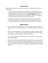
Assembly Instructions
(2) 9/16” Wrenches
(1) 1/4” Allen Wrench
Remove from Carton
Remove and layout all parts and hardware packages from the carton. Identify them using the illustrations on
pages 2 and 3.
1. Place the Base Plate on a flat surface with the front facing away for you (the front will have three bolt
holes in the center). Insert the short side of the Axle into the Axle Hole to your left. Slide the Tow Bar onto
the Axle. Slide the Axle into the Axle Hole on the right side of the Base Plate. See Figure 1.
Figure 1
Tow Bar
Front
Base Plate
Axle
9
8. Attach the Handle Grip to the Handle. Insert the 5/16” x 1-3/4” Hex Head Bolt in to the top hole
in the Handle (from the right side as us are facing the unit), then through the top hole of the Lever
Link and secure with a 5/16” Nylock Nut. Attach the 5/16” Nylock Jam Nut to the 5/16” x 2-1/4” Hex
Head Bolt (leaving about 1/2” spacing at the top). Insert the bolt into the second hole of the Handle
(from the right as you are facing the unit), and the Lever Link, then secure with a 5/16” Hex Head
Nut. See Figure 8.
Figure 8
5/16” Jam Nylock Nut
5/16” x 2_1/4”
Hex Head Bolt
Lever Link
5/16” x 1-3/4”
Hex Head Bolt
5/16” Nylock Nut
Handle
Handle Grip
1/2” x 1-1/4”
Hex Head Bolt

8
7. Place the 1/2” Nylon Washer onto the threaded stud on the Lever Link, insert the stud into one of
the holes of the Linkage Bar, and secure with a 1/2” Nylock Nut (Tighten all the way until snug then
back off 1/2 a turn). Insert 1/2” x 1-1/2” Hex Head Bolt into the Axle Link, place a 1/2” Nylon Washer
on to the bolt, insert the bolt into the rear hole of the Linkage Bar, secure a 1/2” Nylock Nut. Insert
the 1/2” x 1-3/4” Shoulder Bolt into a 1/2” Flat Washer, the Compression Spring, another 1/2” Flat
Washer. Insert the bolt into the larger center hole of the Lever Link, followed by a 1/2” Flat Washer.
Insert the bolt into the one hole on the vertical portion of the Handle Brace, and secure with a 3/8”
Jam Nut. See Figure 7.
Figure 7
Lever Link
Linkage Bar
Handle Brace
Compression Spring
1/2” Nylock
Nut
1/2” x 1-3/4”
Shoulder Bolt
1/2” Flat Washer
1/2” Nylon Washer
3/8” Jam Nut
1/2” Flat Washer
1/2” x 1-1/4”
Hex Head Bolt
3/8” Flat Washer
5
2. Align the three rear holes in the Tow Bar with the corresponding hole in the Base Plate. Insert a
5/16” x 3/4” Hex Head Bolt into one of the holes in the Base Plate then through the corresponding
hole in the Tow Bar. Insert a 5/16” Flat Washer onto the bolt followed by a 5/16” Lock Washer, then
secure with a 5/16” Hex Head Nut. Repeat process on the remaining two holes. See Figure 2.
3. Insert a 5/16” x 1” Hex Head Bolt into one of the nine remaining holes in the Base Plate, place a
5/16” Fender Washer onto the bolt followed a 5/16” Flat Washer and a 5/16” Lock Washer. Loosely
attach a 5/16” Hex Head Nut. Repeat process on the remaining eight holes. Slide a Tine between a
Fender Washer and the Base Plate, secure Hex Head Nut, repeat on the remaining eight Tines. See
Figure 3.
Figure 2
5/16” Lock Washer
Base Plate
5/16” x 3/4” Hex Head Bolt
5/16” Flat Washer
Tow Bar
5/16” Hex Head Nut
5/16” x 1” Hex
Head Bolt
Base Plate
Tine
5/16” Fender Washer
5/16” Flat Washer
5/16” Lock Washer
5/16” Hex Head Nut
Figure 3

6
4. Place a 1” x 1/2” Spacer onto the Axle, followed by a Wheel Bracket. Align the hole of the Wheel
Bracket with the hole in the Axle. Insert a 5/16” x 1-1/2” Hex Head Bolt into the hole in the Wheel
Bracket and Axle. Secure with a 5/16” Nylock Nut. Repeat process on the other side. See Figure 4.
5. Place a 1/2” Flat Washer onto a 1/2” x 3” Hex Head Bolt, followed by a Wheel and then another
1/2” Flat Washer and secure with a 1/2” Jam Nut (Do not over tighten or the Wheel will not turn).
Insert this assembly into the hole in the Wheel Bracket, then secure with a 1/2” Nylock Nut. Repeat
process on the other side. See Figure 5.
Figure 4
Figure 5
Wheel Bracket
1” x 1/2” Spacer
Axle
5/16” x 1-1/2” Hex Head Bolt
5/16” Nylock Nut
1/2” Jam Nut
1/2” Flat Washer
1/2” x 3” Hex
Head Bolt
Wheel Bracket
Wheel
1/2” Nylock Nut
7
6. Align the two holes of the Tow Bar and Handle Brace as shown. Insert a 5/16” x 1” Hex Head Bolt
into one of the holes in the Handle Stop and then through the corresponding hole in the Tow Bar,
place a 5/16” Flat Washer on to the bolt, and secure with a 5/16” Nylock Nut. Repeat process on the
next hole. Insert a 5/16” x 3/4” Hex Head Bolt into one of the two smaller holes on the Clevis Plate
and then into the corresponding hole in the Tow Bar, place a 5/16” Lock Washer onto the bolt and
secure with a 5/16” Hex Head Nut. Repeat process on the next hole. Insert the Clevis Pin through
the larger front hole of the Clevis Plate and through the hole in the Tow Bar and secure with the
Hitch Pin Clip. See Figure 6.
Figure 6
Clevis Pin
Clevis Plate
5/16” Hex
Head Nut
5/16” Flat Washer
5/16” Lock Washer
5/16” x 3/4” Hex
Head Bolt
Handle Brace
5/16” x 1” Hex Head Bolt
5/16” Nylock
Nut
Tow Bar
Hitch Pin Clip

8
7. Place the 1/2” Nylon Washer onto the threaded stud on the Lever Link, insert the stud into one of
the holes of the Linkage Bar, and secure with a 1/2” Nylock Nut (Tighten all the way until snug then
back off 1/2 a turn). Insert 1/2” x 1-1/2” Hex Head Bolt into the Axle Link, place a 1/2” Nylon Washer
on to the bolt, insert the bolt into the rear hole of the Linkage Bar, secure a 1/2” Nylock Nut. Insert
the 1/2” x 1-3/4” Shoulder Bolt into a 1/2” Flat Washer, the Compression Spring, another 1/2” Flat
Washer. Insert the bolt into the larger center hole of the Lever Link, followed by a 1/2” Flat Washer.
Insert the bolt into the one hole on the vertical portion of the Handle Brace, and secure with a 3/8”
Jam Nut. See Figure 7.
Figure 7
Lever Link
Linkage Bar
Handle Brace
Compression Spring
1/2” Nylock
Nut
1/2” x 1-3/4”
Shoulder Bolt
1/2” Flat Washer
1/2” Nylon Washer
3/8” Jam Nut
1/2” Flat Washer
1/2” x 1-1/4”
Hex Head Bolt
3/8” Flat Washer
5
2. Align the three rear holes in the Tow Bar with the corresponding hole in the Base Plate. Insert a
5/16” x 3/4” Hex Head Bolt into one of the holes in the Base Plate then through the corresponding
hole in the Tow Bar. Insert a 5/16” Flat Washer onto the bolt followed by a 5/16” Lock Washer, then
secure with a 5/16” Hex Head Nut. Repeat process on the remaining two holes. See Figure 2.
3. Insert a 5/16” x 1” Hex Head Bolt into one of the nine remaining holes in the Base Plate, place a
5/16” Fender Washer onto the bolt followed a 5/16” Flat Washer and a 5/16” Lock Washer. Loosely
attach a 5/16” Hex Head Nut. Repeat process on the remaining eight holes. Slide a Tine between a
Fender Washer and the Base Plate, secure Hex Head Nut, repeat on the remaining eight Tines. See
Figure 3.
Figure 2
5/16” Lock Washer
Base Plate
5/16” x 3/4” Hex Head Bolt
5/16” Flat Washer
Tow Bar
5/16” Hex Head Nut
5/16” x 1” Hex
Head Bolt
Base Plate
Tine
5/16” Fender Washer
5/16” Flat Washer
5/16” Lock Washer
5/16” Hex Head Nut
Figure 3

4
(2) 1/2” Wrenches
(2) 3/4” Wrenches
Assembly Instructions
(2) 9/16” Wrenches
(1) 1/4” Allen Wrench
Remove from Carton
Remove and layout all parts and hardware packages from the carton. Identify them using the illustrations on
pages 2 and 3.
1. Place the Base Plate on a flat surface with the front facing away for you (the front will have three bolt
holes in the center). Insert the short side of the Axle into the Axle Hole to your left. Slide the Tow Bar onto
the Axle. Slide the Axle into the Axle Hole on the right side of the Base Plate. See Figure 1.
Figure 1
Tow Bar
Front
Base Plate
Axle
9
8. Attach the Handle Grip to the Handle. Insert the 5/16” x 1-3/4” Hex Head Bolt in to the top hole
in the Handle (from the right side as us are facing the unit), then through the top hole of the Lever
Link and secure with a 5/16” Nylock Nut. Attach the 5/16” Nylock Jam Nut to the 5/16” x 2-1/4” Hex
Head Bolt (leaving about 1/2” spacing at the top). Insert the bolt into the second hole of the Handle
(from the right as you are facing the unit), and the Lever Link, then secure with a 5/16” Hex Head
Nut. See Figure 8.
Figure 8
5/16” Jam Nylock Nut
5/16” x 2_1/4”
Hex Head Bolt
Lever Link
5/16” x 1-3/4”
Hex Head Bolt
5/16” Nylock Nut
Handle
Handle Grip
1/2” x 1-1/4”
Hex Head Bolt

10
Parts and Support
Please do not return this product to the
store prior to contacting Precision.
At Precision Products Inc. our goal is to
deliver quality, value and outstanding
service. If for any reason our product does not meet
your expectations please contact us and we will
take care of any problem you may have with this
unit.
When ordering replacement parts please have the
model number, part description and part number,
inspector number and date on box available so that
we can best serve you.
1 (800) 225-5891
www.precisionprodinc.com
Precision Products Inc.
STOP
Operation
Raising/Lowering the Dethatcher
1. To raise the dethatcher for transport lift up the
back until the tines are no longer in contact with
the ground.
2. To lower the dethatcher for operation, move the
Handle to the down position.
3. Do not use more than 75 lbs ballast on the Base.
Using the Dethatcher
Regular removal of thatch is a critical step for the
maintenance of a healthy lawn. Thatch is a layer of
stems, clippings, runners, roots, and leaves that has
not decayed. Excessive thatch prevents air, water,
and fertilizer from reaching the roots. The
dethatcher will effectively dislodge excessive thatch
from your lawn. Use your dethatcher in the mid-to-
late Spring and/or in early Fall.
1. Your grass should be less than 3” tall for proper
tine action.
2. Start with the tractor in low gear. Vary the
forward speed to determine the best speed for
maximum performance.
3. When in use, all tines on the dethatcher should
bend to the back and “flip” the thatch forward
as it is pulled.
4. Use a crisscross pattern to achieve the most
even removal of thatch.
5. On slopes, always operate in an up and down
direction only.
6. Avoid extremely sharp turns.
7. Not for use with Zero Turn Radius Mowers.
Maintenance
1. Before each use check all nuts and bolts for
tightness.
2. Clean after each use to prevent rust. The key to
years of trouble-free service is to keep your
dethatcher clean and dry.
3. If rust should develop, sand lightly and then
paint area with enamel.
4. Periodically check all moving parts for free
movement and if necessary, lubricate with oil.
Storage
1. Be careful to store your dethatcher with the
tines pointed towards the floor or a wall. Tines
are sharp and can cause considerable damage.
2. Always store in a dry area, and coat exposed
metal with light oil when not in use.
17
20
6
1
28
3
Hardware Package Contents
34
27 26
22
28 25
15
16
17
19 18
20
21
23 24
13
14
31
33
32
30
Ref. Qty. Description
1 1 Base Plate
2 1 Tow Bar
3 1 Clevis Plate
4 1 Handle
5 1 Axle Assembly
6 2 Wheel Bracket
7 1 Lever Link
8 1 Link Bar
9 9 Tine
10 1 Handle Brace
11 2 Wheels
12 1 Handle Grip
13 2 1/2” x 3” Hex Head Bolt
14 1 1/2” x 1-1/2” Hex Head Bolt
15 1 5/16” x 2-1/4” Hex Head Bolt
16 1 5/16” x 1-3/4” Hex Head Bolt
17 2 5/16” x 1-1/2” Hex Head Bolt
18 11 5/16” x 1” Hex Head Bolt
19 5 5/16” x 3/4” Hex Head Bolt
Ref. Qty. Description
20 1 1/2” x 1-3/4” Shoulder Bolt
21 1 1/2” x 1-3/4” Clevis Pin
22 1 Compression Spring
23 6 1/2” Flat Washer
24 2 1/2” Nylon Washer
25 1 3/8” Flat Washer
26 9 5/16” Fender Washer
27 14 5/16” Flat Washer
28 2 1/2” x 1” Spacer
29 14 5/16” Lock Washer
30 1 #14 Hitch Pin Clip
31 2 1/2” Nylock Jam Nut
32 4 1/2” Nylock Nut
33 6 5/16” Nylock Nut
34 14 5/16” Hex Head Nut
35 1 3/8” Nylock Jam Nut (thin)
36 1 5/16” Nylock Jam Nut (thin)
29
35
36

2
Rules for Safe Operation
All power equipment can cause injury or property damage if operated improperly. Please read and observe
the following safety rules and exercise caution at all times when operating equipment.
Read and understand your tractor owner’s manual and towing safety rules.
Never allow children to operate the towing vehicle. Do not allow adults to operate the tractor without having read the owner’s
manual or receiving proper instruction.
Do not allow anyone to ride or sit on tow behind equipment during operation.
Keep people and animals at a safe distance.
Always wear substantial footwear. Do not wear loose fitting clothing that may get caught in moving parts.
This unit may have sharp points. Handle with care.
Keep your eyes and mind on your vehicle/attachment and area being covered. Do not let yourself be distracted.
Stay alert for holes in the terrain and other hidden hazards.
Tractor braking and stability may be affected with the attachment of this unit. Be aware of changing conditions on slopes. Refer
to safety rules in your tractor owner’s manual concerning safe operation on slopes. Stay Off Steep Slopes.
Always operate up and down a slope, never across the face of a slope.
This equipment should be operated at a reduced speed on rough terrain, along creeks, ditches and on hillsides, to prevent
tipping and loss of control.
Always begin with the transmission in first (low) gear and engine at low speed, gradually increasing speed as conditions permit.
Keep the tractor and attachment in good operating condition and keep safety devices in place.
Keep all nuts, bolts and screws tight to be sure the equipment is in safe working condition.
The tractor and attachment should be stopped and inspected for damage after striking a foreign object. Any damage should be
repaired before restarting and operating the equipment.
Follow the maintenance instructions as outlined in this owner’s manual.
Do not exceed 3-4 miles per hour.
Carton Contents
10
9
7 6
5
4 3
2 1
8
12
11
11
Ref. Qty. Part# Description
1 1 5592GY Base Plate
2 1 5561GY Tow Bar
3 1 1243GY Clevis Plate
4 1 5576GY Handle
5 1 5593GY Axle Assembly
6 2 5568GY Wheel Bracket
7 1 4263G Lever Link
8 1 4240G Link Bar
9 9 4005GY Tine
10 1 5564GY Handle Brace
11 2 3150CR Wheels
12 1 3042 Handle Grip
13 2 4271 1/2” x 3” Hex Head Bolt
14 1 5583 1/2” x 1-1/2” Hex Head Bolt
15 1 1752 5/16” x 2-1/4” Hex Head Bolt
16 1 2051 5/16” x 1-3/4” Hex Head Bolt
17 2 4014 5/16” x 1-1/2” Hex Head Bolt
18 11 3738 5/16” x 1” Hex Head Bolt
Ref. Qty. Part# Description
19 5 1248 5/16” x 3/4” Hex Head Bolt
20 1 4011 1/2” x 1-3/4” Shoulder Bolt
21 1 1840 1/2” x 1-3/4” Clevis Pin
22 1 4272 Compression Spring
23 6 1506 1/2” Flat Washer
24 2 5589 1/2” Nylon Washer
25 1 1278 3/8” Flat Washer
26 9 2172 5/16” Fender Washer
27 14 1044 5/16” Flat Washer
28 2 4295 1/2” x 1” Spacer
29 14 1276 5/16” Lock Washer
30 1 1042 #14 Hitch Pin Clip
31 2 4324 1/2” Jam Nut
32 4 4327 1/2” Nylock Nut
33 6 1749 5/16” Nylock Nut
34 14 1275 5/16” Hex Head Nut
35 1 5590 3/8” Nylock Jam Nut (thin)
36 1 5591 5/16” Nylock Jam Nut (thin)
19
22
21
10
3
16
11
18
12
4
33
17
36
35
15
23
14
31
34
9
23
8
24
33
27
5
20
34
30
29
26
27
29
13
23
32
31
6
1
25
28
2
7
33

12
Manufacture’s Limited Warranty Pull Behind Accessories
The limited warranty set forth below is given by Precision
Products Inc. with respect to new merchandise
purchased and used in the United States, its possessions
and territories.
Precision Products Inc. warranties the product(s) listed
against defects in material and workmanship, and will at
our option, repair or replace, free of charge, any part
found to be defective in m aterials or
workmanship. This limited warranty shall only apply if
this product has been assembled, operated, and
maintained in accordance with the owner’s manual
furnished with the product, and has not been subjected
to misuse, abuse, neglect, accident, improper
maintenance, alteration, vandalism, theft, fire, water, or
damage because of other peril or natural disaster.
Normal wear parts or components thereof are subject to
separate terms as follows: All normal wear parts or
component failures will be covered on the product for a
period of one year. Parts found to be defective within the
warranty period will be replaced at our expense. Our
obligation under this warranty is expressly limited to the
replacement or repair, at our option, of parts found to be
defective in material and workmanship.
Contacting Service
Warranty parts replacements are available, ONLY WITH
PROOF OF PURCHASE, through our Customer Service
Department.
Call 1 (800) 225-5891
This limited warranty does not provide coverage in the
following cases:
1. Routine maintenance items such as lubricants and
filters.
2. Normal deterioration of the exterior finish due to use
or exposure.
3. Transportation and/or labor charges.
No implied warranty, including any implied warranty of
merchantability of fitness for a particular purpose, applies
after the applicable period of expressed written warranty
above as to the part as identified below. No other
expressed warranty, whether written or oral, except as
mentioned above, given by any person or entity,
including a dealer or retailer, with respect to any product,
shall bind Precision Products Inc. during the period of the
warranty, the exclusive remedy is repair or replacement
of
the product as set forth above. The provisions as set
forth in this warranty provide the sole and exclusive
remedy arising from the purchase
Precision Products Inc. will not be liable for incidental or
consequential loss or damage including, without
limitation, expenses incurred for substitute or
replacement lawn care services, or for rental expenses to
temporarily replace a warranted product.
Some states do not allow the exclusion or limitation of
incidental or consequential damages, or limitations on
how long an implied warranty lasts, so the above
exclusions or limitations may not apply to you.
During the warranty period, the exclusive remedy is
replacement of the part. In no event shall recovery of
any kind be greater that the amount of the purchase
price of the product sold. Alteration of safety features of
the product shall void this warranty. You assume the risk
and liability for loss, damage, or injury to you and your
property and/or to others and their property arising out
of the misuse or inability to use this product.
This limited warranty shall not extend to anyone other
than the original purchaser or to the person for whom it
was purchased as a gift.
Local Law to this Warranty
This limited warranty gives you specific legal rights, and
you may also have other rights which vary from state to
state.
Warranty Period
The warranty period stated below begins with the Proof
of Purchase. Without the proof of purchase, the
warranty period begins from the date of manufacture.
Product Warranty Period
The warranty period for this product is as follows: All
parts are covered for 1 year.
Owner’s Manual | TT500 | 40” Tow Behind Dethatcher
Caution: Carefully read all Rules and Instructions for Safe Operation.
Manual Contents
Your New Dethatcher
Congratulations on your purchase of a new
Precision Products Inc. dethatcher. Your dethatcher
has been engineered and built to give you the most
dependable and best performing product possible.
If you experience any problem you can not easily
resolve, please feel free to contact our
knowledgeable and helpful customer service
department toll-free at 1 (800) 225-5891.
Form No. 5570 (Rev. 10/11)
Safety Instructions
Assembly
Operation
Maintenance
Parts
Warranty
2
4-9
10
10
2-3
12
/