Greenlee LP6 is a hydraulic crimping tool intended to crimp connectors onto electrical cables, including:
- removable crimping jaws
- set for operation on an open-center or closed-center hydraulic system.
Greenlee LP6 is a hydraulic crimping tool intended to crimp connectors onto electrical cables, including:
- removable crimping jaws
- set for operation on an open-center or closed-center hydraulic system.

INSTRUCTION MANUAL
52062769 REV 2 © 2019 Greenlee Tools, Inc. 2/19
Read and understand all of the instructions and
safety information in this manual before operating
or servicing this tool.
Register this product at www.greenlee.com
LP6
Hydraulic Crimping Tool
Serial Codes GMA, GMB, GMD, and GME

LP6 Hydraulic Crimping Tool
Greenlee Tools, Inc. 4455 Boeing Dr. • Rockford, IL 61109-2988 USA • 815-397-7070
2
Description
The LP6 Hydraulic Crimping Tool is a hand-held crimp-
ing tool with removable crimping jaws that is intended to
crimp connectors onto electrical cable.
This tool is factory set for operation on an open-center
or closed-center hydraulic system.
Safety
Safety is essential in the use and maintenance of
Greenlee Utility tools and equipment. This manual and
any markings on the tool provide information for avoid-
ing hazards and unsafe practices related to the use of
this tool. Observe all of the safety information provided.
Purpose of this Manual
This manual is intended to familiarize all personnel with
the safe operation and maintenance procedures for the
following Greenlee Utility tools:
LP6-01 Serial Code GMB
LP6-02 Serial Code GMA
LP6-03 Serial Code GMD
LP6-04 Serial Code GME
Keep this manual available to all personnel.
Replacement manuals are available upon request
at no charge at www.greenlee.com.
Other Publications
Tool Owners/Users
SAE Standard J1273 (Hose and Hose Assemblies):
Publication 99930323
All specications are nominal and may change as design
improvements occur. Greenlee Tools, Inc. shall not be liable for
damages resulting from misapplication or misuse of its products.
KEEP THIS MANUAL
Table of Contents
Description ..................................................................... 2
Safety ............................................................................. 2
Purpose of this Manual .................................................. 2
Other Publications .......................................................... 2
Important Safety Information ..................................... 3–5
Identication ................................................................... 6
Specications ................................................................. 7
Hoses and Fittings ......................................................... 8
Hose Connections .......................................................... 8
Typical Setup .................................................................. 8
Operation .................................................................. 9–10
Maintenance ................................................................. 11
Periodic Pressure Relief Valve Check........................... 11
Troubleshooting ............................................................ 12
Illustrations and Parts Lists .................................... 13–16

LP6 Hydraulic Crimping Tool
Greenlee Tools, Inc. 4455 Boeing Dr. • Rockford, IL 61109-2988 USA • 815-397-7070
3
IMPORTANT SAFETY INFORMATION
SAFETY
ALERT
SYMBOL
This symbol is used to call your attention to hazards
or unsafe practices which could result in an injury or
property damage. The signal word, dened below,
indicates the severity of the hazard. The message
after the signal word provides information for pre-
venting or avoiding the hazard.
Immediate hazards which, if not avoided, WILL result
in severe injury or death.
Hazards which, if not avoided, COULD result in
severe injury or death.
Hazards or unsafe practices which, if not avoided,
MAY result in injury or property damage.
Read and understand all of the
instructions and safety information
in this manual before operating or
servicing this tool.
Failure to observe this warning
could result in severe injury or death.
Electric shock hazard:
This tool is not insulated. When
using this unit near energized
electrical lines, use only certied
non-conductive hoses and proper
personal protective equipment.
Failure to observe this warning
could result in severe injury or death.
Skin injection hazard:
• Do not use hands to check for
leaks.
• Do not hold hose or couplers
while the hydraulic system is
pressurized.
• Depressurize the hydraulic system
before servicing.
Oil under pressure easily punc-
tures skin, causing serious injury,
gangrene, or death. If you are
injured by escaping oil, seek medical
attention immediately.
Wear eye protection when operating
or servicing this tool.
Failure to wear eye protection could
result in serious eye injury from
ying debris or hydraulic oil.
Wear hearing protection when using
this tool.
Long-term exposure to high noise
levels could result in hearing
damage.

LP6 Hydraulic Crimping Tool
Greenlee Tools, Inc. 4455 Boeing Dr. • Rockford, IL 61109-2988 USA • 815-397-7070
4
The hydraulic cylinder may be hot
during and after operation. Hot sur-
faces can cause serious burns.
Keep hands away from the crimping
tool head when crimping.
Failure to observe this warning
could result in severe injury or death.
An incomplete crimp can cause a re.
• Use proper die, connector, and cable combina-
tions. Improper combinations can result in an
incomplete crimp.
• The relief valve sounds to indicate a completed
crimp. If you do not hear the sound of the relief
valve, the crimp is not complete.
Failure to observe this warning could result in severe
injury or death.
Do not exceed the following hydraulic power source
maximums:
• Hydraulic ow: 34.1 l/min (9 gpm).
• Pressure relief setting: 172 bar (2500 psi).
• Back pressure: 13.8 bar (200 psi)
Failure to observe this warning could result in severe
injury or death.
Do not disconnect tool, hoses, or ttings while the
power source is running or if the hydraulic uid is
hot. Hot hydraulic uid can cause serious burns.
Do not reverse hydraulic ow. Operation with
hydraulic ow reversed can cause tool malfunction.
Connect the pressure (supply) hose and tank (return)
hose to the proper tool ports.
Failure to observe this warning could result in severe
injury or death.
Do not change accessories, inspect, adjust, or
clean tool when it is connected to a power source.
Accidental start-up can result in serious injury.
Failure to observe this warning could result in severe
injury or death.
• Inspect tool before use. Replace any worn or
damaged parts. A damaged or improperly assem-
bled tool can break and strike nearby personnel.
• Inspect the hydraulic hoses and couplings every
operating day. Repair or replace if leakage, crack-
ing, wear, or damage is evident. Damaged hoses
or couplings can fail, resulting in injury or property
damage.
• Use this tool for manufacturer’s intended use only.
Use other than that which is described in this
manual could result in injury or property damage.
Failure to observe these warnings could result in
severe injury or death.
IMPORTANT SAFETY INFORMATION

LP6 Hydraulic Crimping Tool
Greenlee Tools, Inc. 4455 Boeing Dr. • Rockford, IL 61109-2988 USA • 815-397-7070
5
IMPORTANT SAFETY INFORMATION
• Do not operate the tool without a set of dies in
place. Damage to the ram or crimping tool head
can result.
• Maintain proper footing to prevent loss of balance
in case of unexpected movement of the crimping
tool.
• Do not perform any service or maintenance other
than as described in this manual. Injury or
damage to the tool may result.
Failure to observe these precautions may result in
injury and property damage.
Hydraulic oil can cause skin irritation.
• Handle the tool and hoses with care to prevent
skin contact with hydraulic oil.
• In case of accidental skin contact with hydraulic
oil, wash the affected area immediately to remove
the oil.
Failure to observe these precautions may result in
injury.
Procedure for connecting or disconnecting hydraulic
hoses, ttings, or components:
1. Move the ow lever on the hydraulic power
source to the OFF position.
2. Stop the hydraulic power source.
3. Follow the sequence under “Hose Connections”
to prevent pressure buildup. In case some
pressure has built up, loosen hoses, ttings, or
components slowly.
Emergency stop procedure:
1. Release the trigger.
2. Shut off the hydraulic power source.
Note: Keep all decals clean and legible, and replace
when necessary.

LP6 Hydraulic Crimping Tool
Greenlee Tools, Inc. 4455 Boeing Dr. • Rockford, IL 61109-2988 USA • 815-397-7070
6
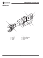
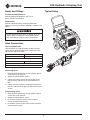
Identification
1. Crimping Head
2. Lock Pin
3. Cylinder
4. Trigger
5. Trigger Strap
6. Pressure (supply) Port
7. Tank (return) Port
8. Handle
1
8
2
4
5
3
7
6

LP6 Hydraulic Crimping Tool
Greenlee Tools, Inc. 4455 Boeing Dr. • Rockford, IL 61109-2988 USA • 815-397-7070
7
Specifications
LP6 Crimping Tool
Type of Hydraulic System: Open-center
or closed-center
Hydraulic Ports:
Pressure (supply): 3/4-16 UNF SAE O-ring Boss
Tank (return): 3/4-16 UNF SAE O-ring Boss
Noise Levels
L
WA
(Sound Power Level): 55.5 dB
L
pCpeak
(Peak Emission Sound Pressure Level):
68.8 dB
Vibration: 3.15 ms
2
Crimping Force: 53 kN (6 tons)
Length:
With Couplers: 597 mm (23.50")
Without Couplers: 527 mm (20.75")
Width: 76 mm (3.00")
Depth: 165 mm (6.50")
Mass/Weight: 4.2 kg (9.25 lb)
Hydraulic Power Source
Do not exceed the following hydraulic power source
maximums:
• Hydraulic ow: 34.1 l/min (9 gpm).
• Pressure relief setting: 172 bar (2500 psi).
• Back pressure: 13.8 bar (200 psi)
Failure to observe this warning could result in severe
injury or death.
Type of Hydraulic System: Open-center
or closed-center
Flow:
Minimum: 11.4 l/min (3 gpm)
Recommended: 22.7 l/min (6 gpm)
Maximum: 34.1 l/min (9 gpm)
Pressure Relief Setting:
Minimum: 103 bar (1500 psi)
Maximum: 172 bar (2500 psi)
Filtration: 10 micron (nominal)
Back Pressure (maximum*): 13.8 bar (200 psi)
* 13.8 bar (200 psi) is the maximum agreed standard back pressure
for the HTMA (Hydraulic Tool Manufacturers Association).
Greenlee Utility tools will operate satisfactorily at this standard.
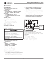
1. Maximum hydraulic uid temperature must not
exceed 60 °C (140 °F). A sufcient oil cooling
capacity is needed to limit the hydraulic uid
temperature.
2. Hydraulic ow must not exceed 34.1 l/min (9 gpm).
Install a ow meter in the return line to measure the
rate of hydraulic ow before using the tool.
3. Pressure relief valve setting must not exceed
172 bar (2500 psi) at your tool’s maximum ow.
Locate the pressure relief valve in the supply circuit
to limit excessive hydraulic pressure to the tool.
Hydraulic Schematic
FILTER
(10 MICRON)
COOLER
RELIEF
VALVE
172 bar
(2500 psi)
CONTROL
VALVE
FLOW METER
T
P
TOOL
RESERVOIR
PUMP
POWER SOURCE
Recommended Hydraulic Fluids
Use any nondetergent, petroleum-based hydraulic
uid which meets the following specications or HTMA
specications.
S.U.S. @:
38 °C (100 °F): 140 to 225
99 °C (210 °F): 40 minimum
Flash Point: 170 °C (340 °F) minimum
Pour Point: –34 °C (–30 °F) minimum

LP6 Hydraulic Crimping Tool
Greenlee Tools, Inc. 4455 Boeing Dr. • Rockford, IL 61109-2988 USA • 815-397-7070
8
Hoses and Fittings
Installation and Maintenance
Refer to publication 99930323, SAE J1273
(Hose and Hose Assemblies).
Replacement
Refer to a Greenlee Utility catalog or publication
99910322, Low Pressure Quick Couplers, Adapters and
Hoses.
Do not disconnect tool, hoses, or ttings while the
power source is running or if the hydraulic uid is
hot. Hot hydraulic uid can cause serious burns.
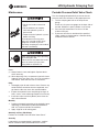
Hose Connections
Tool Port Identification
Three methods are used to identify the pressure and
return ports of Greenlee Utility tools. Match the mark-
ings on your tool to this table.
Pressure Port Return Port
P T
or
In Out
or
3/4–16 O-ring Boss
Connecting Hoses
1. Move the ow control lever on the hydraulic power
source to the OFF position.
2. Stop the hydraulic power source.
3. Connect the return hose to the return port on the
power source, and then to the return port on the
tool.
4. Connect the pressure hose to the pressure port on
the tool, and then to the pressure port on the power
source.
Disconnecting Hoses
1. Move the ow control lever on the hydraulic power
source to the OFF position.
2. Stop the hydraulic power source.
3. Disconnect the pressure hose from the power
source, and then from the tool.
4. Disconnect the return hose from the tool, and then
from the power source.
Typical Setup

LP6 Hydraulic Crimping Tool
Greenlee Tools, Inc. 4455 Boeing Dr. • Rockford, IL 61109-2988 USA • 815-397-7070
9
Operation
Electric shock hazard:
This tool is not insulated. When
using this unit near energized
electrical lines, use only certied
non-conductive hoses and proper
personal protective equipment.
Failure to observe this warning
could result in severe injury or death.
Skin injection hazard:
• Do not use hands to check for
leaks.
• Do not hold hose or couplers
while the hydraulic system is
pressurized.
• Depressurize the hydraulic system
before servicing.
Oil under pressure easily punc-
tures skin, causing serious injury,
gangrene, or death. If you are
injured by escaping oil, seek medical
attention immediately.
Wear eye protection when operating
or servicing this tool.
Failure to wear eye protection could
result in serious eye injury from
ying debris or hydraulic oil.
Keep hands away from the crimping
tool head when crimping.
Failure to observe this warning
could result in severe injury or death.
An incomplete crimp can cause a re.
• Use proper die, connector, and cable combina-
tions. Improper combinations can result in an
incomplete crimp.
• The relief valve sounds to indicate a completed
crimp. If you do not hear the sound of the relief
valve, the crimp is not complete.
Failure to observe these warnings could result in
severe injury or death.
1. Refer to the connector manufacturer’s instructions
for cable preparation and the crimping procedure.
2. Center the connector between the dies or nibs.
3. Press the trigger to advance the dies or nibs.
• Press the trigger down completely for fast
advance.
• Press the trigger down partially for slow advance.
4. Continue crimping until the pressure relief valve
activates.
Note: Pressure relief is indicated by a change in the
sound from the crimping tool and a sudden stiffen-
ing of the hydraulic hoses.
5. After achieving pressure relief, release the trigger.
The dies retract.
6. Complete the number of crimps specied by the
connector manufacturer.
7. When the tool is not in use, stop the power source
to reduce heat and wear on tool components.

LP6 Hydraulic Crimping Tool
Greenlee Tools, Inc. 4455 Boeing Dr. • Rockford, IL 61109-2988 USA • 815-397-7070
10
Operation (cont’d)
Die Selection
Interchangeable dies may be used in the standard die
opening. Dies that may be used include:
• Greenlee KD6 series
• Burndy W and X series
• ILSCO ND series
• Huskie HT58 series
• Panduit CD-2001 series
• Other industry W-type dies
Installing Dies
1. Select the proper dies for the connector to be
crimped.
2. Install dies in jaws making certain that they are
properly secured by the spring-loaded, positive
lock, die buttons.
Preparing Cable
Follow the lug manufacturer’s instructions for appropri-
ate cable strip length.
Crimping Direction
First Compression
Crimping Direction
SIDE A
Crimping Direction
SIDE B
First Compression
SIDE A
First Compression
SIDE B
Crimping Procedure
1. Insert conductor into the connector and align the
tool and die on the connector. Start in the center for
splices and “H” frames; and on the end, nearest the
pad, for terminals.
2. Activate the tool by pulling the trigger.
3. Continue crimping the connector until the correct
number of crimps has been completed. Work from
the center to the outer edges for splices and “H”
frame connectors, alternating sides if possible, for
the best compression connections.
An incomplete crimp can cause a re.
• Use proper die, connector, and cable combina-
tions. Improper combinations can result in an
incomplete crimp.
• The relief valve sounds to indicate a completed
crimp. If you do not hear the sound of the relief
valve, the crimp is not complete.
Failure to observe this warning could result in severe
injury or death.

LP6 Hydraulic Crimping Tool
Greenlee Tools, Inc. 4455 Boeing Dr. • Rockford, IL 61109-2988 USA • 815-397-7070
11
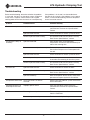
Maintenance
Skin injection hazard:
• Do not use hands to check for
leaks.
• Do not hold hose or couplers
while the hydraulic system is
pressurized.
• Depressurize the hydraulic system
before servicing.
Oil under pressure easily punc-
tures skin, causing serious injury,
gangrene, or death. If you are
injured by escaping oil, seek medical
attention immediately.
Wear eye protection when operating
or servicing this tool.
Failure to wear eye protection could
result in serious eye injury from
ying debris or hydraulic oil.
Notes:
(1) Keep all decals clean and legible. Replace decals
when necessary.
(2) When disposing of any components (hydraulic hoses,
hydraulic fluid, worn parts, etc.), do so in accordance
with federal, state and local laws or ordinances.
Daily
1. Thoroughly wipe all tool surfaces clean. Remove any
oxide inhibitor, connector contact compound, and
grit from the die seat areas, dies and die holders.
2. Inspect the hydraulic hoses and ttings for signs of
leaks, cracks, wear or damage. Replace if necessary.
3. Install dust caps over the hydraulic ports when the
tool is disconnected.
Monthly
1. Perform a thorough inspection of the hydraulic hoses
and ttings as described in publication 99930323,
SAE J1273 (Hose and Hose Assemblies).
2. Apply a light oil to all moving parts.
Quarterly or Every 500 Crimps
Perform the “Periodic Pressure Relief Valve Check.”
Annually
If required by your organization’s regulations, send the
tool to a Greenlee Utility Authorized Service Center.
Periodic Pressure Relief Valve Check
Test the crimping tool periodically to ensure that the
pressure relief valve activates at the proper pressure.
1. Test the crimping tool with an in-line pressure
gauge.
Install an in-line pressure gauge on the input side of
the tool. With dies in place, perform a test crimp.
2. Pressure relief should occur at 103 to 107 bar
(1500 to 1550 psi).
3. If pressure relief occurs outside of the specied
range, send the crimping tool to a Greenlee Utility
Authorized Service Center.

LP6 Hydraulic Crimping Tool
Greenlee Tools, Inc. 4455 Boeing Dr. • Rockford, IL 61109-2988 USA • 815-397-7070
12
Problem Probable Cause Probable Remedy
Tool does not operate. Improper power source. Verify that the power source meets the
specications. Refer to the “Specications”
section.
Hydraulic uid level low. Check the uid level. Check system for leaks.
Incorrect hydraulic uid viscosity. Use hydraulic uid with the correct viscosity.
Refer to the “Specications” section.
Tool operates slowly or
erratically.
Hydraulic uid cold. Allow uid to warm to the operating
temperature. Actuate the tool intermittently to
reduce the warming time.
Power source not adjusted correctly. Refer to the power source operator’s manual.
Set the ow and pressure to correspond with
the tool.
Hydraulic uid level low. Check the uid level. Check system for leaks.
Air in the hydraulic system. Refer to the power source manufacturer’s
instructions for removing air from the system.
Incorrect hydraulic uid viscosity. Use hydraulic uid with the correct viscosity.
Refer to the “Specications” section.
Tool feels hot. Hydraulic uid level low. Check the uid level. Check for leaks.
Incorrect hydraulic uid viscosity. Use hydraulic uid with the correct viscosity.
Refer to the “Specications” section.
Hydraulic uid dirty. Refer to the power source owner’s manual for
procedure to replace hydraulic oil and lter.
Tool operates backward. Hose connections at tool are
reversed.
Depressurize the hydraulic system. Switch the
hose connections.
Crimping tool does not
achieve pressure relief.
Improper power source. Verify that the power source meets the
specications. Refer to the “Specications”
section.
Dies do not retract. Dies caught on crimped connector. Twist crimping tool from side to side to free it
from the connector.
Excessive system back pressure. Troubleshoot the hydraulic system.
Troubleshooting
Before troubleshooting, determine whether the problem
is in the tool, the hoses, or the power source. Substitute
a tool, hoses, or power source known to be in good
working order to eliminate the item that is not operating.
If the problem is in the tool, see the troubleshoot-
ing table in this manual. If the problem is in the power
source, see the troubleshooting section of the power
source instruction manual.

LP6 Hydraulic Crimping Tool
Greenlee Tools, Inc. 4455 Boeing Dr. • Rockford, IL 61109-2988 USA • 815-397-7070
13
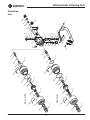
Illustration
Main
12
11A
13
51
15
36
38
32
33
34
50
37
39
35
31A
13
40
14
17
20
22
24
18
19
26
27
29
28
30
10
3
9
10
8
3
2
3
3
7
16
23
24
21
6
5
4
7
25
1
12
11B
13
51
15
36
38
32
33
34
50
37
39
35
31B
43
42
41
Open-Center
Closed-Center

LP6 Hydraulic Crimping Tool
Greenlee Tools, Inc. 4455 Boeing Dr. • Rockford, IL 61109-2988 USA • 815-397-7070
14
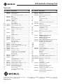
Illustration
Ram Unit
90
91
92
93
94
95
97
103
102
98
99
96
100
101

LP6 Hydraulic Crimping Tool
Greenlee Tools, Inc. 4455 Boeing Dr. • Rockford, IL 61109-2988 USA • 815-397-7070
15
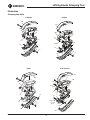
Illustration
Crimping Jaw Units
CJD3O
118A
113
110C
111
115
113
114
118A
116
117
CJD3
110D
114
113
115
118C
111
118C
116
117
CJD3BG
118A
118A
110A
114
115
113
116
117
111
CJK Kearney
119
121
120
117
116
111
115
118B
117
114
115
glued in with
Loctite 270
(green)
119
113
116
120
110B
118B

LP6 Hydraulic Crimping Tool
4455 Boeing Drive • Rockford, IL 61109-2988 • USA • 815-397-7070
©2019 Greenlee Tools, Inc. • An ISO 9001 Company
USA Tel: 800-435-0786
Fax: 800-451-2632
Canada Tel: 800-435-0786
Fax: 800-524-2853
International Tel: +1-815-397-7070
Fax: +1-815-397-9247
www.greenlee.com
Key Part No. Description Qty Key Part No. Description Qty
1 52062991 Handle, machined ..................................... 1
2 50436996 Strap, trigger ............................................. 1
3 Screw, cap-skt btn hd (#10-32 x .375) ...... 4
4 50418730 Ball ............................................................. 1
5 50492349 Stop, ball ................................................... 1
6 Ring, retaining ........................................... 1
7 50414323 Plug, plastic ............................................... 2
8 50425760 Trigger ........................................................ 1
9 Pivot, trigger .............................................. 1
10 Ring, retaining ........................................... 2
11A 52065313 Tube, return (O-C only) .............................. 1
11B 52062719 Tube, center (C-C only).............................. 1
12* O-ring ........................................................ 1
13* Ring, retaining (qty 2 for O-C) ................... 1
14 50425441 Retainer, seal (O-C only) ........................... 1
15* O-ring ........................................................ 1
16* O-ring ........................................................ 1
17 52063245 Spool ......................................................... 1
18* O-ring ........................................................ 1
19* O-ring, packing .......................................... 1
20 50435566 Plug ........................................................... 1
21 50410952 Cap ............................................................ 1
22 50434012 Washer....................................................... 1
23 50428651 Spring, valve-plunger ................................ 1
24 Ring, retaining ........................................... 2
25 Plug, pipe-coated ...................................... 2
26 50301462 Pin, valve ................................................... 1
27 50406921 Spring, valve-unloading ............................. 1
28 50482610 Screw, set-adjusting (1/2-20 x 1.00) ......... 1
29 50406461 Washer, copper ......................................... 1
30 50482602 Cap ............................................................ 1
31A 52064083 Piston (O-C only) ....................................... 1
31B 52062762 Piston (C-C only) ....................................... 1
32* O-ring (1-1/2 x 1-7/8 x 3/16 nitrile) ............ 1
33* O-ring (11/16 x 7/8 x 3/32 nitrile)............... 1
34* Ring, backup ............................................. 2
35 52062768 Cylinder sleeve .......................................... 1
36 52062763 Cylinder ..................................................... 1
37 52062764 Cap ............................................................ 1
38* O-ring (2-3/8 x 2-1/2 x 1/16) ..................... 1
39* O-ring (26 x 30 x 2) .................................... 1
40 50425431 Seal, bypass (O-C only) ............................. 1
41 50426851 Carrier, seal (C-C only) .............................. 1
42 50413313 O-ring (3/8 x 1/2 x 1/16) (C-C only) ........... 1
43 50435450 Ring, backup (C-C only) ............................ 2
52064101 Decal kit (includes 50–52)
50 Decal, Greenlee Utility ............................... 1
51 Decal, warning ........................................... 1
52 Decal, pinch hazard warning
(not shown) ................................................ 1
52048133 Ram unit (includes 90–103) ...................... 1
90 52049292 Sheath ....................................................... 1
52049399 Spring kit (includes 91–95)
91 Bolt, shoulder ............................................ 1
92 Disc............................................................ 1
93 Compression spring .................................. 1
94 Washer....................................................... 1
95 O-ring ........................................................ 1
52057497 Jaw holder kit (includes 90, 96, 97) ........... 1
96 52057496 Screw......................................................... 1
97 Jaw holder ................................................. 1
52049400 Latch kit (includes 98–101)
98 Compression spring .................................. 1
99 Locking pin ................................................ 1
100 Compression spring .................................. 1
101 Pin ............................................................. 1
52049401 Roller kit (includes 102 and 103)
102 Roller ......................................................... 2
103 Ram ........................................................... 1
52027121 CJD3BG crimping jaw unit
(includes
110
–
118)
52027122 CJD3O crimping jaw unit
(includes 110–118)
52024068 CJD3 crimping jaw unit (includes 110–118)
52020114
CJK Kearney crimping jaw unit
(includes 110–118, 119-121)
110A Jaw, CJD3BG ............................................ 2
110B Jaw, CJK ................................................... 2
110C Jaw, CJD3O .............................................. 2
110D Jaw, CJD3 ................................................. 2
111 52022544 Extension spring ........................................ 1
52049402 Jaw pivot kit (includes 113 and 114)
113 Retaining ring ............................................ 2
114 Pin pivot..................................................... 1
115 Bushing ..................................................... 2
116 Compression spring .................................. 2
117 Lock adapter ............................................. 2
118A 52025125 Jaw covers, CJD3O/CJD3BG (set of 2) .... 1
118B 52022386 Jaw covers, CJK (set of 2) ......................... 1
118C 52021086 Jaw covers, CJD3 (set of 2) ...................... 1
119 Bushing ..................................................... 2
120 Ball, 3 mm ................................................. 2
121 Locking pin ................................................ 1
50103750 Die pin kit, “W”-style dies
(includes 115–117)
50105108 Die pin kit, Kearney-style dies
(includes 116, 119–121)
52064102 Hardware kit (includes 3, 6, 9, 10,
13, 24, and 25)
* 52064103 Seal kit (includes items marked
with an asterisk)
Parts List
-
 1
1
-
 2
2
-
 3
3
-
 4
4
-
 5
5
-
 6
6
-
 7
7
-
 8
8
-
 9
9
-
 10
10
-
 11
11
-
 12
12
-
 13
13
-
 14
14
-
 15
15
-
 16
16


Greenlee LP6 is a hydraulic crimping tool intended to crimp connectors onto electrical cables, including:
- removable crimping jaws
- set for operation on an open-center or closed-center hydraulic system.
Ask a question and I''ll find the answer in the document
Finding information in a document is now easier with AI
Related papers
-
Greenlee LP6 User manual
-
-
-
-
-
-
-
-
-
Textron F13 Portable Power Unit S/C GMZ User manual
Other documents
-
 Eclipse Tools 902-480 User manual
-
Thomas & Betts Gator EK22GL User manual
-
 HYCLAT HWC007000 User manual
-
Powers 744 Installation guide
-
Eclipse 902-544 User manual
-
 Huskie Tools IL-MK7ND User manual
-
 Huskie Tools SL-MK7ND User manual
-
Apollo Conbraco 77WLF14601 Installation guide
-
 Huskie Tools SL-MKC7510 User manual
-
 Huskie Tools REC-MK7430 User manual


