Page is loading ...

Model D4646
Hose Reel
Instruction Sheet
Phone #: (360) 734-3482 • Online Tech Support: tech-support@shopfox.biz • Web: www.shopfox.biz
COPYRIGHT © SEPTEMBER, 2017 BY WOODSTOCK INTERNATIONAL, INC.
WARNING: NO PORTION OF THIS MANUAL MAY BE REPRODUCED IN ANY SHAPE OR FORM WITHOUT
THE WRITTEN APPROVAL OF WOODSTOCK INTERNATIONAL, INC.
Printed in China
#19185ES
To reduce the risk of injury when using this
tool:
• Make sure the incoming air pressure does
not exceed the maximum rating of 300
PSI for the reel or hose/accessory you are
using. Otherwise, the fittings could crack
or explode.
• Protect your eyes by wearing safety glass-
es or a face shield when assembling,
mounting and using the hose reel.
• Pressurized air may cause injury to
exposed body parts. Never expose any
part of your body to pressurized air.
• Make sure the hose reel is firmly mounted
to a stable surface before pressurizing.
• Do not allow children to use the hose
reel. Keep children clear of the work
area.
Specifications
Max. Incoming Air Pressure ................. 300 PSI
Max. Hose Length ............... 50 ft. of
3
⁄8" Hose
Air Fitting Size ...............................
1
⁄4" NPT
Maximum Air Flow ........................... 25 CFM
Items Needed
Open-End Wrench 13mm............................1
Open-End Wrench 15mm............................1
Open-End Wrench 8mm .............................1
Adjustable Wrench ...................................1
Phillips Head Screwdriver Stubby #2 .............1
Air Compressor .......................................1
Air Hose (Connects Compressor/Hose Reel) .....1
Fasteners
7
⁄16"............................. As Needed
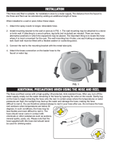
Figure 1. Model D4646.
Mounting
1. Choose a location for mounting the hose
reel to a wall, floor, ceiling, etc. that uses
a load-bearing structural member capable
of supporting the combined weight of the
reel, hose and any forces applied to it.
— If you plan to install the hose reel on a
ceiling, place it 10 feet above the floor.
Inventory
The Model D4646 is shipped fully assembled, as
shown in Figure 1.

-2-
D4646 Hose Reel Instructions
Operation
1. Slowly pull the hose out of the reel
assembly until you hear a "click."
2. To lock the hose, let it retract after you
hear the reel click.
3. To unlock the hose, slowly pull the hose out
until you hear no more clicking, then, while
holding onto the hose, let it draw back
until the bumper stops against the hose
guide.
2. Check that the hose guide roller bracket
position (see Figure 2) is suitable for the
chosen mounting position.
—If the roller bracket or hose guide roller
position is not in the best position, refer
to Changing Roller Bracket Position.
3. Mark the location of the mounting slots on
the reel base (see Figure 2) in the chosen
location, then secure with (4) 7⁄16" grade 5
fasteners.
4. Remove the plastic plug from the inlet
valve (see Figure 3), apply Teflon pipe
tape or thread sealant to the threads of
the incoming air hose (not included), then
connect it to the inlet valve.
6. Apply Teflon pipe tape or thread sealant to
the outlet hose threads, then attach the
tool or nozzle.
7. Turn the air pressure ON, then use soapy
water to test for leaks. If any are found,
turn the air pressure OFF, relieve the
pressure from the hose, then repair the
leaks before putting the hose reel into
operation.
8. To adjust the hose bumper (see Figure 2),
pull some hose out until it clicks in place,
loosen the screws on the bumper, slide it
close to the hose guide, then tighten the
screws.
Figure 2. Roller bracket and main components.
Hose
Guide
Bumper
Roller
Bracket
Outlet
Inlet
Valve
5. Connect the other end of the incoming air
hose to the compressor, if you have not
already done so.
Changing Roller Bracket Position
1. To change the hose guide roller bracket
position, pull out some hose until you hear
a "click" to lock it.
2. Remove (4) lock nuts and carriage bolts
on the roller bracket (see Figure 2),
rotate the bracket to any of the alternate
positions, then re-install the carriage bolts
and lock nuts.
NOTICE
To avoid damaging the hose reel, always
hold onto the hose while it is rewinding.
Figure 3. Location to connect incoming air
hose.
Mounting Slot
(1 of 4)
Lock Nuts
(1 of 4)

-3-
D4646 Hose Reel Instructions
Replacing Hose
1. DISCONNECT THE AIR SUPPLY FROM THE
HOSE REEL!
2. Unwind the hose completely, lock it in
place, making sure it will not rotate
backward, then remove the bumper.
Adjusting Spring Tension
1. DISCONNECT THE AIR SUPPLY FROM THE
HOSE REEL!
2. Pull approximately 2 feet of the hose out
and lock it.
3. Remove the bumper from the hose. Unlock
the reel and, while holding onto the drum
edge, allow the drum to unwind and thread
the hose out of the guide.
4. Lock the hose reel.
5. To increase tension on the hose, unlock
it and turn the drum clockwise (as
viewed from the inlet valve); to decrease
tension, unlock it, then turn the drum
counterclockwise.
6. When the desired tension is achieved, lock
the hose reel, re-insert the hose through
the guide, then re-install the bumper on
the hose.
7. Unlock the hose and check the tension.
Adjust the position of the bumper if
needed.
8. Connect the incoming air supply to the
inlet valve.
4. Using an adjustable wrench, unthread the
hose from the inlet valve, then remove the
hose through the drum opening and hose
guide.
5. Remove the hose clamp and spring guard
from the old hose, then replace them on
the new hose in the same location.
6. Apply Teflon tape to the threads of the
incoming end of the new air hose, then
thread the hose into the inlet valve.
7. Unwind any kinks in the new hose.
8. Feed the new hose through the drum
opening, then position the spring guard
over the drum opening.
9. Fasten the hose clamp onto the hose reel
with the screws and nuts removed in
Step 3.
10. Re-install the bumper on the hose where it
was previously located, release the hose,
and slowly allow it to wind back onto the
reel.
11. Re-adjust spring tension as needed (refer to
Adjusting Spring Tension).
3. Remove the screw and nut that mount the
hose clamp to the drum (see Figure 4).
Figure 4. Component locations for removing
hose.
Inlet
Valve
Spring
Guard
Drum
Opening
Hose
Clamp

-4-
D4646 Hose Reel Instructions
Parts Breakdown & List
1
2
3
4
5
6
7
8
9
10
11
12
13
14
15
16
17
18
19
20
21
22
23
24
25
26
27
28
29
30
31
32
33
34
35
36
37
38
39
40
41
42
43
44
MODEL D4646
HOSE REEL 3/8" x 50'
WARNING!
To reduce the risk of serious personal injury during use:
1. Read and understand the manual before starting or
servicing.
2. Disconnect from air supply before servicing.
3. Wear ANSI-approved eye protection.
4. DO NOT exceed the maximum pressure rating of 300 PSI
for this reel or the pneumatic accessory you are using.
5. Only use flexible hose to attach this hose reel to the air
supply. Solid pipe may fail due to vibrations caused
during reeling of the hose.
UNWIND
REF PART # DESCRIPTION REF PART # DESCRIPTION
1 XD4646001 OUTSIDE SPRING COVER 23 XD4646023 LOCKING GEAR MOUNT
2 XD4646002 MAIN SPRING 24 XD4646024 LOCKING GEAR
3 XD4646003 INSIDE SPRING COVER 25 XD4646025 AXLE
4 XD4646004 OUTSIDE DRUM 26 XD4646026 LOCKING CAM
5 XD4646005 INSIDE DRUM 27 XD4646027 EXTENSION SPRING
6 XD4646006 BASE 28 XD4646028 FLAT WASHER 10MM
7 XD4646007 ROLLER BRACKET 29 XD4646029 HEX NUT M10-1.5
8 XD4646008 HOSE GUIDE BACK PLATE 30 XD4646030 FLAT WASHER 16MM
9 XD4646009 HOSE GUIDE BRACKET 31 XD4646031 HEX NUT M16-1.5
10 XD4646010 HOSE GUIDE ROLLERS 4PC 32 XD4646032 CARRIAGE BOLT M8-1.25 X 18
11 XD4646011 AIR INLET 3/8" 33 XD4646033 LOCK NUT M8-1.25
12 XD4646012 SWIVEL CONNECTOR 3/8" 34 XD4646034 HEX BOLT M8-1.25 X 16
13 XD4646013 EXT RETAINING RING 18MM 35 XD4646035 LOCK NUT M8-1.25
14 XD4646014 SWIVEL CONNECTOR WASHER 18MM 36 XD4646036 PHLP HD SCR M5-.8 X 10
15 XD4646015 LOCK NUT M6-1 37 XD4646037 LOCK NUT M5-.8
16 XD4646016 STANDOFF STUD M6-1 X 57 38 XD4646038 HOSE BUMPER 2PC
17 XD4646017 LOCK NUT M6-1 39 XD4646039 PHLP HD SCR M6-1 X 25
18 XD4646018 HOSE CLAMP 40 XD4646040 HEX NUT M6-1
19 XD4646019 PHLP HD SCR M5-.8 X 10 41 XD4646041 HOSE 3/8" X 50'
20 XD4646020 HEX NUT M5-.8 42 XD4646042 ID LABEL
21 XD4646021 CARRIAGE BOLT M6-1 X 45 43 XD4646043 SHOP FOX LOGO LABEL
22 XD4646022 LOCK NUT M6-1 44 XD4646044 HOSE DIRECTION LABEL
Parts information is provided for
service purposes only. Not all
parts are available for purchase.
For questions contact Woodstock International Technical Support at (360) 734-3482, or send e-mail to:
tech-support@woodstockint.com.
/