16
Vent Pipe Installation
Chapter4.–Installation
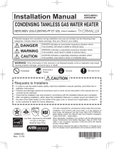
HorizontalVentTermination-PVC/CPVCMaterialsOnly
• As illustrated on the right, make sure to keep a distance of 3'
(0.9m) or wider between the intake and exhaust when installing the
vent piping.
* If 3' (0.9m) remote distance between Intake and Exhaust cannot
be ensured, the installation can be carried out only in the installa-
tion method shown in page 18.
• The PVT-HL termination may be used in place of elbows as the
horizontal vent terminations. It is not necessary to use bird screens
with the PVT-HL termination.
• Terminate at least 12" (300mm) above grade or above snow line.
• Terminate at least 7' (2.1m) above a public walkway, 6' (1.8m)
from the combustion air intake of any appliance, and 3' (0.9m) from
any other building opening, gas utility meter, service regulator etc.
• Terminate at least 3' (0.9m) above any forced air inlet within 10'
(3m) , 1' (0.3m) below, 1' (0.3m) horizontally from or 1' (0.3m)
above any door, window, or gravity air inlet into any building per
National Fuel Gas Code ANSI Z223.1/NFPA 54.
• Slope the horizontal vent 1/4" upwards for every 12" (300mm)
toward the termination.
• Use a condensation drain if necessary.
• In the Commonwealth of Massachusetts a carbon monoxide de-
tector is required for all side wall horizontally vented gas fuel equip-
ment. Please refer to Technical Bulletin TB 010606 for full installa-
tion instructions.
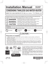
VerticalVentTermination-PVC/CPVCMaterialsOnly
• As illustrated on the right, make sure to keep a distance of 3'
(0.9m) or wider between the intake and exhaust
when installing the vent piping.
• Terminate at least 6' (1.8m) from the combustion air intake of any
appliance, and 3' (0.9m) from any other
building opening, gas utility meter, service regulator etc.
• Enclose exterior vent systems below the roof line to limit conden-
sation and protect against mechanical failure.
• When the vent penetrates a oor or ceiling and is not running in a
re rated shaft, a restop and support is
required.
• When the vent termination is located not less than 8' (2.4m) from
a vertical wall or similar obstruction,
terminate above the roof at least 2' (0.6m), but not more than 6'
(1.87m), in accordance with the National
Fuel Gas Code ANSI Z223.1/NFPA 54.
• Provide vertical support every 3' (0.9m) or as required by the vent
pipe manufacturer’s instructions.
• A short horizontal section is recommended to prevent debris from
falling into the water heater.
• When using a horizontal section, slope the horizontal vent 1/4"
upwards for every 12" (300mm) toward the
termination to drain condensate.
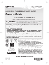
When choosing intake and exhaust terminations, you must use the
same type of elbow (i.e. both 90° elbows).
This will help with proper combustion by putting both terminations in
the same pressure zone.
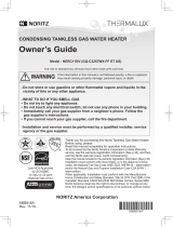
When choosing intake and exhaust terminations, you must
use the same type of elbow (i.e. both 90° elbows).
This will help with proper combustion by putting both
terminations in the same pressure zone.
Vent Pipe Installation (DV-Direct Vent)
l
p
zG
|
QQXNGOWUZPGt
QGuGGG
GGSGG
QQXNGOWUZPGt
GGGSGGGU
o
z
ZIGt
pGiGzQ
GlGG`WGGl
l
p
zG
|
QQXNGOWUZPGt
QGuGGG
GGSGG
QQXNGOWUZPGt
GGGSGGGU
o
z
m
z
mVz
z
j
y
m
pGi
zQG
lGG`WGGl
m
y
m
z
j
XYIGG
G
GY[ISG
GU
ZUGtU
XYIG
GGY[IS
G
U
l
p
zG
|
QQXNGOWUZPGt
QGuGGG
GGSGG
QQXNGOWUZPGt
GGGSGGGU
o
z
ZIGt
pGiGzQ
GlGG`WGGl
l
p
zG
|
QQXNGOWUZPGt
QGuGGG
GGSGG
QQXNGOWUZPGt
GGGSGGGU
o
z
m
z
mVz
z
j
y
m
pGi
zQG
GGl
m
y
m
z
j
G
GU
ZUGtU
XYIGG
GGY[IS
G
U