Hampton Bay 20010 Installation guide
- Category
- Household fans
- Type
- Installation guide
This manual is also suitable for


®
Item #1002 706 090, 1002 707 960
Model #91350, 91359
UL Model #52-BVD
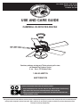
USE AND CARE GUIDE
CAMPBELL 52-INCH CEILING FAN
Questions, problems, missing parts? Before returning to the store,
call Hampton Bay Customer Service
8 a.m. - 6 p.m., EST, Monday-Friday
1-855-HD-HAMPTON
HAMPTONBAY.COM
THANK YOU
We appreciate the trust and condence you have placed in Hampton Bay through the purchase of this ceiling fan. We strive to continually create
quality products designed to enhance your home. Visit us online to see our full line of products available for your home improvement needs.
Thank you for choosing Hampton Bay!
To view an instructional video on how to install this product:
1. Go to www.homedepot.com and enter either the Item or Model number, found in the top
right corner of the cover of this instruction manual, in the search eld.
2. Click on your product from the list of search results and click on the video link in the
“Product Overview” section.

2
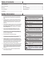
Table of Contents ................................................................2
Safety Information ...............................................................2
Warranty ............................................................................... 3
Pre-Installation ....................................................................3
Installation ............................................................................6
Assembly ..............................................................................7
Operation ...........................................................................15
Care and Cleaning ............................................................. 16
Troubleshooting .................................................................16
1. To reduce the risk of electric shock, ensure the electricity has
been turned off at the circuit breaker or fuse box before you
begin.
2. All wiring must be in accordance with the National Electrical
Code ANSI/NFPA 70-1999 and local electrical codes. Electrical
installation should be performed by a qualified licensed
electrician.
3. The outlet box and support structure must be securely mounted
and capable of reliably supporting 35 lbs. (15.9 kg). Use only
UL Listed outlet boxes marked “Acceptable for Fan Support of
35 lbs. (15.9 kg) or less.”
4. The fan must be mounted with a minimum of 7 ft. (2.1 m)
clearance from the trailing edge of the blades to the oor.
5. Do not operate the reversing switch while the fan blades are
in motion. You must turn the fan off and stop the blades before
you reverse the blade direction.
6. Do not place objects in the path of the blades.
7. To avoid personal injury or damage to the fan and other items,
use caution when working around or cleaning the fan.
8. Electrical diagrams are for reference only. Light kits that are
not packed with the fan must be UL-listed and marked suitable
for use with the model fan you are installing. Switches must be
UL General Use Switches. Refer to the instructions packaged
with the light kits and switches for proper assembly.
9. After making electrical connections, spliced conductors should
be turned upward and pushed carefully up into the outlet box.
The wires should be spread apart with the grounded conductor
and the equipment-grounding conductor on one side of the
outlet box.
10. All setscrews must be checked and retightened where
necessary before installation.
WARNING: To reduce the risk of personal injury,
do not bend the blade brackets (also referred to as
anges) during assembly or after installation. Do not
insert objects in the path of the blades.
WARNING: Remove the rubber motor stops on
the bottom of the fan before installing the blades or
testing the motor.
WARNING: To reduce the risk of re or electric
shock, do not use this fan with any solid-state speed
control device.
WARNING: To avoid possible electrical shock,
turn the electricity off at the main fuse box before
wiring. If you feel you do not have enough electrical
wiring knowledge or experience, contact a licensed
electrician.
WARNING: Electrical diagrams are for reference
only. Optional use of any light kit shall be UL-listed
and marked suitable for use with this fan.
WARNING: To reduce the risk of re or electric
shock, this fan should only be used with fan speed
control part no. MR101D manufactured by Chungear
Industrial Co., LTD.
Safety Information
Table of Contents
WARNING: To reduce the risk of re, electric shock,
or personal injury, mount to outlet box marked
“Acceptable for fan support of 35 lbs. (15.9 kg) or
less,” and use the screws provided with the outlet
box.
CAUTION: Changes or modications not expressly
approved by the party responsible for compliance
could void the user’s authority to operate the
equipment.

3
HAMPTONBAY.COM
Please contact 1-855-HD-HAMPTON for further assistance.
Pre-Installation
Warranty
The supplier warrants the fan motor to be free from defects in workmanship and material present at time of shipment from the factory for a life-
time after the date of purchase by the original purchaser. The supplier also warrants that all other fan parts, excluding any glass or acrylic blades,
to be free from defects in workmanship and material at the time of shipment from the factory for a period of one year after the date of purchase
by the original purchaser. We agree to correct such defects without charge or at our option replace with a comparable or superior model if the
product is returned. To obtain warranty service, you must present a copy of the receipt as proof of purchase. All costs of removing and reinstall-
ing the product are your responsibility. Damage to any part, such as by accident, misuse, improper installation, or by afxing any accessories, is
not covered by this warranty. Because of varying climatic conditions this warranty does not cover any changes in brass nish, including rusting,
pitting, corroding, tarnishing, or peeling. Brass nishes of this type give their longest useful life when protected from varying weather conditions.
A certain amount of “wobble” is normal and should not be considered a defect. Servicing performed by unauthorized persons shall render the
warranty invalid. There is no other express warranty. Hampton Bay hereby disclaims any and all warranties, including but not limited to those
of merchantability and tness for a particular purpose to the extent permitted by law. The duration of any implied warranty which cannot be
disclaimed is limited to the time period as specied in the express warranty. Some states do not allow a limitation on how long an implied war-
ranty lasts, so the above limitation may not apply to you. The retailer shall not be liable for incidental, consequential, or special damages arising
out of or in connection with product use or performance except as may otherwise be accorded by law. Some states do not allow the exclusion of
incidental or consequential damages, so the above exclusion or limitation may not apply to you. This warranty gives specic legal rights, and you
may also have other rights which vary from state to state. This warranty supersedes all prior warranties. Shipping costs for any return of product
as part of a claim on the warranty must be paid by the customer.
Contact the Customer Service Team at 1-855-HD-HAMPTON or visit www.HamptonBay.com.
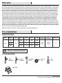
SPECIFICATIONS
TOOLS REQUIRED
Size Speed Volts Amps Watts RPM CFM
Net
Weight
Gross
Weight
Cube Feet
52 in.
Low
Medium
High
120
0.20
0.33
0.50
12
28
59
60
105
160
1772
2929
4258
18.3 lbs
(8.3 kg)
22.05 lbs
(10 kg)
1.6
NOTE: These are approximate measures. They do not
include the amps and wattage used by the light kit.
Phillips
screwdriver
Flat blade
screwdriver
Adjustable
wrench
Electrical
tape
Wire
cutter
Step ladder

4
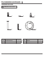
Part Description Quantity
AA Extra blade bracket screw 1
BB Extra lock washer 1
CC Plastic wire connector 3
Part Description Quantity
DD Hanger pin 1
EE Locking pin 1
FF Rubber gasket 1
Pre-Installation (continued)
HARDWARE INCLUDED
NOTE: Hardware not shown to actual size.
CC
DD
EE
AA
FF
BB

5
HAMPTONBAY.COM
Please contact 1-855-HD-HAMPTON for further assistance.
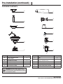
Part Description Quantity
A Slide-on mounting bracket
(inside canopy)
1
B Ball/downrod assembly 1
C Canopy 1
D Fan-motor assembly 1
E Light kit tter assembly 1
Part Description Quantity
F Blade 5
G Blade bracket
(with pre-installed screws)
5
H Glass shade 3
I LED bulbs (9 Watt maximum) 3
J Remote control (battery included) 1
K Receiver 1
IMPORTANT: This product and/or components are
governed by one or more of the following U.S. Patents:
5,947,436; 5,988,580; 6,010,110; 6,046,416, 6,210,117
and other patents pending.
Pre-Installation (continued)
PACKAGE CONTENTS
A
B
C
F
D
H
G
E
I
K
J

6
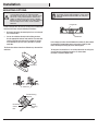
Installation
MOUNTING OPTIONS
WARNING: To reduce the risk of re, electric shock
or personal injury, mount to an outlet box marked
“Acceptable for fan support of 35 lbs. (15.9 kg) or less,”
and use the screws provided with the outlet box. An
outlet box commonly used for the support of lighting
xtures may not be acceptable for fan support and may
need to be replaced. If in doubt, consult a qualied
electrician.
If your ceiling fan does not have an existing UL-listed mounting
box, then install one using the following instructions:
□ Disconnect the power by removing the fuses or turning off
the circuit breakers.
□ Secure the outlet box directly to the building structure.
Use the appropriate fasteners and materials. The outlet box
and its bracing must be able to fully support the weight
of the moving fan (at least 35 lbs.). Do not use a plastic
outlet box.
The illustrations below show three different ways to mount the
outlet box.
If the canopy (C) touches the ball/downrod assembly (B), then remove
the decorative canopy bottom cover and turn the canopy (C) 180°
before attaching the canopy (C) to the mounting plate.
To hang your fan where there is an existing xture but no ceiling joist,
you may need an installation hanger bar as shown above
(available at any Home Depot store).
NOTE: You may need a longer downrod to maintain
proper blade clearance when installing on a steep, sloped
ceiling. The maximum angle allowable is 20° away from
horizontal.
Outlet Box
Outlet Box
Recessed
Outlet
Box
Provide Strong
Support
Ceiling
Mounting
Plate
Outlet Box
Hanger Bar

7
HAMPTONBAY.COM
Please contact 1-855-HD-HAMPTON for further assistance.
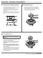
Routing the wires
Assembling the fan
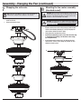
Preparing for standard mounting
□ Loosen, but do not remove, the setscrews (HH) on the collar
on top of the fan-motor assembly (D).
□ Align the holes at the bottom of the ball/downrod assembly
(B) with the holes in the collar on top of the fan-motor
assembly (D).
□ Carefully inset the hanger pin (DD) through the holes in
the collar and ball/downrod assembly (B). Be careful not to
jam the hanger pin (DD) against the wiring inside the ball/
downrod assembly (B).
□ Insert the locking pin (EE) through the hole near the end of
the hanger pin (DD) until it snaps into its locked position.
□ Re-tighten the setscrews (HH) on the collar on top of the
fan-motor assembly (D).
□ Remove the canopy ring (L) from the canopy (C) by turning
the ring counter-clockwise until it unlocks.
□ Remove the mounting bracket (A) from the canopy (C) by
loosening the two canopy screws (JJ) located in the “L
shaped” slots.
□ Remove and save the two canopy screws (II) in the round
holes. This will enable you to remove the mounting bracket
(A).
□ Make sure the slot openings are on top and route the
wires exiting the top of the fan-motor assembly (D)
through the canopy (C) and the canopy ring (L) and then
through the ball/downrod assembly (B).
2
3
1
A
C
II
L
JJ
C
B
D
L
B
D
DD
EE
HH
WARNING: Failure to properly install the locking pin (EE)
could result in the fan becoming loose and possibly
falling.
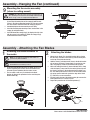
Assembly - Standard Ceiling Mount

8
□ Remove three of the six screws and lock washers (QQ) (every
other one) securing the motor collar (N) to the top of the fan-
motor assembly (D).
□ Place the rubber gasket (FF) over the remaining three screws,
route the wires exiting the top of the fan-motor assembly (D)
through the canopy (C) and canopy ring (L) (make sure the slot
openings are on top), and then place the canopy (C) over the
collar at the top of the fan-motor assembly (D).
□ Align the mounting holes with the holes in the motor and
fasten using the three screws and lock-washers (QQ) removed
previously. Tighten the mounting screws securely.
C
FF
D
QQ
N
L
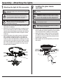
Attaching the fan to the electrical
box
□ Pass the 120-Volt supply wires through the center hole in the
slide-on mounting bracket (A).
□ Install the slide-on mounting bracket (A) on the outlet box by
sliding the slide-on mounting bracket (A) over the two screws (TT)
provided with the outlet box. If necessary, use leveling washers
(not included) between the slide-on mounting bracket (A) and
the outlet box. The at side of the slide-on mounting bracket (A)
should face toward the outlet box, as shown.
□ Securely tighten the two mounting screws (TT).
1
WARNING: To reduce the risk of re, electric shock
or personal injury, mount to an outlet box marked
“Acceptable for fan support of 35 lbs. (15.9 kg) or less,”
and use the screws provided with the outlet box.
A
TT
TT
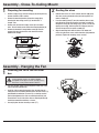
Routing the wiresPreparing for mounting
21
□ Remove canopy ring (L) from the canopy (C) by turning the ring
counter-clockwise until it unlocks.
□ Remove the mounting bracket (A) from the canopy (C) by
loosening the two canopy screws (JJ) located in the “L
shaped” slots
□ Remove and save the two canopy screws (II) in the round
holes. This will enable you to remove the mounting bracket (A).
□ Remove the decorative canopy bottom cover (M) from the
canopy (C) by pressing the three studs located inside the
bottom of the canopy.
M
A
C
II
L
JJ
Assembly - Close-To-Ceiling Mount
Assembly - Hanging the Fan

9
HAMPTONBAY.COM
Please contact 1-855-HD-HAMPTON for further assistance.
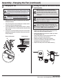
Hanging the fan
2
A
B
D
C
A
C
D
L
XX
Close to ceiling mount. Standard mount.
L
XX
Assembly - Hanging the Fan (continued)
□ Carefully lift the fan-motor assembly (D) up to the slide-on
mounting bracket (A).
□ Insert the ball portion of the ball/downrod assembly into the
socket of the slide-on mounting bracket.
□ Turn the ball/downrod assembly clockwise until it is seated
with the tab of the slide-on mounting bracket aligned with the
slot in the ball.
□ If using close-to-ceiling mounting, hang the fan on the hook
provided by utilizing one of the holes at the outer rim of the
ceiling canopy (C).
WARNING: The hook (XX) is only to balance the fan while
making the electrical connections. Failure to hang as shown
may result in the hook (XX) breaking, causing the fan to fall.
The hook must pass from the inside to the outside of the
canopy.
WARNING: When hanging the fan on the hook (XX) it is
critical that you use one of the non-slotted (round) holes in
the canopy (C).
3
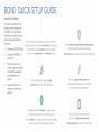
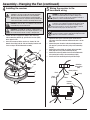
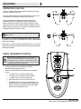
NOTE: The frequencies on your receiver and remote
control have been preset at the factory. Before installing
the receiver, make sure the dip switches on the receiver
and remote control are set to the same frequency. The dip
switches on the remote control are located inside the battery
compartment.
NOTE: The battery will weaken with age and should be
replaced before leaking takes place, as this will damage the
remote control. Dispose of used batteries properly and keep
batteries out of the reach of children.
Setting the code on the remote control
and receiver
J
K
1 2 3 4
ON
DIP
□ Remove the remote control (J) battery cover by pressing
rmly on the arrow and sliding the cover off.
□ Slide the dip switches to your choice of either up or down.
The factory setting is up.
□ Slide the dip switches on the receiver (K) to the same
position as set on the remote control (J).
NOTE: The switch marked ON/DIM controls the dimming
function of the lights: If using non-dimmable bulbs, use a
ballpoint pen or small screwdriver to set the switch to ON to
disable the dimming function. If using dimmable bulbs, set
the switch to DIM to enable the dimming function.
□ Remove the protective coating from the battery.
□ Install the 12-Volt battery (included) into the battery
compartment of the remote control (J).
□ Replace the battery cover on the remote control (J).

10
4
Assembly - Hanging the Fan (continued)
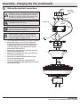
Installing the receiver
□ Position the house supply wires (AAA) to one side of the
slide-on mounting bracket (A); position the fan wires (BBB)
to the opposite side.
□ Insert the narrow end of the receiver (as shown, at side
towards the ceiling) into the slide-on mounting bracket until
it rests on top of the ball/downrod assembly.
WARNING: To reduce the risk of re or electric shock,
remember to disconnect power. The electrical wiring must
meet all local and national electrical code requirements.
The electrical source and fan must be 110/120 volt, 60Hz.
Do not use this product in conjunction with any variable wall
control. Incorrect wire connection can damage this receiver.
CAUTION: If other fan wires are a different color, have this
unit installed by a licensed electrician.
CAUTION: Do not install the receiver in a damp location or
immerse in water (For indoor use only). Do not pull on or cut
the receiver leads shorter. Do not drop or bump the unit.
AAA
C
B
K
BBB
A
L
5
Wiring the receiver to the
household wiring
IMPORTANT: Use the wire connecting nuts (CC) supplied with
your fan. Secure the connectors with electrical tape and ensure
there are no loose strands or connections.
WARNING: Each wire not supplied with this fan is designed to
accept up to one 12-gauge house wire and two wires from the
fan. If you have larger than 12-gauge house wiring or more
than one house wire to connect to the fan wiring, consult an
electrician for the proper size wire nuts to use.
□ Spread the wires apart so that the green and white wires
are on one side of the outlet box and the black wire is on the
other side.
□ Connect the green fan wires to the household ground wire
(this may be a green or bare wire) using a wire connecting
nut (CC).
□ Connect the receiver black (or red) wire to the household
black (hot) wire using a wire connecting nut (CC).
□ Connect the receiver (K) white wire to the household white
wire (neutral) wire using a wire connecting nut (CC).
□ Secure each wire connecting nut using electrical tape.
Black
(or Red)
White
Black
Green (or Bare)
Green
Outlet Box
in the ceiling
(MM)
Receiver
Antenna
White
Receiver (K)
CC (x3)
WARNING: To avoid possible electrical shock, turn the
electricity off at the main fuse box before wiring. If you
feel you do not have enough electrical wiring knowledge or
experience, contact a licensed electrician.

11
HAMPTONBAY.COM
Please contact 1-855-HD-HAMPTON for further assistance.
Making the electrical connections
□ The fan comes with 54 in. lead wires for use with an extended
ball/downrod assembly. If using the 4.5 in. ball/downrod
assembly (B) provided, you can cut the lead wires to your
desired length (no shorter than 12 in.) This will make extra
room in the canopy (C), if you do not wish to cut the wires,
you will need to neatly wrap them.
□ Connect the fan motor white wire to the receiver white wire
using a wire connecting nut (CC).
□ Connect the fan motor black wire to the receiver black wire
using a wire connecting nut (CC).
□ Connect the fan motor blue wire to the receiver blue wire
using a wire connecting nut (CC).
□ Secure each wire connecting nut using electrical tape.
□ Turn the wire connecting nut (CC) upward and push the wiring
into the outlet box (MM).
6
IMPORTANT: Use the plastic wire connectors (CC) supplied with
your fan. Secure the connectors with electrical tape and ensure
there are no loose strands or connections.
WARNING: Each wire connector supplied with this fan is
designed to accept up to one 12-gauge house wire and two wires
from the fan. If you have larger than 12-gauge house wiring or
more than one house wire to connect to the fan wiring, consult
an electrician for the proper size wire connectors to use.
Outlet box
in the ceiling
(MM)
Receiver (K)
Blue
Receiver
Antenna
Black White
Green
CC (x3)
CAUTION: If the supply wires are a different color, have this
unit installed by a licensed electrician.
Assembly - Hanging the Fan (continued)
NOTE: The fan comes with 54 inch lead wires for use with an
extended ball/downrod assembly. If using the 4.5 inch ball/
downrod assembly (B) provided, you can cut the lead wires to
your desired length (no shorter than 12 inches).

12
D
C
A
JJ
L
Mounting the fan-motor assembly
(standard mount)
□ Align the locking slots of the ceiling canopy (C) with the two
screws in the mounting bracket (A). Push up to engage the
slots and turn clockwise to lock in place.
□ Firmly tighten the two mounting screws.
□ Install the two mounting screws (saved from Assembly Step
1 “Prepairing for mounting”) into the holes in the canopy
(C) and tighten rmly.
□ Install the decorative canopy ring (L) by aligning the ring’s
slots with the screws in the canopy (C). Rotate the ring
clockwise to lock in place.
8
WARNING: When using the standard ball/downrod mounting, the
tab in the ring at the bottom of the mounting bracket must rest in
the groove of the hanger ball. Failure to properly seat the tab in
the groove could cause damage to the wiring.
Assembly - Hanging the Fan (continued)
Wrapping the extra wire
□ Gently wrap the excess wire around the mounting bracket,
under the receiver.
□ Secure with electrical tape.
7
NOTE: Follow this step ONLY if you did not cut the extra length off
from the wires coming from the ceiling fan to the receiver.
WARNING: The locking slots of ceiling canopy are provided only
as an aid to mounting. Do not leave the fan assembly unattended
until all four canopy screws are engaged and rmly tightened.

13
HAMPTONBAY.COM
Please contact 1-855-HD-HAMPTON for further assistance.
Attaching the blade brackets to
the motor
Attaching the blades
1 2
□ Mount the fan blade (F) to the blade bracket (G) by aligning
the three key-slot holes in the blade (F) with the three posts
on the top of the blade bracket (G).
□ Hold the blade (F) with both hands close to the blade bracket
(G) and press the blade (F) down rmly. Ensure the key-slot
holes are properly seated on the blade bracket (G) posts.
□ While still holding the blade (F) down with both hands, rmly
slide the blade (F) away from the fan-motor (D) housing until
the blade (F) engages in the locking mechanism. Make sure
the steel locking mechanism at the rear of the blade bracket
(G) springs upward and butts against the edge of the blade
(F), indicating a secure connection.
□ Visually inspect the top of the blade bracket (G) to ensure the
locking mechanism is securely in place.
□ Repeat this procedure for the remaining blades (F).
D
G
F
□ Carefully unhook the fan from the slide-on mounting bracket
(A) and align the locking slots of the canopy (C) with the two
screws in the slide-on mounting bracket (A). Push up to engage
the slots and turn clockwise to lock the canopy (C) in place.
□ Immediately tighten the two mounting screws rmly.
□ Install the remaining two mounting screws into the holes in the
canopy (C) and tighten rmly.
□ Install the decorative canopy ring (L) by aligning the ring’s slots
with the screws in the canopy (C). Rotate the canopy ring (L)
counterclockwise to lock it in place.
WARNING: The locking slots of the canopy are provided only as an
aid to mounting. Do not leave the fan assembly unattended until
all four canopy screws are engaged and rmly tightened.
D
C
A
JJ
L
NOTE: Your fan features revolutionary advancements for
quick and easy blade installation.
NOTE: Your fan blades are reversible. Select the blade side
nish which best accentuates your decor.
□ Fasten the blade bracket (G) to the fan-motor (D) by insert-
ing the alignment post into the slot on the bottom of the
fan-motor (D) and tightening the fan-motor screws.
□ The fan-motor screws are pre-attached to the blade
bracket (G). Repeat this procedure for the remaining four
blade brackets (G).
D
G
Mounting the fan-motor assembly
(close-to-ceiling mount)
9
Assembly - Hanging the Fan (continued)
Assembly - Attaching the Fan Blades

14
Attaching the light kit tter assembly
1
Installing the glass shades
and bulbs
2
□ Remove the three screws (RR) on the switch cup cover of the
light kit tter assembly (E).
□ Connect the wires from the light kit tter assembly (E) to the
wires from the switch cup of the fan-motor assembly (D) by
connecting the molded adaptor plugs together (blue to black,
white to white). Carefully tuck all wires and splices into the
switch cup.
□ Align the three holes in the switch cup cover of the light kit
tter assembly (E) with the three holes in the switch cup
of the fan-motor assembly (D). Make sure the notch in the
switch cup cover of the light kit tter assembly (E) clears the
reversing switch in the switch cup of the fan-motor assembly
(D). Position the light kit tter assembly (E) and re-install the
three screws (RR) that were removed in rst step to secure
the light kit tter assembly (E).
□ Insert the glass shade (H) into the light kit tter assembly
(E) glass holder by carefully squeezing the steel tensioners
(TT) on the light kit tter assembly (E) socket together.
□ Gently slide the glass shade (H) over the steel tensioners
(TT). Make sure the glass shade (H) is fully inserted into
the socket for a secure t. Repeat this procedure for the
remaining glass shades (H).
□ With the power off, install the light bulbs (I) into the light
bulb sockets.
CAUTION: To reduce the risk of electric shock, disconnect
the electrical supply circuit to the fan before installing the
light xture.
CAUTION: Make sure the power is off before attaching or
removing the glass shades.
NOTE: Notice the location of the fan’s slide switch. This is
the switch used to change the fan’s directional rotation.
For more information on the operation of this switch, see
Operating Your Fan and Remote Control on page 15.
NOTE: Using a E12 CFL type bulb will eliminate the dimming
option, and may cause ickering.
WARNING: Over lamping the light kit will result in the lights
shutting down until the proper wattage of bulbs are installed.
Reset the lights by turning off the lights, replacing the bulbs
with the correct wattage bulbs, and turn the lights back on.
WARNING: Allow the glass shades to cool completely before
removing.
D
E
RR
D
E
H
I
TT
NOTE: If you need an extra switch cup (or cover) for the
non-light option, please call 1-855-HD-HAMPTON
(M-F 9:00am to 4:30pm EST).
Assembly - Attaching the lights

15
HAMPTONBAY.COM
Please contact 1-855-HD-HAMPTON for further assistance.
USING THE REMOTE CONTROL
□ Install the 12-Volt battery (included) into the battery
compartment of the remote control (J).
□ Press the desired button on the remote control (J) to operate
the fan:
□ “3” button: Press to set the fan speed to high.
□ “2” button: Press to set the fan speed to medium.
□ “1” button: Press to set the fan speed to low.
□ Power button (UU): Press to turn the fan off or on.
□ Light button (VV): Press and release immediately to turn
the light on or off. Press and hold to dim or brighten the
bulbs to the desired level and then release (the dimmer
function is for Tungsten bulbs only).
Your fan is equipped with a remote control to operate the fan speed
and lights of your new ceiling fan.
The speed setting for warm or cool weather depends on factors such
as the room size, ceiling height, number of fans and so on.
The fan is shipped from the factory with the reversing switch
positioned to circulate air downward. If airow is desired in the
opposite direction, turn your fan off and wait for the blades to stop
turning, then slide the reversing switch (located in switch cup) to the
opposite position, and turn the fan on again. The fan blades will turn in
the opposite direction and reverse airfow.
Warm weather - (Forward) A downward airow creates a cooling effect.
This allows you to set your air conditioner on a higher setting without
affecting your comfort.
Cool weather - (Reverse) An upward airow moves warm air off of the
ceiling. This allows you to set your heating unit on a lower setting without
affecting your comfort.
NOTE: Wait for the fan to stop before reversing the direction of the
blade rotation.
NOTE: This remote is equipped with a 16-code combination. To
prevent possible interference from or to other remote units, such
as garage door openers, car alarms, or security systems, change
the combination code but be sure that the code on both the remote
control and receiver in the fan are the same.
UU
V V
OPERATING YOUR FAN
Operation

16
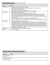
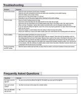
Troubleshooting
Problem Solution
The fan will not start. □ Check the main and branch circuit fuses or breakers.
□ Check to make sure the wall switch is in the on position, if applicable.
□ Check the line wire connections to the fan and switch wire connections in the switch housing.
□ Check the battery in the remote control.
□ Ensure you are in the normal range of 10-20 feet.
□ Ensure the dip switch settings are the same on the remote control and receiver.
□ Remember to turn off the power supply before checking the dip switches settings.
The fan is noisy. □ Ensure all motor housing screws are snug.
□ Ensure the screws that attach the fan blade bracket to the motor hub are tight.
□ Ensure the wire nut connections are not rattling against each other or the interior wall of the switch housing.
□ Allow a 24-hour “breaking in” period. Most noises associated with a new fan disappear during this time.
□ If you are using the ceiling fan light kit, ensure the screws securing the glassware are tight. Check that the light
bulbs are also secure.
□ Ensure the canopy is a short distance from the ceiling. It should not touch the ceiling.
□ Ensure your outlet box is secure and rubber isolator pads were used between the mounting plate and outlet box.
The fan wobbles. □ Check that all blade and blade arm screws are secure.
□ Most fan wobble problems are caused when blade levels are unequal. Check this level by selecting a point on
the ceiling above the tip of one of the blades. Measure from a point on the center of the blade to the point on the
ceiling. Rotate the fan until the next blade is positioned for measurement, and measure from the same point on
each blade to the ceiling. Repeat for each blade. Any measurement deviation should be within 1/8 in. Run the fan
for ten minutes. If the fan continues to wobble please contact Hampton Bay Customer Service and a balancing kit
will be sent to you at no charge.
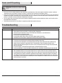
□ Because of the fan’s natural movement, some connections may become loose. Check the support connections, brackets, and blade
attachments twice a year. Make sure they are secure. It is not necessary to remove the fan from the ceiling.
□ Clean your fan periodically to help maintain its new appearance over the years. Do not use water when cleaning, as this could damage
the motor, or the wood, or possibly cause an electrical shock. Use only a soft brush or lint-free cloth to avoid scratching the nish. The
plating is sealed with a lacquer to minimize discoloration or tarnishing.
□ You can apply a light coat of furniture polish to the wood for additional protection and enhanced beauty. Cover small scratches with a
light application of shoe polish.
□ You do not need to oil your fan. The motor has permanently-lubricated sealed ball bearings.
WARNING: Make sure the power is off before cleaning
your fan.
Care and Cleaning

®
Questions, problems, missing parts? Before returning to the store,
call Hampton Bay Customer Service
8 a.m. - 6 p.m., EST, Monday-Friday
1-855-HD-HAMPTON
HAMPTONBAY.COM
Retain this manual for future use.
This equipment has been tested and found to comply with the limits for a Class B digital device, pursuant to Part 15 of the FCC Rules. These limits are designed
to provide reasonable protection against harmful interference in a residential installation. This equipment generates, uses and can radiate radio frequency energy
and, if not installed and used in accordance with the instructions, may cause harmful interference to radio communications. However, there is no guarantee that
interference will not occur in a particular installation. If this equipment does cause harmful interference to radio or television reception, which can be determined
by turning the equipment off and on, the user is encouraged to try to correct the interference by one or more of the following measures:
--Reorient or relocate the receiving antenna.
--Increase the separation between the equipment and receiver.
--Connect the equipment into an outlet on a circuit different from that to which the receiver is connected.
--Consult the dealer or an experienced radio/TV technician for help.
CAUTION:
Any changes or modications not expressly approved by the grantee of this device could void the user’s authority to operate the equipment.
This device complies with Part 15 of the FCC Rules. Operation is subject to the following two conditions: (1) This device may not cause harmful interference, and
(2) this device must accept any interference received, including interference that may cause undesired operation.
-
 1
1
-
 2
2
-
 3
3
-
 4
4
-
 5
5
-
 6
6
-
 7
7
-
 8
8
-
 9
9
-
 10
10
-
 11
11
-
 12
12
-
 13
13
-
 14
14
-
 15
15
-
 16
16
-
 17
17
-
 18
18


Hampton Bay 20010 Installation guide
- Category
- Household fans
- Type
- Installation guide
- This manual is also suitable for
Ask a question and I''ll find the answer in the document
Finding information in a document is now easier with AI
Related papers
-
 Hampton Bay 20037 Installation guide
-
 Hampton Bay 68044 User guide
-
Hampton Bay 22051 Installation guide
-
 Hampton Bay 20013 Installation guide
-
 Hampton Bay 20005 Installation guide
-
Hampton Bay 56056 User manual
-
 Hampton Bay 51827 Installation guide
-
Hampton Bay 59254 User guide
-
 Hampton Bay 51332 User guide
-
 Hampton Bay 20050 Installation guide


Other documents
-
RemotePro M802 Garage Remote Programming Operating instructions
-
Home Decorators Collection 51472 Troubleshooting guide
-
-
Home Decorators Collection 26666 User guide
-
Thermaltake SWAFAN EX12/14 ARGB Sync PC Cooling Fan TT Premium Edition User manual
-
Unbranded 8239205870 User guide
-
Triarch 32730/1 User manual
-
Trend TP30065 User manual
-
-
Progress Lighting P250102 Installation guide