
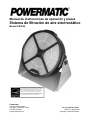
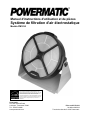
Operating Instructions and Parts Manual
Electrostatic Air Filtration System
Model PM1250
Powermatic
427 New Sanford Road
LaVergne, Tennessee 37086 Part No. M-1791331
Ph.: 800-274-6848 Edition 5 08/2019
www.powermatic.com Copyright © 2018 Powermatic
This product earned the ENERGY STAR
®
by meeting
strict energy efficiency guidelines set by the US EPA. US
EPA does not endorse any manufacturer claims of
healthier indoor air from the use of this product.
The energy efficiency of this ENERGY STAR
®
qualified
model is measured based on a ratio between the model’s
CADR for dust and the electrical energy it consumes, or
CADR/Watt.

2
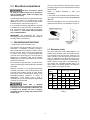
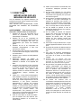
1.0 IMPORTANT SAFETY
INSTRUCTIONS
When using an electrical appliance, basic
precautions should always be followed, including
the following:
READ ALL INSTRUCTIONS BEFORE USING THIS
AIR FILTRATION UNIT.
WARNING – To reduce the risk of fire,
electric shock, or injury:
1. Read and understand the entire owner’s
manual before attempting assembly or
operation.
2. Read and understand the warnings posted on
the machine and in this manual. Failure to
comply with all of these warnings may cause
serious injury.
3. Replace warning labels if they become
obscured or removed.
4. Do not operate this machine while tired or under
the influence of drugs, alcohol or any
medication.
5. Make certain the machine is properly grounded.
6. Disconnect the filtration unit from the power
source (unplug) before servicing or changing
filters.
7. Keep guards and covers in place at all times
when the machine is in use. If removed for
maintenance purposes, use extreme caution
and replace the guards immediately after
service is complete.
8. Check damaged parts. Before further use of the
machine, a guard or other part that is damaged
should be carefully checked to determine that it
will operate properly and perform its intended
function. Check for alignment of moving parts,
binding of moving parts, breakage of parts,
mounting and any other conditions that may
affect its operation. A guard or other part that is
damaged should be properly repaired or
replaced.
9. Make your workshop child proof with padlocks,
master switches or by removing safety keys.
10. Use recommended accessories; improper
accessories may be hazardous.
11. Do not place this unit on an unstable surface, or
where there is a risk of tipping over. Serious
injury could occur if the unit tips over.
12. Do not use this air filtration unit with a damaged
cord or plug. If the unit is not working as it
should, has been dropped, damaged, left
outdoors, or dropped into water, return it to a
service center.
13. If ceiling mounted, bottom of filtration unit must
be at least 7 feet from the floor.
14. If ceiling mounted, mounts must be anchored to
building structure which will support the weight
of the air filtration unit. Never mount to surfaces
such as dry wall or false ceiling grids.
15. To reduce risk of electric shock, do not expose
filtration unit to water or rain.
16. Never duct a machine directly into the air
filtration unit.
17. To avoid a potentially dangerous situation, do
not use this equipment to filter volatile fumes or
smoke.
18. Do not use this unit in high humidity
environments. Doing so may cause electric
shock and/or decreased performance of the
unit.
19. Do not use this equipment to filter flammable
vapors. This air filtration unit is designed and
intended for the filtration of air borne dust only.
It is neither designed nor intended for any other
purpose whatsoever. If used for other purposes,
Powermatic disclaims any real or implied
warranty and holds itself harmless from any
injury that may result from that use.
20. This product complies with the maximum
allowable concentration of ozone of 0.050 parts
per million by volume (ppmv) in a 24-hour
period. The Health Canada Guideline 2010
recommends that the maximum exposure limit,
based on an averaging time of 8 hours, is 0.020
ppmv or less when tested in a sealed, controlled
room approximately 30 m
3
.
WARNING: This product can expose you to
chemicals including nickel which is known to the
State of California to cause cancer, and lead
which is known to the State of California to cause
cancer and birth defects or other reproductive
harm. For more information go to http://www.
p65warnings.ca.gov.

3
Familiarizeyourselfwiththefollowingsafetynoticesusedinthismanual:
This means that if precautions are not heeded, it may result in minor injury and/or possible
machine damage.
This means that if precautions are not heeded, it may result in serious or possibly fatal injury.
WARNING: Some dust, fumes and gases created by power sanding, sawing, grinding, drilling, welding and
other construction activities contain chemicals known to the State of California to cause cancer and birth
defects or other reproductive harm. Some examples of these chemicals are:
lead from lead based paint
crystalline silica from bricks, cement and other masonry products
arsenic and chromium from chemically treated lumber
Your risk of exposure varies, depending on how often you do this type of work. To reduce your exposure to
these chemicals, work in a well-ventilated area and work with approved safety equipment, such as dust masks
that are specifically designed to filter out microscopic particles. For more information go to
http://www.p65warnings.ca.gov/ and http://www. p65warnings.ca.gov/wood.

4
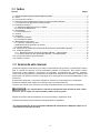
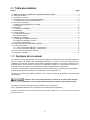
2.0 Table of contents
Section Page
1.0 IMPORTANT SAFETY INSTRUCTIONS ....................................................................................................... 2
2.0 Table of contents ............................................................................................................................................ 4
3.0 About this manual .......................................................................................................................................... 4
4.0 PM1250 Electrostatic AFS specifications ....................................................................................................... 5
4.1 PM1250 mounting hole pattern .................................................................................................................. 6
5.0 Electrical connections .................................................................................................................................... 7
5.1 GROUNDING INSTRUCTIONS ................................................................................................................. 7
5.2 Extension cords .......................................................................................................................................... 7
6.0 Unpacking ...................................................................................................................................................... 8
6.1 Shipping contents ....................................................................................................................................... 8
7.0 Assembly ........................................................................................................................................................ 8
8.0 Operation ....................................................................................................................................................... 8
8.1 Tilt Adjustment ............................................................................................................................................ 8
8.2 Basic procedure ......................................................................................................................................... 8
9.0 User-maintenance .......................................................................................................................................... 8
9.1 Filter cleaning and replacement ................................................................................................................. 8
9.2 Anion generator maintenance .................................................................................................................... 9
9.3 Additional servicing .................................................................................................................................... 9
10.0 Troubleshooting PM1250 Electrostatic AFS .............................................................................................. 11
11.0 Replacement parts ..................................................................................................................................... 12
11.1.1 PM1250 Electrostatic AFS – Parts List ............................................................................................... 12
11.1.2 PM1250 Electrostatic AFS – Exploded View ....................................................................................... 13
12.0 Electrical connections for PM1250 ............................................................................................................. 14
13.0 Warranty and Service ................................................................................................................................. 15
3.0 About this manual
This manual is provided by Powermatic covering the safe operation and maintenance procedures for the PM1250
Electrostatic Air Filtration System. This manual contains instructions on installation, safety precautions, general
operating procedures, maintenance instructions and parts breakdown. Your machine has been designed and
constructed to provide consistent, long-term operation if used in accordance with the instructions set forth in this
document.
If there are questions or comments, please contact your local supplier or Powermatic. Powermatic can also be
reached at our web site: www.powermatic.com.
Retain this manual for future reference. If the machine transfers ownership, the manual should accompany it.
Read and understand the entire contents of this manual before attempting assembly or
operation! Failure to comply may cause serious injury!
Register your product using the mail-in card provided, or register online:
http://www.powermatic.com/us/en/service-and-support/product-registration/
The PM1250 Electrostatic Air Filtration System is CARB certified to comply with the federal ozone
emissions limit.

5
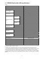
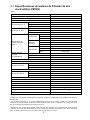
4.0 PM1250 Electrostatic AFS specifications
Table 1
Stock number
1791331
Model number
PM1250
Blower speeds 3
Timer settings (hours) 1, 2, 4, 8
Sound rating @ 1M
1
High speed 50.8 dBA ±10%
Medium speed 45.0 dBA ±10%
Low speed 41.3 dBA ±10%
Air flow with filter
1
High speed 1282 m
3
/h (754 cfm) ±10%
Medium speed
965 m
3
/h (567 cfm) ±10%
Low speed
751 m
3
/h (441 cfm) ±10%
CADR (Clean Air Delivery
Rate)
1,2,3
High speed
Smoke >450 cfm
Dust >400 cfm
Pollen >450 cfm
Medium speed
Smoke 354.5 cfm
Dust 363.8 cfm
Pollen 389.3 cfm
Low speed
Smoke 247.1 cfm
Dust 250.6 cfm
Pollen 261.9 cfm
Energy Efficiency Grade
(E=CADR/Power)
High speed >13.2
Medium speed 20.8
Low speed 23.2
Motor (input) 35W, DC 140V/165V
Electrical input required 120VAC, 60Hz, 15A
Current draw
1
High speed 29.7W ±10%
Medium speed 17.5W ±10%
Low speed 10.6W ±10%
Cord and plug SJT 18AWGx3C, 6 ft., 15A plug
Amperage draw
High speed 0.31 A
Medium speed 0.19 A
Low speed 0.13 A
Filter diameter 543 mm (21.3 in.)
Approximate filter life 3000 operating hours
Programmed cleaning alert (flashing red indicator) 1000 operating hours
Remote control batteries (2) AAA
Overall dimensions, WxHxD 27 x 25-5/8 x 15 in. (688 x 650 x 380 mm)
Shipping dimensions, LxWxH 29 x 28-1/2 x 14 in. (738 x 725 x 355 mm)
Net weight, approx. 38 lb. (17.3 kg)
Shipping weight, approx. 52 lb. (23.6 kg)
L = length, W = width, H = height, D = depth
1
Variable of ±10%, for general information only, not to be viewed as fixed parameters for inspection purposes.
2
Tests performed by independent third party in accordance with ANSI/AHAM AC-1-2015 entitled Association of Home
Appliance Manufacturers Method for Measuring Performance of Portable Household Electric Room Air Cleaners.
3
In accordance with AHAM’s 2/3 rule, these numbers are applicable to a room of up to 680 sq. ft. for airborne particles.
Powermatic always recommends using an appropriately sized dust collector in conjunction with our air filtration
systems.

6
The specifications in this manual were current at time of publication, but because of our policy of continuous
improvement, Powermatic reserves the right to change specifications at any time and without prior notice, without
incurring obligations.
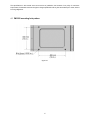
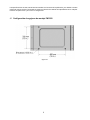
4.1 PM1250 mounting hole pattern
Figure 4-1

7
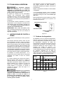
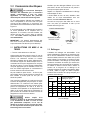
5.0 Electrical connections
Electrical connections should
be made by a qualified electrician in compliance
with all relevant codes. Failure to comply may
cause serious injury.
The PM1250 Electrostatic AFS is prewired for single
phase, 120V power. It is provided with a plug
designed for use on a circuit with a grounded outlet
that looks like the one pictured in Figure 5-1.
It is recommended that the PM1250 be connected
to a dedicated 15 amp circuit with circuit breaker or
fuse. If fuses are used, they should be time-delay
fuse marked “D”. Local codes take precedence
over recommendations.
IMPORTANT: This electrostatic unit must be
electrically grounded for proper operation, as well as
for safety reasons (see below).
5.1 GROUNDING INSTRUCTIONS
1. All Grounded, Cord-connected Tools:
This machine must be grounded. In the event of a
malfunction or breakdown, grounding provides a
path of least resistance for electric current to reduce
the risk of electric shock. This tool is equipped with
an electric cord having an equipment-grounding
conductor and a grounding plug. The plug must be
plugged into a matching outlet that is properly
installed and grounded in accordance with all local
codes and ordinances.
Do not modify the plug provided - if it will not fit the
outlet, have the proper outlet installed by a qualified
electrician.
Improper connection of the equipment-grounding
conductor can result in a risk of electric shock. The
conductor with insulation having an outer surface
that is green with or without yellow stripes is the
equipment-grounding conductor. If repair or
replacement of the electric cord or plug is
necessary, do not connect the equipment-grounding
conductor to a live terminal.
Check with a qualified
electrician or service personnel if the grounding
instructions are not completely understood, or if
in doubt as to whether the tool is properly
grounded. Failure to comply may cause serious
or fatal injury.
Use only 3-wire extension cords that have 3-prong
grounding plugs and 3-pole receptacles that accept
the tool's plug.
Repair or replace damaged or worn cord
immediately.
2. Grounded, cord-connected tools intended for use
on a supply circuit having a nominal rating less than
150 volts:
This tool is intended for use on a circuit that has an
outlet that looks like the one illustrated in Figure 5-
1.
Figure 5-1
5.2 Extension cords
The use of extension cords is discouraged. Try to
position machines within reach of the power source.
If an extension cord must be used, make sure it is
heavy enough to carry the current your product will
draw. An undersized cord will cause a drop in line
voltage resulting in loss of power and overheating.
Table 2 shows correct size to use depending on
cord length and nameplate ampere rating. If in
doubt, use the next heavier gauge. The smaller the
gauge number, the heavier the cord.
Ampere
Rating
Volts Total length of cord in feet
More
Than
Not
More
Than
120 25 50 100 150
AWG
00 06 18 16 16 14
06 10 18 16 14 12
10 12 16 16 14 12
12 16 14 12
Not
Recommended
Extension Cord Recommendations
Table 2

8
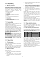
6.0 Unpacking
6.1 Shipping contents
Open shipping cartons and check that all parts are
intact. Report any damage or missing parts to your
distributor. Note that your unit may be provided with
extra fasteners. Read the instruction manual
thoroughly for assembly, alignment, and
maintenance instructions.
1 Air filtration unit
2 Side plates
1 Base plate
1 Remote control (batteries not included)
2 Knobs
6 Pan head screws with washers M5x10
4 Rubber pads
1 Cleaning brush
1 Operating instructions and parts manual
1 Product registration card
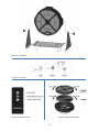
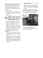
7.0 Assembly
Assemble base of unit with provided screws and
washers, as shown in Figure 8-1.
If filtration unit is to remain portable, press the four
rubber pads into the mounting holes.
The unit may also be fixed to a table, wall or ceiling,
using appropriate fasteners (not included) through
four holes in base. See Figure 4-1 for hole pattern.
3/8” diameter fasteners are recommended. NOTE:
First secure assembled base to structure, then
mount filtration unit with the two knobs.
Wall or ceiling structure must
be capable of supporting weight of air filtration
unit and absorbing any vibrations arising from
the unit. Appropriate fasteners must be used to
secure to structure. Failure to comply may
cause serious injury.
8.0 Operation
8.1 Tilt Adjustment
Loosen side knobs and tilt frame to any position.
Retighten both knobs.
For best results, when unit is ceiling-mounted
position front (filter side) downward; when unit is
table-mounted position front (filter side) vertically.
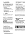
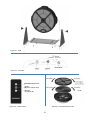
8.2 Basic procedure
Refer to Figure 8-2.
1. Plug in unit. On/off indicator light glows red for
standby mode.
2. Press Power button to start unit. Speed
indicator light glows green, and default speed is
selected.
3. Press and release Speed button until desired
speed indicator is green.
4. Press Timer button until desired timer indicator
is green. If Timer button is not pressed again for
3 seconds, the selected time indicator will flash
multiple times, then stay green.
5. Unit will count down from the corresponding
time, and will automatically shut off at time
expiration.
Example: 8H indicator stays green when timing
begins; switches to 4H indicator after four hours,
then to 2H indicator after another two hours, then to
1H, and finally unit will shut off and remain in
standby condition.
Note: If Timer function is not used, unit will continue
to operate until Power button is pressed.
All above functions can be operated remotely. See
Figure 8-3. The remote control uses radio
frequency, and thus is not limited to line-of-sight
operation.
9.0 User-maintenance
The batteries should be changed in the remote
control as needed, particularly if unit seems
unresponsive to remote operation.
9.1 Filter cleaning and replacement
The disposable filter is designed for approximately
3000 hours of life, dependent upon speed setting
and working environment. See Table 3.
Speed Operating
time
Approximate
filter life consumed
Low 1 hour 0.75 hours
Medium 1 hour 1 hour
High 1 hour 1.25 hours
Table 3
Filter life may be extended by occasional use of a
shop vacuum or compressed air to clean off the
dust. However, a dirty filter should be replaced as it
will diminish the efficiency of the unit.
Clean the filter after every 1000 hours of operation,
or more frequently if needed. The unit is
programmed to alert the user after 1000 hours; the
red indicator light will flash twice per second.
After 3000 hours of operation, the filter should be
discarded and replaced by a new one.

9
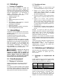
To remove filter:
1. When filter life reaches programmed time (1000
hours), red Reset indicator light will flash twice
per second.
2. Turn off unit.
CAUTION: The internal metal ring
carries an electrical charge during
operation. Turn off unit before
attempting to remove cover.
3. Rotate cover counterclockwise and remove it,
along with the prefilter. See Figure 8-4.
4. Hold the frame stationary, and rotate filter
counterclockwise to remove.
5. Clean dust from filter with vacuum or soft bristle
brush. Blow dust from recessed areas of filter
with a household air blower. Also clean out any
residual dust from inside the unit.
To install cleaned or replacement filter:
6. Center filter onto stator and turn it clockwise
(about 1/8 of a turn) until it fully engages – you
will feel a hard stop.
7. Install cover and rotate clockwise until it fully
engages. A lock/unlock graphic is molded into
left and right edges of the cover as a guide.
Note: A sensor prevents unit from starting if
cover is not installed properly.
8. Plug in unit. Red Reset indicator light will flash.
9. Press and hold Power button for 5 seconds until
red indicator light goes off. Filter life count is
now reset.
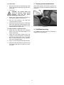
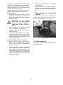
9.2 Anion generator maintenance
Remove dust regularly from the anion generator (i.e.
carbon brush) with the provided cleaning brush. See
Figure 9-1.
Figure 9-1
9.3 Additional servicing
Any additional servicing should be performed by
authorized service personnel.

1 0
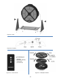
Figure 8-1: Assembly
Figure 8-2: Controls
Figure 8-3: Remote control Figure 8-4: Filter replacement

1 1
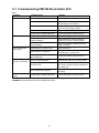
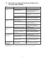
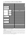
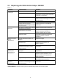
10.0 Troubleshooting PM1250 Electrostatic AFS
Table 4
Symptom Probable Cause Remedy*
Machine will not start.
No incoming power. Check plug connection.
Cover improperly installed. Reinstall cover. If properly installed, red light
will illuminate on control panel.
Low voltage. Request voltage check from power company
and correct low voltage condition.
Power cord damaged. Replace cord.
Control button or PCBA malfunction. Contact Powermatic customer service.
Excessive vibration.
Loose frame parts, knobs or fasteners. Inspect and tighten as needed.
Impeller imbalance.
Clean impeller (do not use solvents). If
imbalance still occurs, replace impeller.
Motor imbalance.
Have motor tested by qualified personnel;
replace if needed.
Unit not responding to
remote control.
Weak batteries in remote control. Replace batteries.
Radio frequency interference.
Identify sources of interference and
eliminate them, or relocate unit.
Remote control or machine control
panel malfunction.
Contact Powermatic customer service.
Unit not working
efficiently; not cleaning
air.
Filter not installed properly. Reinstall filter; make sure it is fully rotated.
Blocked air flow.
Inspect filter; replace if dirty. Vacuum or
blow out the pre-filter and any residual dust
from inside unit.
Unit not electrically grounded.
Check power source; make sure grounding
is working.
Controls on unit not
working.
Control button or PCBA malfunction. Contact Powermatic customer service.
* WARNING: Some remedies may require a qualified electrician.

1 2
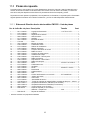
11.0 Replacement parts
To order parts or reach our service department, call 1-800-274-6848 Monday through Friday, 8:00 a.m. to 5:00
p.m. CST. Having the Model Number and Serial Number of your machine available when you call will allow us to
serve you quickly and accurately.
Non-proprietary parts, such as fasteners, can be found at local hardware stores, or may be ordered from
Powermatic.
Some parts are shown for reference only, and may not be available individually.
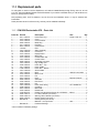
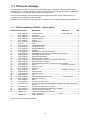
11.1.1 PM1250 Electrostatic AFS – Parts List
Index No Part No Description Size Qty
1 ................ 2211-J1000-01 .......... Powermatic Logo ..................................................... W100 x H36 mm ........... 1
2 ................ 2101-J1000-01 .......... Cover ....................................................................... ...................................... 1
3 ................ 2112-J1000-01 .......... Cover Fastener ........................................................ ...................................... 4
4 ................ 2203-J1000-01 .......... Metal Ring ............................................................... ...................................... 1
5 ................ 2111-J1000-01 .......... Pre-Filter .................................................................. ...................................... 1
6 ................ 2501-J1000-01 .......... Carbon Brush .......................................................... ...................................... 1
7 ................ 1791332 .................... Filter ......................................................................... ...................................... 1
8 ................ 7201-J1000-02 .......... Stator Assembly....................................................... ...................................... 1
9 ................ 2109-J1000-01 .......... Cord Cover .............................................................. ...................................... 2
10 .............. 2115-J1000-01 .......... Display Board .......................................................... ...................................... 1
11 .............. 2102-J1000-01 .......... Mid-Frame ............................................................... ...................................... 1
12 .............. 2114-J1000-01 .......... Control Button Set ................................................... ...................................... 1
13 .............. 1812-J1000-01 .......... Control PCBA .......................................................... ...................................... 1
14 .............. 2205-J1000-01 .......... Grounding Connector .............................................. ...................................... 1
15 .............. 7201-J1000-01 .......... High Voltage Unit ..................................................... ...................................... 1
16 .............. 2105-J1000-01 .......... Power Box – Top ..................................................... ...................................... 1
17 .............. 1811-J1000-01 .......... Power PCBA ............................................................ ...................................... 1
18 .............. 2106-J1000-01 .......... Power Box – Bottom ................................................ ...................................... 1
19 .............. 1813-J1000-02 .......... Switch PCBA ........................................................... ...................................... 1
20 .............. 1821-J1000-01 .......... Motor ....................................................................... 35W DC 140V/165V ..... 1
21 .............. 2110-J1000-01 .......... Motor Cover ............................................................. ...................................... 1
22 .............. 2107-J1000-01 .......... Fan .......................................................................... ...................................... 1
23 .............. 2401-J1000-01 .......... Knob ........................................................................ M10x25 D=60mm ......... 2
24 .............. 2202-J1000-01 .......... Side Plate ................................................................ ...................................... 2
25 .............. 2103-J1000-01 .......... Rear Cover .............................................................. ...................................... 1
26 .............. 2204-J1000-01 .......... Net ........................................................................... ...................................... 1
27 .............. 1801-J1000-02 .......... Power Cord w/Plug .................................................. SJT 18AWGx3C ........... 1
28 .............. 2108-J1000-01 .......... Cord Grip ................................................................. ...................................... 1
29 .............. 2201-J1000-01 .......... Base Plate ............................................................... ...................................... 1
30 .............. 2118-J1000-01 .......... Rubber Pad * ........................................................... ...................................... 4
31 .............. 3130-05010-01 .......... Phillips Pan Hd Machine Screw w/Lock Washer * ... M5x10 ........................... 6
33 .............. 4230-J1000-11 .......... I.D. Label, PM1250 (not shown) .............................. ...................................... 1
34 .............. 4230-J1000-13 .......... Warning Label, PM1250 (not shown) ...................... ...................................... 1
35 .............. 2502-J1000-01 .......... Remote Control (not shown) .................................... ..................
.................... 1
36 .............. PM1250-36 ................ Cleaning Brush (not shown) .................................... ...................................... 1
.................. .................................. Batteries – local purchase ....................................... AAA ............................... 2
.................. PM1250-HP ............... Hardware Package .................................................. ........................................
* items included in hardware package

1 3
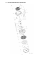
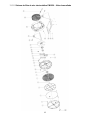
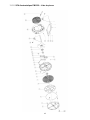
11.1.2 PM1250 Electrostatic AFS – Exploded View

1 4
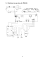
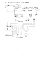
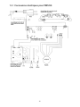
12.0 Electrical connections for PM1250

1 5
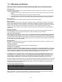
13.0 Warranty and Service
Powermatic
®
warrants every product it sells against manufacturers’ defects. If one of our tools needs service or
repair, please contact Technical Service by calling 1-800-274-6846, 8AM to 5PM CST, Monday through Friday.
Warranty Period
The general warranty lasts for the time period specified in the literature included with your product or on the official
Powermatic branded website.
Powermatic products carry a limited warranty which varies in duration based upon the product. (See chart
below)
Accessories carry a limited warranty of one year from the date of receipt.
Consumable items are defined as expendable parts or accessories expected to become inoperable within a
reasonable amount of use and are covered by a 90 day limited warranty against manufacturer’s defects.
Who is Covered
This warranty covers only the initial purchaser of the product from the date of delivery.
What is Covered
This warranty covers any defects in workmanship or materials subject to the limitations stated below. This warranty
does not cover failures due directly or indirectly to misuse, abuse, negligence or accidents, normal wear-and-tear,
improper repair, alterations or lack of maintenance. Powermatic woodworking machinery is designed to be used with
Wood. Use of these machines in the processing of metal, plastics, or other materials outside recommended
guidelines may void the warranty. The exceptions are acrylics and other natural items that are made specifically for
wood turning.
Warranty Limitations
Woodworking products with a Five Year Warranty that are used for commercial or industrial purposes default to a
Two Year Warranty. Please contact Technical Service at 1-800-274-6846 for further clarification.
How to Get Technical Support
Please contact Technical Service by calling 1-800-274-6846. Please note that you will be asked to provide proof
of initial purchase when calling. If a product requires further inspection, the Technical Service representative will
explain and assist with any additional action needed. Powermatic has Authorized Service Centers located throughout
the United States. For the name of an Authorized Service Center in your area call 1-800-274-6846 or use the Service
Center Locator on the Powermatic website.
More Information
Powermatic is constantly adding new products. For complete, up-to-date product information, check with your local
distributor or visit the Powermatic website.
How State Law Applies
This warranty gives you specific legal rights, subject to applicable state law.
Limitations on This Warranty
POWERMATIC LIMITS ALL IMPLIED WARRANTIES TO THE PERIOD OF THE LIMITED WARRANTY FOR EACH
PRODUCT. EXCEPT AS STATED HEREIN, ANY IMPLIED WARRANTIES OF MERCHANTABILITY AND FITNESS
FOR A PARTICULAR PURPOSE ARE EXCLUDED. SOME STATES DO NOT ALLOW LIMITATIONS ON HOW
LONG AN IMPLIED WARRANTY LASTS, SO THE ABOVE LIMITATION MAY NOT APPLY TO YOU.
POWERMATIC SHALL IN NO EVENT BE LIABLE FOR DEATH, INJURIES TO PERSONS OR PROPERTY, OR
FOR INCIDENTAL, CONTINGENT, SPECIAL, OR CONSEQUENTIAL DAMAGES ARISING FROM THE USE OF
OUR PRODUCTS. SOME STATES DO NOT ALLOW THE EXCLUSION OR LIMITATION OF INCIDENTAL OR
CONSEQUENTIAL DAMAGES, SO THE ABOVE LIMITATION OR EXCLUSION MAY NOT APPLY TO YOU.
Powermatic sells through distributors only. The specifications listed in Powermatic printed materials and on the official
Powermatic website are given as general information and are not binding. Powermatic reserves the right to effect at
any time, without prior notice, those alterations to parts, fittings, and accessory equipment which they may deem
necessary for any reason whatsoever.
Product Listing with Warranty Period
90 Days – Parts; Consumable items
1 Year – Motors, Machine Accessories
2 Year – Woodworking Machinery used for industrial or commercial purposes
5 Year – Woodworking Machinery
NOTE: Powermatic is a division of JPW Industries, Inc. References in this document to Powermatic also apply to
JPW Industries, Inc., or any of its successors in interest to the Powermatic brand.

1 6
427 New Sanford Road
LaVergne, Tennessee 37086
Phone: 800-274-6848
www.powermatic.com
Page is loading ...
Page is loading ...
Page is loading ...
Page is loading ...
Page is loading ...
Page is loading ...
Page is loading ...
Page is loading ...
Page is loading ...
Page is loading ...
Page is loading ...
Page is loading ...
Page is loading ...
Page is loading ...
Page is loading ...

427 New Sanford Road LaVergne,
Tennessee 37086
Teléfono: 800-274-6848
www.powermatic.com
Page is loading ...
Page is loading ...
Page is loading ...
Page is loading ...
Page is loading ...
Page is loading ...
Page is loading ...
Page is loading ...
Page is loading ...
Page is loading ...
Page is loading ...
Page is loading ...
Page is loading ...
Page is loading ...
Page is loading ...

427 New Sanford Road
LaVergne, Tennessee 37086
Téléphone : 800-274-6848
www.powermatic.com
-
 1
1
-
 2
2
-
 3
3
-
 4
4
-
 5
5
-
 6
6
-
 7
7
-
 8
8
-
 9
9
-
 10
10
-
 11
11
-
 12
12
-
 13
13
-
 14
14
-
 15
15
-
 16
16
-
 17
17
-
 18
18
-
 19
19
-
 20
20
-
 21
21
-
 22
22
-
 23
23
-
 24
24
-
 25
25
-
 26
26
-
 27
27
-
 28
28
-
 29
29
-
 30
30
-
 31
31
-
 32
32
-
 33
33
-
 34
34
-
 35
35
-
 36
36
-
 37
37
-
 38
38
-
 39
39
-
 40
40
-
 41
41
-
 42
42
-
 43
43
-
 44
44
-
 45
45
-
 46
46
-
 47
47
-
 48
48


Powermatic PM1250 Micro Dust AFS User manual
- Type
- User manual
- This manual is also suitable for
Ask a question and I''ll find the answer in the document
Finding information in a document is now easier with AI
in other languages
Related papers
-
Powermatic 1791332 User manual
-
-
-
-
-
-
-
-
-
Other documents
-
Jet Tools AFS-400 User manual
-
-
JET 728100 Owner's manual
-
Heaven Fresh HF 380 User manual
-
-
Manitowoc J User manual
-
Manitowoc Ice J Model Technicians Handbook User manual
-
Greenheck 472846 PVe Operating instructions
-
-
Manitowoc Ice J Model Installation guide