Page is loading ...

www. eldcontrols.com
Please retain these instructions after installation.
This device MUST be installed by a quali ed agency in accordance with the manufacturer's installation instructions. The de nition of
a quali ed agency is: any individual, rm, corporation or company which either in person or through a representative is engaged
in, and is responsible for, the installation and operation of HVAC appliances, who is experienced in such work, familiar with all the
precautions required, and has complied with all the requirements of the authority having jurisdiction.
READ THESE INSTRUCTIONS CAREFULLY AND COMPLETELY BEFORE PROCEEDING WITH THE INSTALLATION.
Installation Date:
Installed By: Phone:
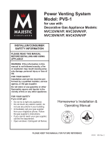
SIDEWALL VENT HOOD
Model: SWH-4"-8"
SWH-4 Model SWH-5-8 Models
P/N 46096300 Rev D 02/20

page 2 of 4
This device should be installed in accordance with the National Fuel Gas Code ANSI Z223.1 (See
Requirements Below) and any local codes which are applicable. All individual or multiple appliance vents
must enter the vent system on the inlet side of the venter.
1. The exit terminals of mechanical draft systems shall be not less than 7' above grade when located
adjacent to public walkways.
2. A venting system shall terminate at least 3' above any forced air inlet located within 10'.
3. The venting system of other than a direct vent appliance shall terminate at least 4' below, 4' horizontally
from, or 1' above any door, window, or gravity air inlet into any building.
4. The vent termination of a direct vent appliance with an input of 50,000 BTU per hour or less shall be
located at least 9" from any opening through which vent gases could enter a building, and such an
appliance with an input over 50,000 BTU per hour shall require a 12" vent termination clearance. The
bottom of the vent terminal and any air intake shall be located at least 12" above grade.
5. Power venter should be located as close as possible to the outside wall. Forced draft systems and
all portions of induced draft systems under positive pressure during operation shall be designed and
installed so as to prevent leakage of vent gases into building.
6. The vent termination point shall not be installed closer than 3' from an inside corner of an L-shaped
structure, or not less than 12" above grade.
7. For proper ventilation and for reduction of combustion hazards, Class B type vent pipe is recommended
for gas appliances and Class L type vent pipe for oil appliances.
P/N 46096300 Rev D 02/20

page 3 of 4
MAINTENANCE
The vent system should be inspected regularly at 3-month intervals.
1. Screened opening of vent hood should be free from foreign material and cleaned if necessary.
2. Check all vent system connections for leakage and re-seal where necessary.
Please refer to the owners manual for complete system installation and safety instructions, multiple venting
systems, trouble shooting hints and maintenance instructions.
INSTALLATION
1. Use inside wall end plate as a template to mark hole location. Cut hole
1
⁄2" larger than marked hole to
facilitate easy installation.
2. Install vent hood through opening from outside. Fasten the vent hood to the outside wall with appropriate
type mounting screws.
3. Fasten wall end plate to the inside wall with appropriate type mounting screws.
4. Install a properly sized vent pipe section into inner pipe of the vent hood. Seal the connection and all
other vent pipe joints on the pressure side of the Power Venter with a high temperature silicone adhesive
sealant or equivalent. Fasten vent pipe connection with three sheet metal screws or with other appropriate
type mounting screws.
INSTALLATION SAFETY INSTRUCTIONS
CAUTION: This device must be installed by a quali ed installer in accordance with the manufacturer's
installation instructions and applicable codes.
1. Plan the vent system layout to avoid the possibility of accidental contact with concealed wiring or
plumbing inside of wall.
2. Single wall vent pipe may be used to join an appliance to the power venter, but if proper clearance
cannot be maintained from combustible material or when passing through a side wall, Class B type vent
pipe should be used for gas appliances and Class L type vent pipe for oil appliances.
3. The power venter should be installed as close to the termination of the vent system as possible to reduce
e ects of wind, and outlet blockage, and to guard against ue gas leakage. Vent pipe must be sealed on
the positive pressure side of the venter. Pipe joints and seams should be sealed with a high temperature
silicone adhesive sealant or equivalent. Test vent connections for leaks by using a soap solution as
recommended by the National Fuel Gas Code: ANSI Z223.1, Section 4.11.
4. Vent hood inlet diameter should never be smaller than the installed vent pipe.
P/N 46096300 Rev D 02/20

Phone: 252.522.3031 • Fax: 252.522.0214
www.fieldcontrols.com
© Field Controls, LLC P/N 46096300 Rev D 02/20
This manual may be downloaded and printed from the Field Controls website (www. eldcontrols.com)
This manual may be downloaded and printed from the Field Controls website (www. eldcontrols.com)
WARRANTY
WARRANTY
For warranty information about this or any Field Controls product, visit:
For warranty information about this or any Field Controls product, visit:
www. eldcontrols.com/ventCool
www. eldcontrols.com/ventCool
Field Controls Technical Support
Field Controls Technical Support
1.800.742.8368
1.800.742.8368
eldtec@ eldcontrols.com
eldtec@ eldcontrols.com
/