Page is loading ...

MR03-B3P
Microwave Motion Sensor
Manual
www.ltech-led.com

01
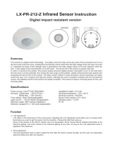
System Diagram
Wi-Fi/4G/5G
Ethernet
Wi-Fi
Super Panel 6S
Phone user 1
Phone user... Scene Timing Automation
CLOUD
Router Amazon Echo
Bluetooth 4.2
Google
Bluetooth speaker
Mesh
LAN
Wireless
switch
Home appliances & accessories
Bluetooth
remote
Wireless module
Home appliance
module
More
...
Intelligent Lighting
Bluetooth
mesh
HVAC manage-
ment module
Curtain
motor
MusicplayerRelay
Phone user...
Bluetooth mesh
Constant Current
SE-12 series
SE-20series
SE-30series
SE-40series
LM-36 series
LM-150series
LM-240 series
Constant Voltage
LM-75series
Premium series
Smart Switch
Creativity series
Activated series
...
Sensor
Motion sensor
Microwave motion sensor
...
Wireless + Wired
Wireless module
(DMX/0-10V)
Wireless module
(DMX/DALI/0-10V)
Wireless module
(DALI)
Wireless module
(Triac)

02
Product Features
Apply motion sensing technology to detect human motions in a detection area.
Running on the Bluetooth 5.0 SIG Mesh system, the sensor outputs DALI or 0-10V dimming
signal and support wired and wireless control.
Work with a smart gateway to trigger cloud scenes or advanced lighting linkage, making
application scenarios enriched.
Support execution of local scenes without a gateway or the Internet needed, which run faster
and stably.
Support sensor grouping function to easily control multiple lights from one location.
Control lights intelligently and accurately with high sensitivity and high anti-interference capacity.
Turn relay turns on/off and support 2-step dimming and 3-step dimming, making sensors ideal
for corridors, stairways, offices, etc.
Use zero-crossing detection technology so current flowing through the relay contacts is close
to zero at the moment when the relay is turned on or off, effectively improving the lifetime of
a relay.
Ceiling mounted sensors fit well for homes, offices, shopping malls and more to easily achieve
smart lighting control.
Easily set parameters via dip switches, the infrared remote, or via the mobile APP.

03
Technical Specs
Othors
Input Input voltage
Output
Operating mode
Load type
Load capacity
Transmit power
Stand-by power consumption
Operating frequency
Parameters
Sensitivity
Hold time
Daylight threshold
Environment Working temperature
Storage temperature
Terminal specs
Mounting type
Hole size for installation
Net weight
Dimensions
Package size
Bluetooth 5.0 SIG Mesh , DALI dimming(with built-in
DALI bus power supply), 0-10V dimming, ON/OFF
120-277Vac, 50/60Hz
Capacitive/resistive load
≤400VA(Capacitive load), ≤800W(Resistive load)
≤1.5W
0.3mW
-20°C~55°C
-40°C~80°C
5.8GHz
100%,50%
5S, 30S, 1min, 10min
2lux, 10lux, 50lux, Disable
Wire diameter: 0.5-2.5mm /22-14AWG
Strip length: 5-6mm
2
Ceiling mount
φ70mm-φ80mm (recommendφ75mm)
103×103×105mm(LxWxH)
149g
Φ90×85.6mm
DALI output Max. 70mA
(APP/Remote offers sensibility options: 100%, 75%, 50%, 25%)
10S, 30S, 10min,
50%, 30%, 10%, Disable
Stand-by period
Stand-by dimming
Inrush current test 2KV
IP20
IPgrade

04
Signal selection
L N N L1 / /
L N N L1 / /
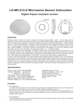
Product Size
85.6
69.0
58.4
56.1
Φ90
Unit: mm
Product Structure
DALI/0-10V signal
Live line input
Null line input
Live line output Null line output
Daylight threshold
Reset button
Long press for 6s
to reset device
Hold time
Sensitivity
Stand-by period
Stand-by dimming

L N N L1 / /
L N N L1 / /
DALIdriver
N
L
N
L
DA
DA
DALI signal
120-277Vac
05
Note: When a smart device is connected to the port of the relay and the relay turns off, the smart device
won’t respond to any control commands since it has no power supply.
Wiring Diagram
Bluetooth driver connection
L N N L1 / /
L N N L1 / /
Bluetooth
LED driver
N
L
N
L
Bluetooth 5.0
SIG Mesh
120-277Vac
DALI driver connection

06
The built-in relay allows max. 8A of resistive load or inrush current of less than 65A.
0-10V driver connection
L N N L1 / /
L N N L1 / /
N
L
DIM+
0-10Vdriver
0-10V signal
N
L 120-277Vac
Traditional lamp connection
L N N L1 / /
L N N L1 / /
Traditional lamp
N
L 120-277Vac

07
Installation Steps
75mm
1. Drill a 75mm hole (2.95 inches) in a desired
position of the ceiling.
2. Use a small flat head screwdriver to
pry the cover off.
3. Connect the wires.4. Secure the small board to fix the wires
and close the cover.
5. Pull the spring clip upward while insert
the sensor into the predrilled hole.
6. Please make sure you can mount it flat
on the ceiling.

08
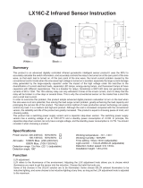
Range Diagrams for Big Motion Detection
Sensor coverage chart
(forsensormountedincenterofroom)
Ceiling
height
Max.room
dimensionsfor
completecoverage
Radiusof
coverage
atfloor
2.5m 6.8m
3.0m
4.0m
7.2m
8.0m
9.6×9.6m
10.2×10.2m
11.3×11.3m
Note: Multiplesensorscanbeaddedforextendedcoverage-refertoproductspecificationsubmittalsof
receivingdevicetodeterminesystemlimits
Sensor coveragewith an 4.0m ceiling
Ceiling
Floor
4.0m
Ceilingheight
8.0m
Radiusofcoverageatfloorwhen
mountedonan4.0mceiling
0m4.0m8.0m12m
Radiusofcoverageatfloor
Sensor
Occupant
11.3×11.3m
Maximumroomdimensions for
complete coverage when mounted
on an 4.0m ceiling
4.0m 8.0m 12m

09
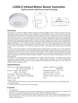
Range Diagrams for Minute Motion Detection
0m1.5m3.0m4.5m 1.5m 3.0m 4.5m
Sensor coverage chart
(forsensormountedincenterofroom)
Ceiling
height
Max.room
dimensionsfor
completecoverage
Radiusof
coverage
atfloor
2.5m 2.0m
3.0m
4.0m
2.4m
3.0m
2.8×2.8m
3.4×3.4m
4.2×4.2m
Note: Multiplesensorscanbeaddedforextendedcoverage-refertoproductspecificationsubmittalsof
receivingdevicetodeterminesystemlimits
Sensor coveragewith an 4.0m ceiling
Ceiling
Floor
4.0m
Ceilingheight
3.0m
Radiusofcoverageatfloorwhen
mountedonan4.0mceiling
Radiusofcoverageatfloor
Sensor
Occupant
4.2×4.2m
Maximumroomdimensions for
complete coverage when mounted
on an 4.0m ceiling

10
1108 9
Dip Switch Settings
Sensibility
100%
50%
12 3
5s
30s
10min
1min
4 5 6 7 8 9 10
10s
30s
∞
10min
50%
30%
10%
Disable Disable
50Lux
10Lux
2Lux
0-10V
DALI
ON
Dip switch 1:Sensibility. Sensor sensitivity can be selected by placing the dip switch in the on or
off position to match different detection range.
Dip switch 2-3: Hold time. Lamp remains 100% illuminated over this time period after no motion
is detected.
Dip switch 4-5: Stand-by period. Lamp remains at a low light level over this time period before it
completely switches off in the long absence of people. When the stand-by period
is set to “ ” mode, the low light level is maintained until a motion is detected.
Dip switch 6-7: Stand-by dimming. This low light level is used in periods of absence for enhanced
comfort and safety.
Dip switch 8-9: Daylight threshold. The sensor can be set up to work based on the ambient light
level. When the ambient light is 2lux, 10lux or even reaches 25lux, 50lux, the
sensor will trigger the light fixture to turn on. “Disable” mode will disable the
ambient light sensing feature, which means the light fixture will be triggered to
turn on once a motion is detected regardless of the ambient light level.
Dip switch 10: Signal. 0-10V or DALI signaloption.
Hold time Stand-by period Stand-by dimming Daylight threshold Signal
Sensibility Hold time Stand-by period Stand-by dimming Daylight threshold Signal
674 5
23

Auto-on and auto-off (Set stand-by dimming to “Disable”)
1 2
3 3
Functions
1With sufficient ambient light (whenlight
sensing feature enabled), the light fixture
won’t switch on even when a motion is
detected.
2With insufficient ambient light (whenlight
sensing feature enabled), the light fixture
will switch on when a motion is detected.
3When the sensor does not detect a motion,
time will start counting down according to
the preset hold time. After the hold time
ends, the light fixture will automatically
switch off. If a motion is detected during
the hold time, time will start counting
down again after no motion is detected.
2-step dimming function (Set stand-by period to ∞)
1 2
3 3
1When no motion is detected, the light fix-
ture will remain at a low light level (stand-
by dimming level).
2When a motion is detected, the light fixture
will be 100% illuminated.
3When the sensor does not detect a motion,
time will start counting down according to
the preset hold time. After the hold time
ends, light will be adjusted back to a low
level during the stand-by period. If a motion
is detected during the hold time, time will
start counting down again after no motion
is detected.
11

12
Sensor Working Principle Diagram
1 2
3 3
3-step dimming function
1With sufficient ambient light (when light
sensing feature enabled) , the light fixture
won’t switch on when a motion is detected.
2With insufficient ambient light (when light
sensing featureenabled) , the light fixture
will switch on automatically when a motion
is detected.
3When the sensor does not detect a motion,
time will start counting down according to
the preset hold time. After the hold time
ends, light will be adjusted back to a low
level during the stand-by period. If no mo-
tion is detected after the stand-by period
ends, the light fixture will switch off auto-
matically.
Auto-on and auto-off
Ambient light Sufficient
Insufficient
Human Occupancy
Vacancy
Light fixture 100% illuminated
OFF
Hold
time
period
Hold
time
period

13
2-step dimming function (For example, set brightness at 100% when human are detected, and
set stand-by dimming at 50%)
Ambient light Sufficient
Insufficient
Human Occupancy
Vacancy
Light fixture 100% illuminated
Stand-by period
50% illuminated
Hold
time
period
Hold
time
period
3-step dimming function (For example, set brightness at 100% when human are detected, and
set stand-by dimming at 50%)
Ambient light Sufficient
Insufficient
Human Occupancy
Vacancy
Light fixture 100% illuminated
OFF
50% illuminated
Hold
time
period
Stand-by
period Stand-by
period
Hold
time
period

14
Group Control Function
When no motion is detected,
all lights will turn off.
1
When the ambient light is
insufficient and a motion in
any direction is detected, all
lights will turn on.
2
After the delay time ends
and no motion is detected,
all lights will be adjusted to
a low brig htne ss level
simultaneously.
3
After the stand-by time ends
and no motion is detected,
all lights will turn off
simultaneously.
4
When multiple sensors are installed in a certain area and are grouped together, all lights will turn
on/off simultaneously once any sensor detects human motions. This function can expand the
sensor coverage area and effectively reduce both false detections and missed detections
(Please refer to Page 17 in this manual for more details).
sensor sensor sensor
sensor sensor sensor
sensor sensor sensor
sensor sensor sensor

15
Recommended Applications
2. Wired lighting control with DALI/0-10V signal output makes different application scenarios enriched.
+
Phone
+
Microwave motion sensor DALI/0-10V driver Lamp
3. Work with a smart gateway to realize visual control and automated linkage.
+
IR remote
+
Microwave motion sensor LED driver Lamp
+ + + + ...
4. Link the Super Panel 6S with App to achieve cloud scenes and automation.
Phone Microwave motion sensorSuper Panel 6S Home appliance module Curtain
1. Work with a Bluetooth LED driver to wirelessly control the lamp.
+
Phone
+
Microwave motion sensor Bluetooth LED driver Lamp

16
App Operating Instructions
1. Register an account
Scan the QR code below with you mobile phone and follow the prompts to complete the app in-
stallation. Then open the App and log in or register an account.
2. Connect to the network
Create a home if you are a new App user. Long press the reset button of the sensor for more than
6s to trigger network connection until the buzzer beeps. Click【+】icon in the upper right corner
of“Room” interface to access “Add device” page. Pick【Microwavemotion sensor】and follow the
on-screen prompts to add the device.

17
3. Control interface settings
In【Room】interface, click the microwave motion sensor you have added to access its control
interface. Tap【 】icon to enable/disable the sensor, 【 】icon to set the daylight threshold
and【 】icon set the detection sensibility.
In “Sensor settings”, click【When motions are detected, the following will be triggered】to select
a trigger action such as a light (ON/OFF), a smart light (with a 0-10V/DALI driver), a smart device,
a local scene or no action performed; Click【When no motion is detected, action still performs
within】to set the hold time; Click【Light remains at a low light level after action stop performing】
to set the stand-by period and device status in this period; Click【No motion is detected after the
stand-by period ends】to set the device status after no motion detected (only when you select a
smart device or a local scene as a trigger action can you change the device status after no motion
detected; when you select a light (ON/OFF) or a smart light (with a 0-10V/DALI driver) as a trigger
action, the default state for the light is “OFF” after no motion detected.
Microwave motion sensor Microwave motion sensor
Add automation Add automation

18
5.Sensor group
Click the【+】icon at the top-right corner of the "Room" interface and pick【Group-Sensor group】
from the device list. Create a group and set the group name and the room it belongs to. Then click
the devices you want to group together. Once the group is created successfully, the device data of
the group will be synchronized to the group to achieve synchronous control.
4.Power on relay always
In “Sensor settings”, when you click【When motions are detected, the following will be triggered】
to select a trigger action such as a smart device, a local scene or no action performed, go to
“Settings” page by clicking【 】at the top-right corner where “Power on relay always” button
is displayed. When the button is turned on, the relay will remain powered and won’t turn off in
the automation/scene despite the setting. When it is turned off, the relay status will change
according to the microwave detection situation. The relay will turn on when motions are detected
and will turn off when no motion is detected. You also can go to automation/scene setting to set
the executing action as the relay turning on/off.

19
Bind a local scene
Create a local scene
6.Local scene
Bind a local scene: In the control interface, click【Sensor settings】—【Local scene】to pick a
scene and save it. When the preset condition is triggered, the bound local scene can be performed.
Create a local scene: Switch to the "Intelligence" interface and click 【+】icon at the top-right
corner to create a local scene. After you set the executing action, the local linkage between
Bluetooth devices can be achieved.
/