Page is loading ...

IT
EN
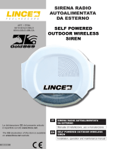
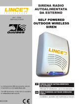
SIRENA LED AUTOALIMENTATA
DA ESTERNO
Manuale di installazione, uso e manutenzione
Installation, operation and maintenance manual
SELF POWERED OUTDOOR LED SIREN
ART. / ITEM:
1826OBLO/E
OBLO’/E
MADE IN ITALY
La dichiarazione CE del presente articolo
è reperibile sul sito www.lince.net.
The CE declaration of this item is available
on www.lince.net website.

2
LINCE ITALIA S.p.A.
- Istruzioni originali -
Le informazioni riportate in questo manuale sono state compilate con cura, tuttavia
LINCE ITALIA S.p.A. non può essere ritenuta responsabile per eventuali errori e/o
omissioni. LINCE ITALIA S.p.A. si riserva il diritto di apportare in ogni momento
e senza preavviso, miglioramenti e/o modiche ai prodotti descritti nel presente
manuale. Consultare il sito www.lince.net per le condizioni di assistenza e garanzia.
LINCE ITALIA S.p.A. pone particolare attenzione al rispetto dell’ambiente. Tutti i
prodotti ed i processi produttivi sono progettati con criteri di eco-compatibilità.
Il presente articolo è stato prodotto in Italia.
• L’aziendahaunsistemadigestionedellaqualitàcerticatosecondola
norma ISO 9001:2008 (n° 4796 - A)
• L’aziendahaunsistemadigestioneambientalecerticatosecondola
norma ISO 14001:2004 (n° 4796 - E)
• L’azienda ha un sistema di gestione della salute e sicurezza sul lavoro
certicatosecondolanormaISO45001:2018(n°4796-I)
1. INTRODUZIONE
Il manuale descrive le modalità di installazione della sirena
autoalimentata 1826OBLO/E. La sirena è il principale dispositivo
di segnalazione a cui deve essere dato un alto grado di sicurezza
e di afdabilità nel tempo. La sirena 1826OBLO/E è conforme
alla normativa CEI EN50131-4 Grado 2, Classe IV. L’apertura
del coperchio e lo strappo dal muro sono protetti dalla presenza
di 1 microswitch mentre il funzionamento a sicurezza intrinseca
(allarme per mancanza di positivo o di negativo) protegge contro
il taglio dei cavi. La sirena dispone di un contatto normalmente
chiuso (NC) per il collegamento con la linea antisabotaggio delle
centrali antifurto.
1.1 CARATTERISTICHE GENERALI
• Contenitore in policarbonato.
• Selezione tono sirena tramite jumper (JP4).
• Flash LED per segnalazione ottica.
• LED per segnalazione stato impianto.
• Protezione contro taglio li.
• Protezione contro la rimozione del coperchio.
• Protezione contro lo strappo dal muro.
• Durata limitata della segnalazione acustica.
• Durata illimitata della segnalazione ottica.
• Controllo batteria ogni 5 minuti.
• Controllo speaker.
• Circuito antisabotaggio incorporato.
• Scheda elettronica tropicalizzata.
• Esistenza in vita (1 lampeggio ogni minuto).
• Alloggiamento per batteria da 12 V 2,2 Ah (batteria non
inclusa).
1. INTRODUZIONE ................................................................................................ 2
1.1 CARATTERISTICHE GENERALI ........................................................... 2
1.2 CARATTERISTICHE TECNICHE ........................................................... 3
1.3 CONTENUTO DELLA CONFEZIONE .................................................... 3
1.4 IDENTIFICAZIONE DELLE PARTI .........................................................4
2. INSTALLAZIONE............................................................................................... 4
2.1 MONTAGGIO A MURO .......................................................................... 4
2.2 COLLEGAMENTI ELETTRICI ................................................................ 5
2.3 INIZIALIZZAZIONE SIRENA .................................................................. 5
2.4 ESEMPIO DI COLLEGAMENTO ............................................................ 6
2.5 PROGRAMMAZIONE............................................................................. 7
2.6 SIGNIFICATO DEL LED DI ALLARME ................................................... 7
3. MANUTENZIONE E VERIFICHE PERIODICHE ............................................... 7
3.1 SOSTITUZIONE PERIODICA DELLA BATERIA .................................... 7
4. SMALTIMENTO E ROTTAMAZIONE ................................................................ 7
4.1 DISINSTALLAZIONE .............................................................................. 7
INDICE
- Translation of the original instructions (original instructions in Italian) -
The information in this manual has been issued with care, but LINCE ITALIA S.p.A.
will not be responsible for any errors or omissions. LINCE ITALIA S.p.A. reserves
the right to improve or modify the products described in this manual at any time and
without advance notice.Terms and conditions regarding assistance and the product
warranty can be found at LINCE ITALIA’s website www.lince.net. LINCE ITALIA
S.p.A. makes it a priority to respect the environment. All products and production
processes are designed to be eco-friendly and sustainable.
This product has been Made in Italy.
• Thecompanyhasacertiedsystemofqualitymanagementaccording
to ISO 9001:2008 (n° 4796 - A) standard.
• The company has a certied system of environmental management
according to ISO 9001:2004 (n° 4796 - E) standard.
• The company has a certied system of health and work security
managementaccordingtoISO45001:2018(n°4796-I)standard.
1. DESCRIPTION
The manual describes how to install the self-powered LED siren
1826OBLO/E. The siren is the main warning device to which it
must be given a high degree of safety and reliability over time.
The siren 1826OBLO/E has been designed compliant to the
standard CEI EN50131-4 Grade 2, Class IV. Opening the lid and
removal from the wall are protected by 1 micro switch, during
intrinsically safe operation (alarm for lack of positive or negative)
protects against the wire-cutting. The siren has a normally closed
contact (NC) to connect to the tamper alarm.
1.1 GENERAL FEATURES
• Polycarbonate casing.
• Tone selection (JP4).
• Flashlight module in LED technology.
• LED for system status signalling.
• Protection against wire-cutting.
• Lid tamper.
• Protection against removal from the wall.
• Limited acoustic alarm.
• Unlimited signalling LED.
• Battery test every 5 minutes.
• Speaker test.
• Protection tamper circuit.
• Conformal coating on electronic board.
• Work signalling LED (1 ash per minute).
• Housing for battery 12 V 2,2 Ah (battery not included).
1. DESCRIPTION .................................................................................................. 2
1.1 GENERAL FEATURES .......................................................................... 2
1.2 TECHNICAL FEATURES ....................................................................... 3
1.3 PACKAGING CONTENTS ...................................................................... 3
1.4 PARTS IDENTIFICATION....................................................................... 4
2. INSTALLATION ................................................................................................. 4
2.1 WALL MOUNTING ................................................................................. 4
2.2 ELECTRICAL WIRING ........................................................................... 5
2.3 SIREN INIZIALIZATION ......................................................................... 5
2.4 EXAMPLE OF CONNECTION ............................................................... 6
2.5 PROGRAMMING.................................................................................... 6
2.6 ALARM LED SIGNALLING MEANING ................................................... 7
3. MAINTENANCE AND PERIODIC CHECKS ..................................................... 7
3.1 PERIODIC REPLACEMENT OF THE BATTERY ................................... 7
4. DISPOSAL AND SCRAPPING .......................................................................... 7
4.1 DISMANTLING ....................................................................................... 7
CONTENTS

3
LINCE ITALIA S.p.A.
1.2 CARATTERISTICHE TECNICHE
1826BOLO/E
Alimentazione (min-max) 11,5 ÷ 15 Vcc.
Frequenza fondamentale 1800 Hz
Assorbimento a riposo da centrale
(batteria carica) 6 mA
Assorbimento a riposo da batteria 11 mA
Assorbimento massimo in allarme 1 A
Pressione sonora 104dB @ 3m
Corrente massima di ricarica della
batteria 200 mA
Tensione massima della batteria 14 V
Durata batteria stimata 60 cicli di allarme
Grado di protezione IP43
Tempo massimo di allarme 5 minuti
Tempo di installazione 1 minuto
Temperatura di funzionamento -25 ÷ +60 °C
Dimensioni 277 x 251 x 72 mm
Peso della confezione 1,4 Kg (senza batteria)
1.3 CONTENUTO DELLA CONFEZIONE
Fig. 1
Tabella 1
Part. Identicazione
ASirena
BManuale di istruzioni.
CKit di ssaggio al muro (situato all’interno della sirena).
A
B
C
1.2 TECHNICAL FEATURES
1826BOLO/E
Operating voltage (min-max) 11,5 ÷ 15 Vdc.
Operating frequency 1800 Hz
Consumption at rest (charged
battery) 6 mA
Consumption at rest using
battery 11 mA
Maximum alarm consumption 1 A
SPL 104dB @ 3m
Maximum charge current
battery 200 mA
Maximum battery voltage 14 V
Battery life 60 alarm cycles
Enclosure degree of protection IP43
Sound time-out 5 minutes
Installation time 1 minute
Operating temperature -25 ÷ +60 °C
Dimensions 277 x 251 x 72 mm
Package weight 1,4 Kg (without battery)
1.3 PACKAGING CONTENTS
Table 1
Ref. Identication
ASiren.
BIstruction manual.
CKit for wall mounting (placed inside the siren).

4
LINCE ITALIA S.p.A.
D
B C
D
II
E
II
IG
A
F
H
Tabella 2
Part. Identicazione
AScheda elettronica
BMorsettiera per il collegamento dell’altoparlante (già
cablato)
CMorsettiera
DPassaggio cavi
ELivella
FAltoparlante
GMicroswitch antisabotaggio e antistrappo
HFaston per il collegamento della batteria
IFori di ssaggio al muro
Fig. 2
1.4 IDENTIFICAZIONE DELLE PARTI
2. INSTALLAZIONE
2.1 MONTAGGIO A MURO
Per l’installazione a muro procedere nel modo seguente:
• rimuovere una delle due viti di chisura presenti al lato della
sirena;
• aprire il coperchio;
• aprire il sottocoperchio;
• con un utensile rimuovere le parti in plastica per il passaggio
dei cavi
• far passare i cavi di collegamento attraverso l’apposita
apertura dopo aver sfondato il tassello pretagliato (E);
• ssare il supporto a muro utilizzando i 4 fori (L) e metterla in
piano utilizzando la livella (F);
• l’utilizzo del foro di ssaggio B è necessario per attivare la
funzione antitrappo;
• effettuare i collegamenti elettrici come descritti nel paragrafo
relativo e nell’esempio del paragrafo 2.6;
• chiudere il sottocoperchio utilizzando le viti in dotazione;
• chiudere il coperchio avvitando la vite (imperdibile) svitata
in precedenza.
Table 2
Ref. Identication
AElectronic board
BTerminal block for speaker wiring (already wired)
CTerminal block
DWire passage
ETubolar vial
FSpeaker
GAntitamper and wall tamper microswitch
HFastons for battery connection
IWall xing slots
1.4 PARTS IDENTIFICATION
2. INSTALLATION
2.1 WALL MOUNTING
For wall mounting, proceed as following:
• Remove one of the two screws placed on each side of the
siren;
• open the lid:
• open the under-lid;
• remove the plastic parts of wire passage with a tool;
• route the cables through the passages (E);
• mount the backplate using the 4 slots (L) and place it
vertically by using the tuborial vial (F);
• mounting hole B is necessary to activate the wall tamper
function.
• wiring as described in the next paragraph and in the example
in paragraph 2.6;
• close the under-lid using the supplied screws;
• close the lid by screwing the screw removed previously.

5
LINCE ITALIA S.p.A.
Fig. 3
Dip-switch
LED rosso di stato
impianto
System status red LED
LED di allarme
Alarm LED
2.2 COLLEGAMENTI ELETTRICI
• +BAT-: su questi morsetti collegare la batteria (non in
dotazione) rispettando la polarità.
• GND: negativo di alimentazione.
• 12V: positivo di alimentazione.
• AL: morsetto da collegare con un’uscita della centrale (la
sirena entra in funzione per una mancanza di positivo o di
negativo secondo settaggio DIP1, vedere programmazione
sirena paragrafo 2.3).
• BA: collegare l’uscita ad un ingresso centrale modo NA o
modo NC secondo la programmazione del DIP 2 (collegare
al morsetto BA delle centrali LINCE).
• AS AS: morsetti collegati al microinterruttore antisabotaggio
che si apre quando si rimuove il coperchio frontale della
sirena. Collegare questi morsetti alla linea antisabotaggio di
una centrale di allarme.
• OFF: collegare questo morsetto se si desidera avere la
visualizzazione dello stato dell’impianto sul LED rosso; per
la sua programmazione fare riferimento a quanto riportato al
paragrafo 2.5 relativamente alla programmazione del DIP 5.
2.3 INIZIALIZZAZIONE SIRENA
In fase di installazione il comportamento è il seguente: appena si
alimenta la sirena, da batteria o da centrale, il lampeggiatore si
attiva emettendo un lampeggio ogni 4 secondi (lampeggio lento);
quando viene effettuata l’ultima operazione, ovvero la chiusura
del microswitch AS, se tutto è ben collegato, il lampeggio
diventerà veloce, un lampeggio ogni 1,5 secondi. Dopo un minuto
di lampeggio veloce, il ash si spegne e la sirena è pronta per
funzionare. Se c’è un problema, (es.: non si è data alimentazione
esterna, antisabotaggio aperto, batteria guasta o non collegata,
speaker rotto) alla chiusura del coperchio il lampeggio continuerà
ad essere lento per indicare che c’è un’anomalia, il lampeggio
diventa veloce solo quando tutto è funzionante.
NOTA:
Per completare la fase di installazione non è necessario
collegare i morsetti BA e AS. In caso di inversione di polarità della
batteria la fase di installazione non viene completata, mentre se
l’inversione avviene dopo l’installazione il LED segnalerà sia la
batteria guasta sia la mancanza di alimentazione.
2.2 ELECTRICAL WIRING
• + BAT-: battery terminal blocks (battery not included)
matching the polarity.
• GND: negative power supply.
• 12V: positive power supply.
• AL: terminal to be connected with an output of the control
panel (the siren works for a lack of positive or negative as
set by DIP1, see programming paragraph 2.3).
• BA: connect the output to an input type NA or NC, according
to DIP 2 settings (connect to the LINCE’s control panel
terminal BA).
• AS AS: terminals connected to the tamper microswitch
which opens when the lid is removed . Connect these
terminals to the control panel tamper alarm.
• OFF: use this terminal if you want to see the system satus
on the system status red LED; for its setting, please refer to
paragraph 2.5 relatively to the programming of the DIP 5.
2.3 SIREN INIZIALIZATION
Power the siren by battery or control panel and the ashlight is
activated emitting a ash every 4 seconds (slow). After the last
operation, i.e. closure of the microswitch AS, if everything is OK,
ashing becomes faster, one ash every 1.5 seconds.
After one minute the ash goes off and the siren is ready to
work. If there is a problem (e.g. no control panel power supply,
tamper contact open, battery failure or not connected, broken
speaker) at the end the ashlight module will continue to be
slow, indicating a fault; the ashing becomes faster only when
everything is working.
NOTE:
To complete the installation is not necessary to connect the
terminals BA and AS to the control panel. In case of reverse
polarity of the battery, the installation is not successfully
completed, while if it occurs after installation, the LED lights both
the battery faulty and the operating voltage lacking.

6
LINCE ITALIA S.p.A.
Fig. 4
2.4 ESEMPIO DI COLLEGAMENTO 2.4 EXAMPLE OF CONNECTION
L’esempio si riferisce alle programmazioni di fabbrica.
NOTE:
in caso di mancanza di collegamenti disponibili dalla centrale, il
morsetto AL può essere ponticellato o verso 12 V o verso GND
(in base alla programmazione del DIP1) e collegato in centrale
sul morsetto del comando dedicato alla sirena esterna o a uno
scambio libero relè. Questo tipo di collegamento potrebbe,
però, compromettere la durata della batteria nel tempo.
The example refers to the default programming ground.
NOTES:
in case of absence of available links from the control panel, the
AL terminal block can be linked to 12 Vdc or to GND (according
to the DIP1 programming) and wired inside the control panel
to the terminal block reserved for the siren or to a relay. This
type of connection, however, could compromise the durability
of the battery.

7
LINCE ITALIA S.p.A.
2.5 PROGRAMMAZIONE
Le impostazioni della sirena sono effettuabili variando la
posizione dei DIP-SWITCH (in grassetto vengono evidenziate
le impostazioni di default).
Tabella 3
DIP Descrizione OFF ON
1Selezione parten-
za allarme
per mancanza di
positivo.
per mancanza di ne-
gativo
2Selezione control-
lo batteria scarica
Negativo presente
a batteria scarica
Negativo a mancare a
batteria scarica
3Temporizzazione
antisabotaggio
Attivazione dipen-
dente dalla cen-
trale.
Attivazione indipen-
dente dalla centrale
(30 s.)
4Tono sirena Suono lento Suono veloce.
5Stato impianto LED accesso all’
arrivo del negativo
LED accesso all’ arrivo
del positivo.
6Segnalazione esi-
stenza in vita Non attiva Attiva
Se si modicano le impostazioni tramite dip-switch, è necessario
disalimentare e rialimentare la sirena afnchè le modiche
diventino effettive
2.6 SIGNIFICATO DEL LED DI ALLARME
• Esistenza in vita: 1 ash ogni 60 secondi;
• 3 lampeggi = batteria scarica (<12V) o assente* o guasta*;
• 6 lampeggi = alimentazione < 11V;
• 9 lampeggi = speaker o driver guasti solo se l’alimentazione
supera gli 11V.
NOTA:
il LED di allarme segnala anche la presenza contemporanea di
più anomalie.
3. MANUTENZIONE E VERIFICHE PE-
RIODICHE
3.1 SOSTITUZIONE PERIODICA DELLA BATTERIA
Al ne di garantire il corretto funzionamento della sirena, è ne-
cessario sostituire la batteria tampone ogni 2 anni
ATTENZIONE! Per rimuovere sporcizie particolar-
mente evidenti NON utilizzare prodotti a base di
cloro, prodotti abrasivi oppure alcool.
1. Pulire il coperchio con un panno inumidito con acqua.
2. Ripassare con un panno asciutto.
4. SMALTIMENTO E ROTTAMAZIONE
4.1 DISINSTALLAZIONE
1. Svitare le viti che tengono sso il coperchio frontale e rimuo-
verlo.
2. Scollegare la scheda: sulla morsettiera scollegare tutti i mor-
setti (v. Fig. 3).
3. Dividere le parti in base alla loro tipologia e smaltirle in ac-
cordo con le leggi vigenti.
ATTENZIONE!
Non disperdere nell’ambiente i componenti ed ogni
altro materiale del prodotto.
Rivolgersi a consorzi abilitati allo smaltimento ed al rici-
claggio dei materiali.
2.5 PROGRAMMING
The programs of the siren can be changed by varying the
position of the DIP-switches (default is in bold).
Table 3
DIP Description OFF ON
1Selection start
alarm
Lack of a positive
signal.
Lack of a negative
signal.
2Selection battery
check
Presence of nega-
tive signal with low
battery
Absence of nega-
tive signal with low
battery
3Lid tamper
Lid tamper depen-
dent of the control
panel.
Lid tamper indepen-
dent of the control
panel. (30 s.)
4Sound modes Slow sound. Fast sound.
5OFF input
LED power on with
presence of nega-
tive signal
LED power on with
presence of positi-
ve signal
6Work signalling Not Active Active.
If the dip-switches setting have been modied, it is necessary
to power off and power on the siren again for actualize the
modication
2.6 ALARM LED SIGNALLING MEANING
• Work signalling: 1 ash per minute;
• 3 ashes = low (<12V), absent* or failure* battery;
• 6 ashes = operating voltage < 11V;
• 9 ashes = speaker or driver failure only if operating
voltage il plus than 11V .
NOTE:
The alarm LED indicates the simultaneous presence of multiple
anomalies.
3. MAINTENANCE AND PERIODIC
CHECKS
3.1 PERIODIC REPLACEMENT OF THE BATTERY
In order to guarantee the ensure the correct work of the siren, is
compulsory to replace the battert every 2 years.
IMPORTANT!
Do NOT use chlorine-based or abrasive products
or alcohol to remove particularly noticeable dirt.
1. Clean the lid with a cloth dampened with water.
2. 2. Wipe with a dry cloth.
E4. DISPOSAL AND SCRAPPING
4.1 DISMANTLING
1. Unscrew the screws that fasten the front lid and remove
it.
2. Disconnect the board: disconnect all the terminals on the
terminal block (see Fig. 3).
3. Divide the parts by type and dispose of them in accordance
with applicable laws.
IMPORTANT!
Do not dispose of the components or any other
product material in the environment.
Seek the assistance of companies authorised to dispose of
and recycle waste materials.

001530/00843AE Rev0
LINCE ITALIA S.p.A.
Via Variante di Cancelliera, snc
00072 ARICCIA (Roma)
Tel. +39 06 9301801
Fax +39 06 930180232
www.lince.net
/

