FXR Series Inverter/Charger
FXR2012A FXR2524A FXR3048A
VFXR2812A VFXR3524A VFXR3648A
O
p
erator’s Manual

About OutBack Power
OutBack Power™ is a leader in advanced energy storage and conversion technology. OutBack Power
products include true sine wave inverter/chargers, batteries, maximum power point tracking charge
controllers, and system communication components, as well as circuit breakers, accessories, and
assembled systems.
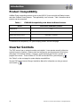
Applicability
These instructions apply to OutBack Power inverter/charger models FXR2012A, FXR2524A, FXR3048A,
VFXR2812A, VFXR3524A, and VFXR3648A only.
Contact Information
Address: 3767 Alpha Way
Bellingham, WA 98226 USA
Telephone: +1 360-435-6030
Website: www.outbackpower.com
Warranty
The warranty for this product can be downloaded from
www.outbackpower.com/resources/warranty/procedures. A printed copy is available by sending a
self-addressed envelope to the above address.
Notice of Copyright
© 2017 by EnerSys. All Rights Reserved.
Trademarks
Trademarks and logos are the property of EnerSys and its affiliates unless otherwise noted. Subject to
revisions without notice. E. & O.E. The UL, ETL, and IEEE trademarks are not the property of EnerSys.
Date and Revision
September 2022, Revision B
Part Number
900-0167-01-01 Rev B

900-0167-01-01 Rev B 3
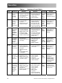
Table of Contents
Introduction ......................................................................................... 7
Audience ................................................................................................................................... 7
Symbols Used ........................................................................................................................... 7
General Safety .......................................................................................................................... 7
Welcome to OutBack Power ..................................................................................................... 8
Inverter Functions ..................................................................................................................... 9
Product Compatibility ......................................................................................................................... 10
Inverter Controls ..................................................................................................................... 10
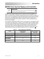
MATE3-Class System Display and Controller .................................................................................... 11
Operation .......................................................................................... 13
LED Indicators ........................................................................................................................ 13
Battery Indicators ................................................................................................................................ 13
Status Indicators ................................................................................................................................. 14
Inverter Functionality ............................................................................................................... 15
AC Input Connection ............................................................................................................... 15
Description of AC Input Modes ............................................................................................... 16
Generator ........................................................................................................................................... 16
Support ............................................................................................................................................... 17
Grid Tied ............................................................................................................................................. 18
Grid Interface Protection Menu ...................................................................................................................... 19
Multi-Phase Coordination ............................................................................................................................... 20
UPS .................................................................................................................................................... 20
Backup ................................................................................................................................................ 20
Mini Grid ............................................................................................................................................. 21
GridZero ............................................................................................................................................. 22
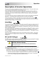
Description of Inverter Operations .......................................................................................... 25
Inverting .............................................................................................................................................. 25
DC and AC Voltages ...................................................................................................................................... 25
AC Frequency ................................................................................................................................................ 26
Search ........................................................................................................................................................... 27
Input .................................................................................................................................................... 28
AC Current Settings ....................................................................................................................................... 28
AC Source Acceptance .................................................................................................................................. 29
Generator Input .............................................................................................................................................. 31
Transfer ......................................................................................................................................................... 31
Battery Charging ................................................................................................................................. 33
Charge Current .............................................................................................................................................. 33
Charge Cycle ................................................................................................................................................. 34
Advanced Battery Technologies .................................................................................................................... 35
Charging Steps .............................................................................................................................................. 35
New Charging Cycle ...................................................................................................................................... 37
Equalization ................................................................................................................................................... 40
Battery Temperature Compensation .............................................................................................................. 40
Offset .................................................................................................................................................. 42
Grid Support ....................................................................................................................................... 43
Auxiliary Terminals ............................................................................................................................. 45
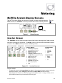
Metering ........................................................................................... 49
MATE3s System Display Screens .......................................................................................... 49
Inverter Screen ................................................................................................................................... 49
Battery Screen .................................................................................................................................... 50

4 900-0167-01-01 Rev B ©2017 EnerSys. All Rights Reserved.
Table of Contents
Troubleshooting ................................................................................. 51
Basic Troubleshooting ............................................................................................................ 51
Error Messages ....................................................................................................................... 56
Warning Messages ................................................................................................................. 57
Temperature Events ........................................................................................................................... 58
GT Warnings ...................................................................................................................................... 58
Disconnect Messages ............................................................................................................. 59
Sell Status ............................................................................................................................... 60
Specifications .................................................................................... 61
Electrical Specifications .......................................................................................................... 61
Mechanical Specifications ....................................................................................................... 64
Environmental Specifications .................................................................................................. 64
Temperature Derating ........................................................................................................................ 65
Regulatory Specifications ....................................................................................................... 65
Listings ............................................................................................................................................... 65
Certifications ....................................................................................................................................... 66
Directives ............................................................................................................................................ 66
Compliance ......................................................................................................................................... 66
Summary of Operating Limits ................................................................................................. 67
Limiting Charge Current (Multiple Inverters) .............................................................................. 67
Firmware Revision .................................................................................................................. 69
Default Settings and Ranges .................................................................................................. 69
Definitions ............................................................................................................................... 79
Index ............................................................................................... 81

900-0167-01-01 Rev B 5
Table of Contents
List of Tables
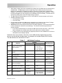
Table 1FXR/HUB Compatibility with Other OutBack Products ............................................ 10
Table 2System Display Compatibility ................................................................................... 11
Table 3Battery Indicator Values ........................................................................................... 13
Table 4Summary of Input Modes ......................................................................................... 24
Table 5Charge Currents for FXR Models ............................................................................ 33
Table 6Offset Interaction with AC Source ............................................................................ 42
Table 7AUX Mode Functions ............................................................................................... 47
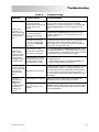
Table 8Troubleshooting ....................................................................................................... 51
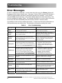
Table 9Error Troubleshooting .............................................................................................. 56
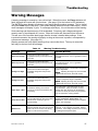
Table 10Warning Troubleshooting ......................................................................................... 57
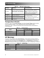
Table 11Inverter Temps ......................................................................................................... 58
Table 12GT Warnings ............................................................................................................ 58
Table 13Disconnect Troubleshooting .................................................................................... 59
Table 14 Sell Status Messages .............................................................................................. 60
Table 15Electrical Specifications for 12-Volt FXR Models ..................................................... 61
Table 16Electrical Specifications for 24-Volt FXR Models ..................................................... 62
Table 17Electrical Specifications for 48-Volt FXR Models ..................................................... 63
Table 18Mechanical Specifications for FXR Models .............................................................. 64
Table 19Environmental Specifications for all FXR Models .................................................... 64
Table 20Operating Limits for all FXR Models ........................................................................ 67
Table 21Chargers On and Current Settings .......................................................................... 68
Table 22Charge Currents for Calculations............................................................................. 69
Table 23FXR Menu Items for 12-Volt Models ........................................................................ 70
Table 24FXR Menu Items for 24-Volt Models ........................................................................ 73
Table 25FXR Menu Items for 48-Volt Models ........................................................................ 76
Table 26Terms and Definitions .............................................................................................. 79

6 900-0167-01-01 Rev B ©2017 EnerSys. All Rights Reserved.
Table of Contents
List of Figures
Figure 1FXR Series Inverter/Charger with Turbo Fan ............................................................ 8
Figure 2LED Indicators ......................................................................................................... 13
Figure 3Inverter Status LED Indicators ................................................................................. 14
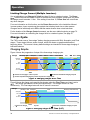
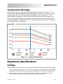
Figure 4Charging Stages Over Time .................................................................................... 34
Figure 5Charging Stages Over Time (24/7) .......................................................................... 34
Figure 6Repeated Charging (1st and 2nd Cycles) .................................................................. 38
Figure 7Repeated Charging (3rd, 4th, and 5th Cycles) ............................................................ 39
Figure 8Grid Support Function Screen ................................................................................. 44
Figure 9Home Screen ........................................................................................................... 49
Figure 10Inverter Screens ...................................................................................................... 49
Figure 11Battery Screen ......................................................................................................... 50
Figure 12AC Test Points ......................................................................................................... 51
Figure 13Temperature Derating .............................................................................................. 65

900-0167-01-01 Rev B
7
Introduction
Audience
This book provides instructions for the functional settings and operation of this product. These
instructions are for use by qualified personnel who meet all local and governmental code
requirements for licensing and training for the installation of electrical power systems with AC
and DC voltage up to 600 volts. This product is only serviceable by qualified personnel. Do not
use this product without reading the FXR Series Inverter/Charger Installation Manual.
Symbols Used
WARNING: Hazard to Human Life
This type of notation indicates that the hazard could be harmful to human life.
CAUTION: Hazard to Equipment
This type of notation indicates that the hazard may cause damage to the equipment.
IMPORTANT:
This type of notation indicates that the information provided is important to the installation,
operation and/or maintenance of the equipment. Failure to follow the recommendations in
such a notation could result in voiding the equipment warranty.
NOTE:
This type of notation indicates useful information. This symbol is not always used.
MORE INFORMATION
This symbol means that more information is available in other literature. If a number is present, it refers to the
corresponding QR code near the beginning of the section. A numbered symbol is also a clickable hyperlink.
General Safety
WARNING: Limitations on Use
This equipment is NOT intended for use with life support equipment or other medical
equipment or devices.
WARNING: Reduced Protection
If this product is used in a manner not specified by FXR product literature, the product’s
internal safety protection may be impaired.
CAUTION: Equipment Damage
Only use components or accessories recommended or sold by OutBack Power or its
authorized agents.

8 900-0167-01-01 Rev B ©2017 EnerSys. All Rights Reserved.
Introduction
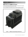
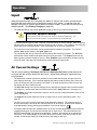
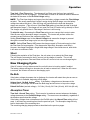
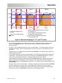
Welcome to OutBack Power
Thank you for purchasing the FXR Series Inverter/Charger. It is designed to offer a complete
power conversion system between batteries and AC power.
As part of an OutBack Power Grid/Hybrid™ system, it can provide off-grid power, grid backup
power, or grid-interactive service which sells excess renewable energy back to the utility.
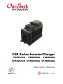
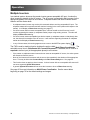
Figure 1 FXR Series Inverter/Charger with Turbo Fan

900-0167-01-01 Rev B
9
Introduction
UPS
Backup
Mini Grid
GridZero
Inverter Functions
oBattery-to-AC inverting which delivers power to run backup loads and other functions
Provides single-phase output
Adjustable range of output voltage
Settable nominal output frequency
oAC-to-battery charging (OutBack Power systems are battery-based)
Accepts a wide variety of single-phase AC sources
oUses battery energy stored from renewable resources
Can utilize stored energy from many sources (PV arrays, wind turbines, etc.)
FLEXmax charge controllers will optimize PV power production as part of a Grid/Hybrid system
oRapid transfer between AC source and inverter output with minimal delay time
oUses the MATE3
S
™ System Display and Controller (sold separately) for user interface as part of a
Grid/Hybrid system
A device from the MATE3s product line (page 11) is required for grid support functionality;
see below
oSupports the OPTICS RE™ online tool
1
for a cloud-based remote monitoring and control application
Requires the MATE3
S
system display
oUses the HUB10.3™ Communications Manager for stacking as part of a Grid/Hybrid system
Stackable in series, parallel, series/parallel, and three-phase configurations
oCertified by ETL to UL 1741 SA17 and SA18, and IEC 62109-1
oGrid support functionality according to the requirements of UL 1741 SA17 and SA18
oField-upgradeable firmware (from www.outbackpower.com); requires MATE3
S
system display
oSeven selectable input modes for different applications
Generator
Support
Grid Tied (available in 24-volt and 48-models only)
oSingle AC input with dual input programming; individualized modes and priorities can be selected
when switching from utility grid to AC generator
External transfer device required
System display required for individual programming
NOTE:
This product has a settable AC output range. In this book, many references to the output
refer to the entire range. However, some references are made to 120 Vac or 60 Hz output.
These are intended as examples only.
1
Outback Power Technologies Intuitive Control System for Renewable Energy

10
900-0167-01-01 Rev B ©2017 EnerSys. All Rights Reserved.
Introduction
Product Compatibility
OutBack Power networking products (such as the HUB 10.3) can work with the Radian inverter
and other OutBack Power products. This applicability is not universal. Table 1 describes which
products can be networked.
Table 1 FXR/HUB Compatibility with Other OutBack Products
Device Can network with Radian products
HUB products Yes
FLEXmax products Yes
Radian (GS series) products Networked, not stacked
SkyBox™, Mojave™, later products No
To determine the compatibility of a system display product, see the next page.
Inverter Controls
The FXR inverter has no external controls pre-installed. It can operate normally without an
external control or interface. Basic modes and settings are pre-programmed at the factory.
(See page 70 for default settings.) However, certain products can monitor, operate, or
program the inverter. These include OPTICS RE and the MATE3S system display.
1
See Table 2 on the next page for system display compatibilities.
See the FXR Series Inverter/Charger Installation Manual for information on wiring a manual
on/off switch.
2
2 1

900-0167-01-01 Rev B
11
Introduction
MATE3-Class System Display and Controller
IMPORTANT:
Some functions are not based in the inverter, but are part of the system display’s firmware.
They will not function if the system display is removed.
Table 2 System Display Compatibility
Device Compatible with
FXR products
Able to connect to
OPTICS RE
MATE3
S
S
y
stem Dis
p
la
y
Yes Yes
MATE3
SL
S
y
stem Dis
p
la
y
Yes No
MATE3 System Display MATE3 revision 002.017.000 or higher is
compatible with FXR revision 001.006.046 or lower No
MATE or MATE2
S
y
stem Dis
p
la
y
No No
AXS Port™ SunSpec
Modbus Interface Yes No
1
The MATE3 class of system display products (sold separately) includes the MATE3, the
MATE3S, and the MATE3SL. Examples in this manual are usually for the MATE3S system
display. This device is designed to accommodate programming and monitoring of a Grid/Hybrid
power system. The system display provides the means to adjust the factory default settings to
correctly match the installation where needed. It provides the means to monitor system
performance and troubleshoot fault or shutdown conditions. It also has web-based interface
functions and data logging.
Once settings are modified with the MATE3S device, it can be removed. The settings are stored
in the inverter’s nonvolatile memory. However, it is recommended to leave the display in place.
It can monitor system performance and respond quickly to correct a fault or shutdown condition.
In the system display, the Profile Wizard is a guided program for rapidly configuring devices.
It prevents the need for repetitive programming when multiple common devices are used.
After collecting user input, it can automatically configure inverters to a series of preset values.
Affected fields include system type, battery charging, and AC source configuration.
1

12 900-0167-01-01 Rev B ©2017 EnerSys. All Rights Reserved.
Introduction
THIS PAGE INTENTIONALLY LEFT BLANK.
.

900-0167-01-01 Rev B
13
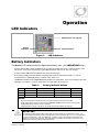
Operation
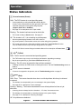
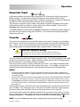
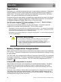
LED Indicators
Figure 2 LED Indicators
Battery Indicators
The BATTERY LED indicators show the approximate battery state. (See IMPORTANT below.)
oA green indicator (F
ULL
) means the batteries have an adequate charge at that time. It does not always mean
they are full. It may be accompanied by a yellow S
TATUS
indicator when an AC source is charging.
oA yellow indicator (OK) means the batteries are somewhat discharged.
oA red indicator (L
OW
) means the batteries are greatly discharged and may require attention. It may be
accompanied by a red S
TATUS
indicator to indicate a low battery error.
oThe
B
ATTERY
indicators and the I
NVERTER
S
TATUS
indicators are independent. They may accompany each other
depending on conditions. Common combinations are noted above and on page 14.
Table 3 Battery Indicator Values
Color 12 Vdc Unit 24 Vdc Unit, ± 0.2 Vdc 48 Vdc Unit, ± 0.4 Vdc Battery Status
GREEN 12.5 Vdc or higher 25.0 Vdc or higher 50.0 Vdc or higher ACCEPTABLE
YELLOW 11.5 to 12.4 Vdc 23.0 to 24.8 Vdc 46.0 to 49.6 Vdc MARGINAL
RED 11.4 Vdc or lower 22.8 Vdc or lower 45.6 Vdc or lower LOW
NOTES:
Gaps in the table (higher-voltage units) are due to the resolution of the inverter’s DC meter.
These voltage settings are not the same as the Low Battery Cut-Out (LBCO) set point. (See page 25.)
The B
ATTERY
indicator settings cannot be changed.
Voltages higher than shown in the Green row usually show that the batteries are charging
.
IMPORTANT:
Due to different system states, battery voltage does not always indicate an accurate state of charge. It is
accurate if batteries have been at rest for several hours at room temperature (25°C or 77°F, or as specified by
the battery manufacturer). If they have any loads, a charging source, or are at another temperature, their
voltage may not reflect their true state. The FLEXnet DC is an OutBack Power battery monitor that can be
added to the system to provide accurate measurements.
Status Indicators
Battery
Indicators
AUX Indicator (see page 45)

14
900-0167-01-01 Rev B ©2017 EnerSys. All Rights Reserved.
Operation
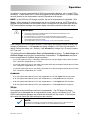
Status Indicators
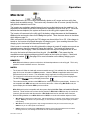
Figure 3 Inverter Status LED Indicators
STATUS INVERTER (Green):
Solid: The FXR inverter is on and providing power.
oIf accompanied by a solid yellow AC IN indicator (2), the
inverter is also connected to the utility grid with an AC input
mode that uses both inverter power and grid power
(Support, Grid Tied, or GridZero).
oSee page 15 for descriptions of AC input modes.
Flashing: The inverter has been turned on but is idle.
oThe inverter is likely in Search mode. See page 27.
Off: The inverter is off. It is not waiting to provide power.
oSee the system display literature to turn the inverter on.
oAny power present is from another source such as the utility grid or generator.
oThe inverter may also be a slave that is in Silent mode due to the Power Save function.
If so, the master inverter may still be providing power to the system.
oSee the FXR Series Inverter/Charger Installation Manual for a description of Power Save.
AC IN (Yellow):
Solid: The AC source is connected and providing power.
oThe FXR inverter may or may not be charging the batteries, depending on settings.
oMay be accompanied by a green STATUS INVERTER indicator (1).
Flashing: The AC source is present but has not been accepted.
oIf flashing continues, the FXR inverter is refusing the source. See the Troubleshooting section on
page 51.
Off: No AC source is detected.
oIf a source is supposed to be present, see the Troubleshooting section on page 51.
ERROR (Red):
Solid: Error. The inverter has shut down due to a critical problem which may be internal
or external.
oThis indicator is accompanied by an error message in the system display.
oSee page 56 for a description of error messages.
Flashing: Warning. The inverter has detected a non-critical problem but has not yet
shut down.
oA warning does not always lead to a shutdown — if it does, it becomes an error.
oThis indicator is accompanied by a warning message in the system display.
oSee page 57 for a description of warning messages.
Off: No problems are detected.
2 1
2

900-0167-01-01 Rev B 15
Operation
Inverter Functionality
The FXR inverter can be used for many applications. Some of the inverter’s operations occur
automatically. Others are conditional or must be enabled manually before they will operate.
Most of the inverter’s individual operations and functions can be programmed using the system
display. This allows customization or fine tuning of the inverter’s performance.
Before operating the inverter:
The operator needs to define the application and decide which functions will be needed.
The FXR inverter is programmed with seven AC input modes. Each mode is optimized for a
particular application. Some modes contain functions unique to that mode.
The modes are described in detail following this section. To help decide which mode will be
used, the basic points of each mode are compared in Table 4 on page 24.
Apart from the input modes, FXR inverters possess a set of common functions or operations.
These operations are described in detail beginning on page 25. Most of these items operate the
same regardless of which input mode is selected. The exceptions are noted where appropriate.
Each distinct mode, function, or operation is accompanied by a symbol representing the inverter
and that operation:
The symbols may have other features depending on the operation.
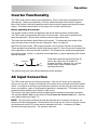
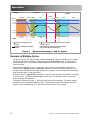
AC Input Connection
The FXR inverter has one set of input connections. Only one AC source can be physically
wired to it at any time. However, two different AC sources can be used with an external transfer
switch. It is common for backup or grid-interactive systems to use the utility grid as the primary
source, but switch to a gas- or diesel-powered generator in emergencies. The inverter can be
programmed with separate input criteria for each source.
The inverter’s two input selections can be programmed for separate input modes (see below).
The selection (Grid or Gen) can be chosen in the AC Input and Current Limit menu. (See the
menu tables beginning on page 70.)
NOTE: The input types are labeled for grid and generator due to common conventions, not
because of inverter requirements. Each selection can accept any AC source as long as it meets
the requirements of the FXR inverter and the selected input mode. If necessary, the Gen
selection can accept grid power. The opposite is also true.
AC
IN
AC
OUT
DC
TRANSFER
These items represent the input from the AC
source, the output to the AC loads, DC
functions (inverting, charging, etc.), and the
transfer relay. Arrows on each symbol
represent power flow.

16
900-0167-01-01 Rev B ©2017 EnerSys. All Rights Reserved.
Operation
Description of AC Input Modes
These modes control aspects of how the inverter interacts with AC input sources. Each mode is
intended to optimize the inverter for a particular application. The names of the modes are
Generator, Support, Grid Tied, UPS, Backup, Mini Grid, and GridZero. The modes are
summarized and compared in Table 4. See page 24. The following pages compare the various
functions of each input mode.
When multiple inverters are stacked together in parallel, the master inverter’s input mode is
imposed on all slaves. (See the stacking section in the Installation Manual.) The slave settings
are not changed; they retain any mode that was previously programmed. However, the slave
will ignore its programmed mode and use that of the master. This also applies to any
parameters in the mode menu (Voltage Limit, Connect Delay, and so on).
Generator
The Generator mode allows the use of a wide range of AC sources, including generators with a
rough or imperfect AC waveform. In other modes, a “noisy” or irregular waveform may not be
accepted by the inverter. Generator allows these waveforms to be accepted. (Self-excited
induction generators may require this mode when used with the inverter.) The charging
algorithm of this mode is designed to work well with AC generators regardless of power quality
or regulation mechanism. The generator must still comply with the inverter’s nominal input
specifications. (See page 28.)
BENEFITS:
o
This mode enables the charging function to tolerate a wider range of generator performance and
waveform irregularities than other modes. See page 30 for recommended generator size parameters.
oGenerator mode can also be used to accommodate grid variability or irregularities. The inverter will
not export power to the grid in this mode.
oA programmable delay timer is available which will allow a generator to stabilize before connection.
In the system display, this menu item is Connect Delay. It is available in both the Grid AC Input
Mode and Limits and the Gen AC Input Mode and Limits menus, depending on which input is
being programmed.
NOTES:
o
Any AC fluctuations that are accepted by the inverter will be transferred to the output. The loads
will be exposed to these fluctuations. It may not be advisable to install sensitive loads under
these conditions.
oThe name of Generator mode does not mean that the inverter requires a generator input when
using this mode. The use of this mode does not require the use of the Gen input type; either
selection can be used. Conversely, the inverter is not required to be placed in this mode just because
a generator is installed.

900-0167-01-01 Rev B
17
Operation
Support
The Support mode is intended for systems that use the utility grid or a generator. In some
cases the amount of current available from the source is limited due to size, wiring, or other
reasons. If large loads are required, the FXR inverter augments (supports) the AC source.
The inverter uses battery power and additional sources to ensure that the loads receive the
power they demand.
In the MATE3s system display, the Grid Input AC Limit dictates the maximum AC draw for the
Grid input. The Gen Input AC Limit sets the maximum draw for the Gen input. The Support
function takes effect if the AC demand on either input exceeds the AC Limit setting.
BENEFITS:
o Large inverter loads can be powered while staying connected to the AC input, even if the input is
limited. The added battery power prevents overload of the input source, but the batteries are not in
constant use.
o The FXR inverter will offset the loads with excess renewable energy if it is available from the
batteries. See page 41 for more information on the Offset function.
NOTES:
IMPORTANT:
The inverter will draw energy from the batteries when the loads exceed the appropriate
AC Limit. With sustained loads and no other DC source, the batteries may discharge to the
Low Battery Cut-Out point. The inverter will shut down with a Low Battery error. (See
pages 25 and 56.) To prevent the loss of power, load use should be planned accordingly.
IMPORTANT:
A “noisy” or irregular AC source may prevent Support from working normally. The inverter
will transfer the power, but will not support the source, charge the batteries, or interact with
the current in any other way. This problem is more common with generators smaller than
the wattage of the inverter.
o Because the inverter limits the current draw from the AC source, it will reduce the charge rate as
necessary to support the loads. If the loads equal the appropriate AC Limit setting, the charge rate
will be zero.
o If the AC loads exceed the AC Limit setting, the Support function is activated. Instead of charging,
the inverter will take power from the batteries and use it to support the incoming AC current.
o The Support function is not available in any other input mode.
o This mode should not be used in a stacked system that uses slave inverters.

18
900-0167-01-01 Rev B ©2017 EnerSys. All Rights Reserved.
Operation
Grid Tied
IMPORTANT:
Selling power to the utility company requires the authorization of the local electric jurisdiction.
How the utility company accommodates this will depend on their policies on the issue. Some
may pay for power sold; others may issue credit. Some policies may prohibit the use of this
mode altogether. Please check with the utility company and obtain their permission before
using this mode.
The Grid Tied mode allows the inverter to become grid-interactive. This means that in addition
to using power from the utility grid for charging and loads, the inverter can also convert excess
battery power and sell it to the utility grid. Excess battery power almost always comes from PV
arrays, but may come from other sources such as wind and hydroelectric turbines.
o
The grid-interactive function uses the following items:
Offset operation. See page 41 for more information.
Grid Support settings. See page 43 for more information.
BENEFITS:
o
Excess power is returned to the utility grid.
The inverter will offset the loads with excess renewable energy if it is available from the batteries.
If the excess energy is greater than the AC (load) demand, the excess will be sold to the grid.
NOTES:
o
The inverter has a delay before selling will begin. This function, the Re-Connect Delay Timer, has a
default setting of five minutes. During this time, the inverter will not connect to the utility grid. The
timer is adjustable in the Grid Interface Protection menu (see below).
o Upon initial connection to the utility grid, the inverter may be required to perform a battery charging
cycle. This may delay the operation of the grid-interactive function.
o The grid-interactive function only operates when excess DC (renewable) power is available.
o The grid-interactive function is not available in any of the other input modes.
o This mode is not available in 12-volt FXR models. It does not appear on the system display’s list of
available input modes.
o Whenever energy produced from the renewable energy source exceeds the loads on the inverter
output, the system display will indicate selling. Any power not consumed by loads on the main panel
will be sold to the grid.
o The amount of power an inverter can sell is not necessarily equal to its specified output wattage.
The Maximum Sell Current can be decreased if it is necessary to limit the power sold. This item is
available in the Grid Interface Protection menu (see next page). This setting is not affected by the
AC Limit settings (see page 28).
The amount of power that is sold is controlled by the utility grid voltage. The wattage sold equals
this voltage multiplied by the current. For example, if the inverter sells 15 amps and the voltage is
116 Vac, the inverter will sell 1.74 kVA. If the voltage is 125 Vac, the inverter will sell 1.88 kVA.
Additionally, output will vary with inverter temperature, battery type, and other conditions.
This recommendation is specifically for the inverter’s grid-interactive function. In some cases, the
source may be sized larger to account for environmental conditions or the presence of DC loads.
This depends on individual site requirements.

900-0167-01-01 Rev B 19
Operation
Grid Interface Protection Menu
Grid-interactive requirements vary in different locations around the world. The grid-interactive
settings are adjustable in the Grid Interface Protection and Grid Support menus. These
menus are only available with installer-level access. These settings are generally controlled by
the local authorities or interconnection agreement and should not be altered by the end user.
The installer password must be changed from the default to access these settings. Once it has
been changed, the settings can only be accessed with the installer password.
This menu includes the following:
oOperating Frequency. It can be selected to either 50 or 60 Hz. This setting changes the inverter’s
output frequency, but it also changes the input (and grid-interactive) acceptance parameters. See
page 26 for more information on the inverter’s frequency.
oClearance Time during power loss.
oCoordinated AC Connect/Disconnect. See Multi-Phase Coordination on the next page.
oMaximum Sell Current when exporting power to the utility.
oThe Grid Support menu contains multiple voltage, frequency and time parameters for operation.
The grid-interactive function can only operate while the grid is stable and within specific limits.
In Grid Tied mode, the inverter operates in accordance with the Grid Support settings. If the
AC voltage or frequency vary outside these limits, the inverter will disconnect to isolate itself and
its protected loads. Grid Support settings adhere to specific standards, such as California's Rule
21 or HECO Rule 14H. These limits override the AC source acceptance limits on page 29, which
are used in most other modes. See page 43 for more information on the Grid Support function.
Before operating in Grid Tied mode, be sure to obtain any necessary interconnection
agreements or related documents from the utility company or local building authority. These
documents will typically specify the grid support and interface protection settings that must be
used for that installation.
The Grid Support menu has a Regulatory Specification screen that displays the standard
currently loaded on the system and the settings loaded into the Grid Support options from a .GIP
file. (See below.) The default standard (and setting) is IEEE 1547.
The items in the following list are the selectable Grid Support options. The utility company may
need to review these items to make certain their standards are met.
Low and High Voltage and Frequency Ride-Through
Fixed Power Factor
Ramping
If the grid is outside the parameters of the applicable standard, the inverter disconnects from the
AC source. It will not reconnect until the source meets the voltage and frequency Reconnect
Parameters for the duration of the timer in that menu.
If the inverter stops selling or disconnects due to Grid Interface Protection, the system display
will show the reason. Sell Status messages are listed on page 60. Disconnect messages are
listed on page 59. Often these messages will be the same.
NOTE FOR 12-VOLT MODELS: The Grid Interface Protection menu is still present due to the
need for certain items such as Operating Frequency. The Grid Support menu settings are present
due to their applicability in GridZero mode (see page 22), but they are only used in that mode.
oUpload Grid Protection. This screen automatically loads a “package” of grid support settings from
a .GIP file. See the FXR Series Inverter/Charger Installation Manual for instructions.
1
2
oSee Table 23 beginning on page 70 for the locations and settings of all menu items in MATE3s
menus, including those on this page.
1
Frequency Watt
Volt Watt
Volt/VAr

20 900-0167-01-01 Rev B ©2017 EnerSys. All Rights Reserved.
Operation
Multi-Phase Coordination
Several other inverter adjustments are located in the Grid Interface Protection menu. These
sensitive items can only be changed with installer-level access.
The FXR inverter’s stacking function includes the option called Multi-Phase Coordination.
The selectable menu item is Coordinated AC Connect/Disconnect. The default setting is No.
oIf selected to No, the inverters will connect independently to the AC source. If certain inverters do not
sense an acceptable source, only those inverters will disconnect and return to the inverting state (with
a Phase Loss warning). Other inverters will remain connected. See page 31 for more information.
oIf selected to Yes, the AC source is required to deliver appropriate input to all inverters in a stacked
system. If the master or subphase master inverters do not sense an acceptable AC source, the entire
system disconnects from the source. None of the inverters will reconnect until the source is
acceptable for the duration of the appropriate timer. See page 31 for more information.
When reconnecting:
oIf the inverter is in Grid Tied mode, the Reconnect Delay timer is used.
oIf the inverter is any other AC input mode, the Connect Delay timer is used.
See pages 28 and 31 for more information on input acceptance and the transfer function.
See the Installation Manual for more information on the stacking function and subphase master
inverters. See the tables beginning on page 70 for the default settings and ranges.
UPS
In UPS mode, the parameters have been optimized to reduce the response time. If the utility
grid becomes unstable or is interrupted, the inverter can transfer to inverting with the fastest
possible response time. This allows it to support sensitive AC loads with minimal interruption.
BENEFITS:
oConstant power is provided to the loads with virtually no drop in voltage or current.
NOTES:
oDue to the need for the FXR inverter to react quickly to AC source fluctuations, it must remain fully
active at all times. The inverter requires a continuous consumption of 42 watts.
oFor this reason, the Search function does not operate in this mode. (See page 27.)
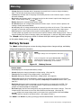
Backup
The Backup mode is intended for systems that have utility grid available as the primary AC
source. This source will pass through the FXR inverter’s transfer circuit and will power the
loads unless utility power is lost. If utility grid power is lost, then the inverter will supply energy
to the loads from the battery bank. When the utility power returns, it will be used to power the
loads again.
BENEFITS:
oThis mode will continuously maintain the batteries in a fully-charged state. It does not have the
overhead consumption of the UPS mode.
Failure
Failure
Page is loading ...
Page is loading ...
Page is loading ...
Page is loading ...
Page is loading ...
Page is loading ...
Page is loading ...
Page is loading ...
Page is loading ...
Page is loading ...
Page is loading ...
Page is loading ...
Page is loading ...
Page is loading ...
Page is loading ...
Page is loading ...
Page is loading ...
Page is loading ...
Page is loading ...
Page is loading ...
Page is loading ...
Page is loading ...
Page is loading ...
Page is loading ...
Page is loading ...
Page is loading ...
Page is loading ...
Page is loading ...
Page is loading ...
Page is loading ...
Page is loading ...
Page is loading ...
Page is loading ...
Page is loading ...
Page is loading ...
Page is loading ...
Page is loading ...
Page is loading ...
Page is loading ...
Page is loading ...
Page is loading ...
Page is loading ...
Page is loading ...
Page is loading ...
Page is loading ...
Page is loading ...
Page is loading ...
Page is loading ...
Page is loading ...
Page is loading ...
Page is loading ...
Page is loading ...
Page is loading ...
Page is loading ...
Page is loading ...
Page is loading ...
Page is loading ...
Page is loading ...
Page is loading ...
Page is loading ...
Page is loading ...
Page is loading ...
Page is loading ...
Page is loading ...
-
 1
1
-
 2
2
-
 3
3
-
 4
4
-
 5
5
-
 6
6
-
 7
7
-
 8
8
-
 9
9
-
 10
10
-
 11
11
-
 12
12
-
 13
13
-
 14
14
-
 15
15
-
 16
16
-
 17
17
-
 18
18
-
 19
19
-
 20
20
-
 21
21
-
 22
22
-
 23
23
-
 24
24
-
 25
25
-
 26
26
-
 27
27
-
 28
28
-
 29
29
-
 30
30
-
 31
31
-
 32
32
-
 33
33
-
 34
34
-
 35
35
-
 36
36
-
 37
37
-
 38
38
-
 39
39
-
 40
40
-
 41
41
-
 42
42
-
 43
43
-
 44
44
-
 45
45
-
 46
46
-
 47
47
-
 48
48
-
 49
49
-
 50
50
-
 51
51
-
 52
52
-
 53
53
-
 54
54
-
 55
55
-
 56
56
-
 57
57
-
 58
58
-
 59
59
-
 60
60
-
 61
61
-
 62
62
-
 63
63
-
 64
64
-
 65
65
-
 66
66
-
 67
67
-
 68
68
-
 69
69
-
 70
70
-
 71
71
-
 72
72
-
 73
73
-
 74
74
-
 75
75
-
 76
76
-
 77
77
-
 78
78
-
 79
79
-
 80
80
-
 81
81
-
 82
82
-
 83
83
-
 84
84


OutBack Power FXR / VFXR A Series User manual
- Type
- User manual
- This manual is also suitable for
Ask a question and I''ll find the answer in the document
Finding information in a document is now easier with AI
Related papers
-
OutBack Power FLEXpower TWO FXR User manual
-
-
-
-
-
-
-
-
-