=
SALEEN SPEEDLAB
SUSPENSION KIT
INSTALLATION MANUAL: 2005 Mustang
P/N: 10-8002-C11790A
Saleen Performance, Inc. 76 Fairbanks Irvine, CA 92618 949-597-4900
www.saleen.com

2
IF YOU ARE NOT EXPERIENCED IN THE
AREA OF AUTOMOTIVE MECHANICS, WE
STRONGLY URGE THAT YOU REFER THIS
INSTALLATION TO A CERTIFIED INSTALLER
OR TECHNICIAN

3
Saleen Speedlab Suspension Kit
Installation Guide for 2005 Mustang
WELCOME!
Thank you for buying the Saleen Speedlab Suspension Kit for the 2005 Mustang. We
appreciate your business, and we hope you enjoy your product.
For your benefit, please read the following instructions completely and thoroughly before
attempting to install the suspension kit. Many questions we have received from customers
about the installation of our products could have been easily solved by information listed
in the accompanying installation guide. We want you to enjoy the product in its fully
functional state, and reading this tutorial is a great first step to getting you on your way to
a more rare and better handling Mustang.
NOTE: Please keep all hardware you remove from your stock Mustang, as much of it will
be reused to install the new suspension kit pieces.
Please take caution in installing this kit; the car will be up on jack stands and the car can
fall and cause serious injury if not properly placed on jack stands.
Again, thank you for choosing Saleen!

4
Table of Contents
Saleen Chassis Fasteners and Torques…………………………………..6
I Wheel Removal…………………………………….…………….………7
II Front Struts Removal………………………………………..…...…….8
III Front Sway Bar Removal……………………………………..…...….10
IV Front Strut Subassembly…………………………………….…...…...11
V Front and Rear Shock Decal Installation…………………….….……13
VI Front Struts Installation…………………….…………………..….…14
VII Front Sway Bar Subassembly………..………….…...……….….….15
VIII Front Sway Bar Installation…………………….…...……….…….16
IX Rear Suspension Removal……….……………….…...……….….….17
X Rear Suspension Installation……..……….……….…...……….…….18

5
OBTAIN THE FOLLOWING TOOLS:
• Spring compressor
• 10 mm wrench
• ¼” wrench
• ½” drive Ft-lb torque wrench
• ½” drive impact gun
• ½” drive 13/16” deep socket
• ½ ” drive 13mm deep socket
• ½ ” drive 15mm deep socket
• ½ ” drive 15 mm shallow wobbly socket
• ½” drive 18mm deep socket
• ½ ” drive 21 mm deep socket
• 3/8” drive impact gun
• 3/8” drive 10mm socket
• 3/8” drive 13mm deep socket
• 3/8” drive 15mm deep socket
• 3/8” drive 15 mm shallow wobbly socket
• 3/8” drive 18mm deep socket
• Tape measure
• Grease
• Small flat head screw driver
• Needle nose pliers
•
Hack saw
•
Polyurethane grease intended for automotive
application

6
The following table lists the proper torque values to follow when fastening all suspension
components; note also the recommendations for the use of Loctite in the last column.
Saleen Chassis Fasteners and Torques
Ref
Number
(B)olt
(N)ut
(F)itting Qty Joint description
Min Spec
Torque
(Nm)
Nom
Spec
Torque
(Nm)
Max Spec
Torque
(Nm)
Min Spec
Torque
(lbf-ft)
Nom Spec
Torque
(lbf-ft)
Max Spec
Torque
(lbf-ft)
Locktite (L)
Nilock (N)
MechLck (M)
DefNut (D)
Plain (P)
1
N 2 front strut to mount 53.1
62.5
71.9 39.2
46.1
53.0 N
2
N 8 front strut mount to body 29.7
35
40.3 21.9
25.8
29.7 P
3
N 2 Linkage to strut 97.7
115
132.3 72.1
84.8
97.6 N
4
B 4 knuckle to strut 170
200
230 125.4
147.5
169.6 P
5
N 2 sta-bar to linkage 97.7
115
132.3 72.1
84.8
97.6 N
6
N4
sta-bar brackets to #1 x-
member
59.5
70
80.5 43.9
51.6
59.4 P
7
N 2 rear shock to body 34
40
46 25.1
29.5
33.9 P
8
B2
rear shock to rear axle
Torque at Ride Height
97.7
115
132.3 72.1
84.8
97.6 N
9
B2
CAPSCRW SCKT HD
M12x1.75x75mm ST
103
130
155 76.0
95.9
114.3 L
10
B 2 front caliper mounting bolt 87.5
103
118.5 64.5
76.0
87.4 L
11
B 4 jounce bumper brkt to axle 28
30
32 20.7
22.1
23.6 P
12
N 20 Lug Nuts 113
133
153 83.3
98.1
112.8 P
13
N 4 Rear Stabilizer Bar to Axle 59.5
70
80.5 43.9
51.6
59.4 P
14
B 2 Rear Stabar Link to Body 97.7
115
132.3 72.1
84.8
97.6 N

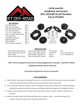
7
I Wheel Removal
Figure 1
Order of Operations:
1. Jack up the front of the car, and place
jack stands underneath the chassis
members.
2. Lower the car onto the jack stands.
The car should stay in this position
for the entire front suspension
replacement.
3. Remove five 13/16” nuts using the
1/2” air gun and 13/16” deep socket.
(Figure 1) Be careful when you
remove the last nut, as the wheel
could fall off.
4. Remove wheel; repeat on other side
of car.
Obtain the following tools:
• 13/16” deep socket, ½” drive
• ½” impact gun

8
II Front Struts Removal
Figure 1
Order of Operations:
NOTE: Keep ALL hardware for
installation of new suspension
components.
1. Remove the two lower strut bolts
using a 3/8” impact gun with a 18mm
deep socket. (Figures 1 and 2)
2. Unbolt the end link from the strut
using the 3/8” impact gun with the
18mm socket. (Figure 3)
Obtain the following tools:
• ½” drive impact gun
• 13/16” deep socket, ½” drive
• 3/8” drive impact gun
• 15mm deep socket, 3/8” drive
• 18mm deep socket, 3/8” drive
• 13mm deep socket, 3/8” drive
• 10mm socket, 3/8” drive
Figure 3
Figure 2

9
Figure 5
3. Unbolt the brake line from the strut
using the 3/8” impact with the 10mm
socket. Remove the Christmas tree
that holds the ABS line in place.
(Figure 4)
4. Using the 13 mm deep socket and
3/8” drive impact gun, remove the
nuts from the four upper strut bolts
(in the engine bay). (Figure 5)
5. Carefully maneuver the strut out of
the wheel well so that it does not hit
the brake lines.
6. Keep the strut; you will need parts of
it to complete the assembly of the
new front strut.
7. Repeat steps 1 – 6 to remove the front
strut from the other side of the car.
Figure 4

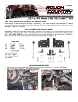
10
III Front Sway Bar Removal
Figure 1
Figure 2
Order of Operations:
NOTE: Keep all hardware for
installation of new suspension
components.
1. Remove the bolt that connects the
sway bar to each end link using a
3/8” impact gun with the 18mm
socket. (Figure 1)
2. Remove the four bolts under the
chassis holding the sway bar
bushings brackets in place. Use a
3/8” impact gun with a 15mm socket.
(Figure 2)
3. Remove stock front sway bar.
Obtain the following tools:
• 3/8” drive impact gun
• 15mm socket, 3/8” drive
• 18mm socket, 3/8” drive

11
IV Front Strut Subassembly
Part Number Description Qty.
06-1302-C09816a Strut Front Coupe
2
06-1302-C09731a Spring Front Coupe
2
Figure 1
Figure 2
Order of Operations:
NOTE: THE FOLLOWING
OPERATION IS DANGEROUS. IF
YOU HAVE NOT
SUCCESSFULLY COMPLETED
THE SUBBASSEMBLY OF A
STRUT BEFORE, LEAVE THE
SUBASSEBLY TO A
PROFESSIONAL.
1. Place the stock strut in the spring
compressor. Place the bottom end of
spring on the three lower clamps,
making sure to tilt it toward the rear
enough to place the impact wrench
and 21 mm socket onto the central
nut on top of the strut assembly.
(Figure 1)
2. Remove the 21mm nut and the strut
cap from the top of the stock strut. Be
careful when you remove the bolt;
sometimes the shock and spring will
fall to the ground. (Figure 2)
Obtain the following tools:
• ½” drive impact
• 1/2” drive 21 mm deep socket
• Spring compressor
• Hack saw
• Ft-Lb Torque Wrench, ½”
drive

12
Figure 4
Figure 5
4. Obtain the bump stop from the stock
strut, and cut it with a hack saw at the
line shown in Figure 3 (bump stop on the
right in Figure 3 is before, and the one on
the left after, the cut has been made).
5. Obtain the new shock and spring. Place
modified bump stop over the shock
(Figure 2).
6. Cover the new spring with the rubber
boot. Place the spring over the new shock
- NOTE ORIENTATION IN FIGURE 2
- and cover with the stock cap (Figure 2).
Place this assembly in the spring
compressor as you did for the stock strut.
(Figure 3)
7. Align the notch on the cap with the bolt
holes at the bottom of the strut. (Figure
4)
8. Compress the Saleen Racecraft strut
assembly.
9. Apply a dab of red Loctite to the threads
of the center stud. Use the stock 21mm
nut to tighten the cap on to the new
tower. (Figure 5) There should be at least
a few threads above the nut when the
strut is fully tightened. Torque center
strut nut to 46 ft-lbs.
Figure 3
Cut line

13
V Front and Rear Shock Decal Installation
Part Number Description Qty.
06-1302-C09816 Strut Front Coupe
2
06-1302-B09916* Shock Rear Coupe
2
06-9101-C10227 Decal Shock N2 Racecraft
4
Figure 1
Figure 2
Order of Operations:
1. Take the shock, position it as shown in
Figure 1, and place the logo as seen, one
inch from the bottom of the shock.
2. The front strut decal needs to be one inch
off the top of the lower bolt holes.
(Figure 2)
Obtain the following tools:
• Tape measure
1 inch
Bottom
of rear
shock
Front strut
1 inch

14
VI Front Struts Installation
Part Number Description Qty.
06-1302-B09913* Strut Front Assembly Coupe
2
Figure 1
Figure 2
Order of Operations:
1. With notch facing outside of the
vehicle, slide studs in top of strut into
four upper mounting holes; be sure
the brake line sits behind strut
assembly before tightening the strut
in place. (Figure 1)
2. Use a 13mm deep socket with the
3/8” impact gun to tighten a nut over
each of the four studs (Figure 5, p. 8).
Torque to 26 ft.-lbs.
3. Pull up wheel hub and attach the
bottom of the strut to the knuckle
using stock bolts and nuts. Use the
3/8” impact gun and 18 mm deep
socket to tighten (Figure 2). Torque
to 148 ft-lbs.
4. Put the sway bar end link stud into
rear most hole on strut tower, tighten
using a ½” impact gun with a 18mm
deep socket. (Figure 3) Torque to 85
ft-lbs.
5. Bolt brake line to rear of strut tower
using 10mm socket and 3/8” impact
gun. (Figure 5)
Obtain the following tools:
• ½” impact gun
• 18mm deep socket, ½” drive
• 3/8” impact gun
• 18mm deep socket, 3/8” drive
• ¼” air wrench
• 13 mm deep socket, 1/4”
drive
• 13 mm deep socket, ½” drive
• 10 mm deep socket, ¼” drive
• Ft-Lb torque wrench, ½”
drive
Figure 3
Rear of
vehicle
End
link

15
VII Front Sway Bar Subassembly
Part Number Description Qty.
06-1303-C09503 Swaybar Front
1
00-1303-C09515* Bushing Swaybar Front
2
00-1303-C09932* Bracket Bushing Swaybar Front
2
Fi
g
ure 1
Figure 2
Order of Operations:
1. Grease the bushings. (Figures 1 and
2)
2. Push bushings in towards the idle of
the sway bar until they hit the outside
of the flange. (Figure 3)
3. Place the bracket with the zert fitting
over the bushing and push until the
bracket lies flush with the flat end of
the bushing (Figure 4).
Figure 3
Figure 4
Obtain the following tools:
• Polyurethane grease intended
for automotive application
Push bushing
into flange

16
VIII Front Sway Bar Installation
Part Number Description Qty.
06-1303-B09915* Swaybar Front Assembly 1
Figure 1
Figure 2
Order of Operations:
1. Put the new sway bar into the
location where the stock sway bar
went.
2. Align the bushing brackets over the
existing studs. (Figure 2)
3. Fasten down the new sway bar using
the stock nuts over the inboard studs
and new bushings brackets. There are
a total of four nuts. Use a 3/8” impact
gun with a 15 mm socket. (Figure 2)
Torque nuts to 52 ft-lbs.
4. Attach the ends of the sway bar to the
bottom of the end links, and put the
stock nut in place over each bottom
end link stud. Tighten nut using the
3/8” impact gun and 18 mm deep
socket. Torque nuts to 85 ft-lbs.
5. Remove the white cover from the
front strut decals.
6. Jack the front of the car up, remove
the jack stands, and lower the car
back to ride height.
Obtain the following tools:
• 3/8” impact gun
• 15 mm deep socket, 3/8” drive
• 18 mm deep socket, 3/8” drive
• Ft-lb torque wrench, ½” drive
• 15 mm deep socket, ½” drive
• 18 mm deep socket, ½” drive
Front of
car

17
IX Rear Suspension Removal
Figure 1
Order of Operations:
NOTE: Keep ALL hardware and
rubber spring boots for installation
of new suspension components.
1. Jack up the rear of the car and place
jack stands under the chassis
members near the rear suspension.
2. Lower the car onto the jack stands
and make sure the car is secure.
3. Remove rear wheels using the ½”
impact gun with a 13/16” socket.
4. Remove two rear sway bar
connections that are near the lower
shock mounting points using a 3/8”
impact gun with a 15mm socket.
(Figure 1)
5. Remove lower shock bolt, one per
shock, using a 3/8” impact gun with a
15mm socket. (Figure 1)
Obtain the following tools:
• ½” drive impact gun
• 13/16” deep socket, ½ “ drive
• 3/8” Impact gun
• 15mm short wobbly socket,
3/8” drive
• ¼” wrench
Bottom of
rear shock

18
Figure 3
6. Let the axle hang. Note the
orientation of the rear springs, how
there is a shortened vertical distance
between each of the coils at the top of
the spring.
7. Work the springs out of place. Pop
the bottom end toward the front of
the vehicle, and pull the spring out.
(Figure 2)
8. In the trunk, pull back the forward
corners of the trunk liner to expose
the top of the shock mounts. Use a
3/8” impact gun with a 15mm deep
socket to remove the nut atop the
strut. The strut should fall out if the
wheels are off the ground. (Figures
3,4) If the nut won’t come off the top
of the shock because the shock is
rotating with the impact gun, place
more weight on the bottom of the
shock/wheel hub.
Fi
g
ure 2
Figure 4

19
X Rear Suspension Installation
Part Number Description Qty.
06-1302-C09818 Shock Rear Coupe
2
06-1302-C09819 Spring Rear Coupe
2
Figure 1
Figure 2
Order of Operations:
1. Place the top of the spring (the end with
the shorter vertical distance between
coils) into the mounting location, making
sure the stock rubber boot is in place.
The top of the spring has shortened
vertical distances between the coils.
Install both springs before next step.
Make sure to use the stock rubber boots
on top and bottom of the springs. (Figure
1)
2. Put the bottom of the shock into the
bolting location. With the top lined up
with the trunk hole, tighten bottom of
shock. Decal faces rear fascia. Use a 15
mm socket with a 3/8” impact gun.
(Figure 2) Repeat on other side.
3. Remove the white cover from the shock
decal.
Obtain the following tools:
• 3/8” impact socket
•
15 mm shallow wobbly
socket, 3/8” drive
• Small flat head screw driver
• Needle nose pliers
• 13/16 deep socket, ½” drive
• 10 mm wrench
• Hack saw
• Ft-lb torque wrench, ½” drive

20
4. The bump stop has to be modified.
Figure 3 shows the unmodified bump
stop with the proper cut line, and
Figure 4 shows the modified bump
stop.
5. With a hack saw, cut both rear bump
stops at the cut line, in the bottom of
the two rings in the bump stop
molding.
6. Reinstall the stock sway bar. Fasten
the two 15 mm stock bolts and nuts
with a 3/8” impact gun. (Figure 5)
Torque nuts to 52 ft-lbs.
7. Use the stock nuts and rubber hats to
fasten the top of shock to the
mounting point in the interior of
trunk. Use the 15mm wobbly socket
with a 3/8” impact gun. (Figure 6)
Torque nuts to 30 ft-lbs.
8. Torque the bolts at the bottom of
each shock to 85 ft-lbs, with the
wheel hub at ride height.
9. Replace the wheels, torque the lug
nuts to 98 ft-lbs, and remove the jack
stands.
Figure 3
Fi
g
ure 4
Figure 5
Figure 6
Tighten with
15mm wobbly
/