Page is loading ...

3-Channel Receiver Model 7433E
SPECIFICATIONS
Output Rating..................................................5 Amps 28VAC or DC Max.
Power.........................................................................18V to 35V, @ 30ma
RF Frequency...........................................................................433,92MHz
If the power is other than shown in specifications, an accessory transformer
is required. Model 86LM Coaxial Cable Kit is also available.
Accessory Transmitters – Series 4330.
Universal receiver Model 7433E can be used with up to four
Model Series 4330 “Smart” remote controls per channel.
The receiver can be used with a multi-function remote control to
operate three residential garage door openers, or with a three-
button door control to OPEN, CLOSE or STOP a commercial
garage door opener. Not for use on residential fail-safe operators.
Both the receiver and the antenna use TV Type F coaxial
connectors. The antenna can be plugged directly onto the
receiver or mounted to a bracket and connected to the receiver
with Model 86LM Coaxial Cable Kit, if you need more range.
Select a location for the receiver which allows access to the
terminals and space for the antenna (as far from metal structures
as possible and preferably with the antenna in an upright
position). Fasten the receiver securely with screws through the
two holes provided in the cover flanges.
Children operating or playing with a garage door
opener can injure themselves and others. The
garage door could close and cause serious injury or
death. Do not allow children to operate the door control push button or
the remote control transmitters.
Install the receiver (and all door control push buttons) out of the reach
of children and away from all moving parts of the door and door
hardware, but where the garage door is visible.
This radio receiver incorporates constant closure contacts, and thus
use on residential operators incorporating fail-safe infra-red sensors is
prohibited.
Disconnect power to the opener(s) before installing the receiver.
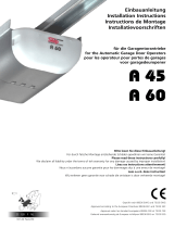
Garage door opener #1 (without transformer). See Figure 1:
Connect paired grey receiver wires to the opener terminal screws
used for the wall push button.
Also, connect bell wire to receiver terminal 1 and opener terminal
screw 1; and receiver terminal 2 and opener terminal screw 3.
Garage door opener #1 (with transformer). See Figure 2:
Connect bell wire to receiver terminal screws 1 and 2, and to
transformer terminals. Also, connect paired grey receiver wires to
opener terminal screws used for wall push button.
Garage door opener #2: Connect paired yellow wires from the
receiver to the opener terminal screws used for the wall button.
Garage door opener #3: Connect paired blue wires from the
receiver to the opener terminal screws used for the wall button.
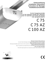
Use a screwdriver to pry open the receiver cover. See Figure 3.
Set the slide switch to the N.O. position If this is not done,
opener #1 may not operate properly.
Re-connect power to the opener(s) and to the transformer, if used.
• Select a remote push button to operate garage door opener #1.
• Press and
hold
the selected remote button.
• Press and release the “smart” button labeled “A” on the
receiver. The adjacent indicator light will flash.
• Release the remote push button.
Opener #1 will now operate when the selected remote control
push button is pressed.
Repeat the procedure with the other two remote push buttons to
program the second opener (“smart” button “B”) and the third
opener (“smart” button “C”).
Return the cover to the receiver.
Note: If opener #1 won’t run, check to be sure the slide switch
on the receiver is set to the N.O. position.
1
2
3
1
2
3
Receiver
(Bottom)
Paired grey receiver wires
Operator
24 v
Trans
Primary
4
Common
Relay
Wall
Button
Figure 1
Figure 2
ABC
OPENING RECEIVER
Select a remote control push
button to operate each opener
Connect
Antenna
Opener #3
(Blue)
Opener #2
(Yellow)
Opener #1
(Grey)
Slide Switch – N.O. Position
Figure 3
To use the receiver to operate three garage door openers
with a multi-function remote control:
1
2
3
1
3
Receiver
(Bottom)
Wall
Button
Operator
24 v
Trans
Primary
4
Common
2
Relay
Transformer
Paired grey receiver wires
Declaration of Conformity
Universal Radio Receiver...........................................................................Model No.7413E, 7433E
are in conformity to the applicable sections of Standards............................................ETS 300 683,
per the provisions & all amendments of the EU Directives ............................................89/336/EEC
Declaration of Incorporation
Universal Radio Receiver Model Nos. 7413E and 7433E, when installed and maintained according
to all the Manufacturer’s instructions in combination with a Garage Door Opener and Garage Door,
which have also been installed and maintained according to all the Manufacturer’s instructions,
meets the provisions of EU Directive 89/392/EEC and all ammendments.
I, the undersigned, hereby declare that the equipment specified above and any accessory
listed in the manual conforms to the above Directives and Standards.
Chamberlain GmbH
D-66793 Saarwellingen
October 1996
Colin B. Willmott
Chefingenieur
GB
114A2137B © 1999, Chamberlain GmbH All Rights Reserved
4
/