Page is loading ...

&HOOXODU $ 5 8
3UR7DON
INSTRUCTION MANUAL
1272M001
Manual Revision: 7 - July 2002

Contents
1. Operations Overview
Cv2 capabilities ...........................1-1
What constitutes an alarm? .................1-1
How are alarms processed? .................1-2
What actions should occur when an
alarm is detected? ...................1-3
How do you want to respond to an
alarm call?..........................1-4
What if an alarm is not acknowledged? .......1-5
What do you want the Cv2 to do when
you call it?..........................1-5
Sending remote control commands ..........1-5
Indicators ..............................1-6
Troubleshooting ..........................1-6
2. Installation
Antenna requirements .....................2-1
Mounting ................................2-1
Input port connections .....................2-2
Output port connections ...................2-4
Configuration programming connection .......2-4
3. Configuration with the PC
PC requirements ..........................3-1
Installing the program......................3-1
Starting the configuration program...........3-1
The desktop ..............................3-1
Configuring the Cv2 .......................3-3
Hardware...........................3-3
Points .............................3-5
Groups .............................3-12
Directories..........................3-15
General ............................3-17
Configuration programming.................3-18
4. Voice Storage and Configuration with the Telset
Setup ...................................4-1
Access ..................................4-1
Commands ...............................4-1
Telset programming summary...............4-5
5. Specifications
General ..................................5-1
Programming features .....................5-1
Telephone ...............................5-2
Options..................................5-2
6. Warranty ...................................6-1

Operations Overview 1-1
B1272M001
BARNETT ENGINEERING LTD. ProTalk Cv2
1. Operations Overview
The purpose of this chapter is to provide an overview of the Cv2 capabilities. Chapter topics are
organized in the same order that you would follow in setting up the system. Read this chapter
carefully before proceeding with the installation and programming of the Cv2. For more details
on configuring the operation through the programming software, refer to Chapter 3,
Configuration.
1.1 Cv2 Capabilities
When an alarm occurs, the Cv2 places a call using its built-in cellular phone and announces
the alarm condition using stored voice messages. Alarm messages consist of the site ID
phrase, the group phrase and the alarm message phrase that are stored at voice programming
time. The group phrase is used if the alarms have been grouped to provide different activities
for different alarm conditions. The unit can also be called up and interrogated to obtain
current alarm conditions and readings.
The Cv2 has eight hardware inputs that can be programmed to accept either digital or analog
signals and eight hardware outputs. Inputs can be independently configured to operate in
these modes:
digital monitoring contact closures or voltage levels
watchdog monitoring for the absence of a periodic event
totalizer counting events
interval measuring the time duration of events
analog measuring 0 to 5 volt signals
Outputs can be set to operate as either on/off controls or as timed controls.
1.2 What constitutes an alarm?
Alarm conditions can be defined for digital, watchdog and analog inputs. Totalizers and
interval inputs are used for measurement purposes and do not generate alarms. The signal at
the input is conditioned by a debounce timer that ensures the level is valid before accepting it.
A digital input has normal and alarm states that can be defined as either when the input is high
or low. After the input signal has been qualified by the debounce timer, it can be registered as
an alarm when the input is active, or it can be latched to detect a pulsed condition. The voice
message for a digital input is programmed to announce the alarm condition that it is
monitoring, e.g. “Intrusion Alarm”.
Watchdog inputs use a timer that is restarted by changes at the input. If this timer expires
because it has not been restarted within the programmed interval, an alarm will register. Like
the digital input, the watchdog can be set as either an active-only or latched alarm. The voice
message for a watchdog is similar to a digital, e.g. “Tower Strobe Failure”.

Operations Overview 1-2
B1272M001
BARNETT ENGINEERING LTD. ProTalk Cv2
HARDWARE
INPUTS
8
INPUTS
8
OUTPUTS
POINTS
UP TO 30 INPUTS OR OUTPUTS
GROUP
1
TELEPHONE
PORT
HARDWARE
OUTPUTS
GROUP
6
DIRECTORY
A
DIRECTORY
F
DIALOUT
COMMANDS
CONTROL
COMMANDS
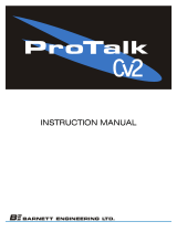
Figure 1 Cv2 Block Diagram
Analog inputs convert the voltage level to a digital value and perform a comparison against
the programmed low and high setpoints. An alarm is present when the measured value is
above or below the setpoint. Alarm messages are spoken using the stored phrase with either
“High” or Low” appended depending on which setpoint has been exceeded. The actual
reading, including decimal place notation and engineering units, is spoken when the Cv2 is
interrogated.
The latching alarm function is also available for analog inputs.
1.3 How are alarms processed?
The way in which the Cv2 processes alarms is shown in Figure 1.

Operations Overview 1-3
B1272M001
BARNETT ENGINEERING LTD. ProTalk Cv2
The hardware input and output ports are activated in the Points section to become part of the
monitoring and control process. There are 30 points which can be referenced to any of the I/O
ports. This allows an analog input to be used by more than one point and monitored for
multiple setpoints, as would be the case where minor and major alarms are required.
If you do not want all of the points to generate the same response when they detect alarms,
they can be placed into different groups. Six groups are available, each with independent
timers and control codes. When a group detects an alarm condition in one of its assigned
points, it executes the sequence of actions found in the current directory. A group can use any
of the six directories to perform the callout function, plus the directory selection can be
changed by using the shift control feature.
1.4 What actions should occur when an alarm is detected?
All alarm conditions will be processed by placing a call on the cellular phone. The called
number and the activities that occur with different alarms are determined by entries in the
directories. A directory contains the sequence of actions that will occur when a group has an
active alarm. Instructions for dialing, speaking, inserting delays and signaling are placed in
the directory in the order in which they are to be performed. There are a total of six
directories; each can contain a unique sequence of activities that will be performed when
alarm conditions exist.
To best describe how a directory controls alarm reporting activities, an example directory
programming session follows. For more information on the directory summary and dialog
box, refer to Chapter 3. The opening window for a directory displays a summary of the
activities that it will perform when an alarm is detected. The directory summary is arranged
as lines; each line represents the sequence of events that will take place during one callout. If
a Dial command is the first entry on the line, the Cv2 will call the programmed number and
then execute the remainder of the commands on that line. After the last command on the line
is competed, the call will be terminated. Commands such as Auto Ack and Wait, when used
as single line commands, do not initiate a call. For a basic sequence where the Cv2 is to call a
phone number and speak the alarm message, the directory line contains the Dial and Voice
commands appearing as:
1. [DIAL]2458829 [VOICE]
This line will cause the Cv2 to place a call to 245-8829 and then speak the Site ID, Group
Name and alarm message, or messages, for all active points. Unless programmed not to, the
Cv2 will append the phrase “Enter Acknowledge Code” at the end of the alarm announcement
and wait for the code to be returned. If the code is received, the alarm sequence will be
terminated until a new alarm occurs. Failure to receive an Acknowledge Code will advance
the sequence of operations to the next line in the directory. If the commands contained in the
last directory line have been completed without reception of an Acknowledge Code, the Cv2
waits for the time interval set in the timers before repeating the process by starting over at
directory line 1.
During execution of the Voice command, the Cv2 will try to announce the alarm messages
three times with a one minute limit for the total announcement duration.

Operations Overview 1-4
B1272M001
BARNETT ENGINEERING LTD. ProTalk Cv2
For example, to call four telephone numbers, the directory would appear as:
1. [DIAL]2458829 [VOICE]
2. [DIAL]2336700 [VOICE]
3. [DIAL]9842121 [VOICE]
4. [DIAL]9843316 [VOICE]
If you want an alert tone to precede the voice message the directory line would look like this:
1. [DIAL]2458829 [ALERT] [VOICE]
The next example shows a sequence that is used to call a numeric paging terminal. After the
call is placed there is a four second delay for the paging terminal to respond before the Cv2
sends the number to be displayed on the pager. When calling a paging terminal, it is
sometimes useful to allow the called party time to call the Cv2 back and acknowledge the
alarm before the Cv2 advances to the next line in the directory. This can be done by using the
Wait command on its own line; the entry below will cause a four minute delay before the next
line is executed.
1. [DIAL]2458829 [WAIT]4 [DTMF]4567
2. [WAIT]240
Directory lines can be added, removed, or modified and new lines can be inserted between
existing lines.
1.5 How do you want to respond to an alarm call?
After the Cv2 has finished speaking the alarm messages, it prompts the called party with the
phrase “Enter Acknowledge Code” and then waits five seconds for the code to be returned. If
the code is received, it will terminate any further callout activities until a new alarm occurs;
otherwise, it will proceed to the next line in the directory. There is a Temporary
Acknowledge Time that can be set in the General section that will override the operation of
the Acknowledge Code. If the temporary time is set to a value other than Off, and the
received Acknowledge Code has the digit # appended to it, the Cv2 will remain in the
acknowledged state only for this time interval. After the timer has expired and if the alarm
condition still exists, the Cv2 will resume alarm reporting. This feature is used as a safety
measure to ensure that an alarm cannot be acknowledged and then left unattended.
Each group has its own Acknowledge Code which only affects points that have been assigned
to the group. Other groups with different Acknowledge Codes will continue alarm reporting
if they do not receive their own code.
Using the Auto Ack command in a directory will cause the Cv2 to automatically acknowledge
any alarms that are in the group using the directory. This feature must also be enabled for that
group, since other groups of points may be using the same directory. Auto Ack must be on
the last line in a directory since any further commands will never be executed.
Another method of acknowledging the Cv2 is by activating the special function that allows
hardware inputs to be used as local acknowledge controls.

Operations Overview 1-5
B1272M001
BARNETT ENGINEERING LTD. ProTalk Cv2
1.6 What if an alarm is not acknowledged?
When the last line in the directory has been completed without receipt of an Acknowledge
Code, a two-stage timer is used to determine when the directory sequence is repeated again.
This timer has two sections: a Short Timer which operates for the number set in Short Cycles,
and a Long Timer which begins after the Short Timer has completed its cycles. This provides
a means of varying the repetition cycle over a period of time.
1.7 What do you want the Cv2 to do when you call it?
In addition to reporting alarms, the Cv2 will also answer incoming calls. This allows you to
interrogate the unit, operate control outputs and change shifts. You can control the level of
security that is presented to incoming calls. With the lowest level, the call will be answered
with the Site ID phrase, the phrases for any groups that have alarms, followed by the prompt
“Enter Command Code”. An Access Code is not required. At the next level of security, the
Cv2 will announce the Site ID phrase and then wait ten seconds for the password code before
allowing access to alarm information or other control functions. At the highest level, the call
is answered but there are no voice prompts; the caller has ten seconds to enter the Access
Code.
Each group of alarms has its own Interrogate Code. When the code is entered, the alarm
status for points in that group is spoken. For digital and watchdog points, the stored phrase
for that point is spoken. Analog points are spoken with the stored phrase and its status -- high,
low or normal -- followed by the reading. For totalizers, the stored phrase is spoken first
followed by the current accumulated value. Interval timers respond with the stored phrase and
the last captured interval.
Control outputs respond with the stored phrase followed by either ‘On’ or ‘Off’ indicating
their current state.
1.8 Sending remote control commands
Points designated as outputs can be controlled using the programmed codes. These codes can
be sent to the Cv2 either during a reporting sequence or when a call is placed to the unit.
During the alarm reporting sequence, the control codes may be sent after the “Enter
Acknowledge Code” prompt is heard. For the next five seconds, the Cv2 will accept
Acknowledge, Interrogate or Control codes. With each received code, the command will be
performed and a prompt for another command entry will then be spoken. For a remote control
output, the status of the output will be spoken after the received code has been executed.
When the unit is called and after the Access Code, if required, has been entered, the prompt to
“Enter Command Code” will be issued.
In either case, the call will be terminated if a valid code is not received during the ten second
window.

Operations Overview 1-6
B1272M001
BARNETT ENGINEERING LTD. ProTalk Cv2
1.9 Indicators
The Cv2 has four LED indicators to show the operation of the unit and assist in troubleshooting.
When the Cv2 is initially powered up, the four LEDs will do the following:
& All will turn on for approximately one second.
& Hook will flash on and off for one second then go out.
& Tone will flash on and off for one second then go out.
& Voice will flash on and off for one second then go out.
& Alarm will flash on and off for one second then go out.
& Hook On power-up, following the initial flashing of each LED, Hook flashes until the
Cv2 has found cellular service. Once the unit has logged onto the cellular
network, the Hook indicator goes out. Hook also flashes while a call is being
placed. After the call has been processed, Hook is on steady until the end of the
call when it goes out.
& Tone Tone blinks once for each DTMF digit that is either received or transmitted.
& Voice Voice is on when the Cv2 is speaking. On power-up, following the initial flashing
of each LED, it will go on continuously for 2 seconds if any section of the stored
database, voice or vocabulary memory is corrupt. If this occurs, the configuration
should be downloaded into the unit and the voice recordings checked for validity.
Voice flashes briefly every second to indicate that the Cv2 is operating correctly.
& Alarm If an unacknowledged alarm is present, the alarm indicator will flash. When the
alarm is acknowledged, Alarm is on steady. When no alarms are present, Alarm
is off.
1.10 Troubleshooting
Is there power to the unit?
When power is first applied to the Cv2, it will flash the Hook indicator until it establishes contact
with the cellular service. At any other time, the presence of power, and correct operation, are
indicated by the brief flashing of the Voice LED every second.
Does the cell phone work?
Use the local call feature to determine if the unit is working properly. If the call cannot be
completed, query the cell phone to see if it responds - any parameter can be used here. Query the
RSSI (Received Signal Strength Indicator) in the phone to see if there is coverage in the area.
The message “error” will be returned if there is no coverage. This can possibly be corrected by
improving the antenna system.

Operations Overview 1-7
B1272M001
BARNETT ENGINEERING LTD. ProTalk Cv2
Are the inputs connected properly?
For digital inputs that are programmed for standard digital operation, create an alarm condition
on the input and confirm that the Alarm LED comes on. Make sure the input is applied long
enough for the debounce to time out. If the Alarm indicator does not come on, the problem is not
necessarily with the input connection. Check that the input is enabled as a valid point, the
associated group is enabled, and the directory is programmed to call out..
For analog inputs, interrogate their group to hear the scaled value at the input.
The unit does not dial out.
Check the Alarm LED to confirm that an alarm is present. If this indicator is not flashing, the
Cv2 will not call out. Check that the input is enabled as a valid point, the associated group is
enabled, and the directory is programmed to call out.
I cannot call into the unit.
If you receive a recording from the telephone company indicating the user is not available, there
may be a problem with the installation or you may be calling the wrong number. Use the
programming phone to confirm the telephone number in the unit.

Installation 2-1
B1272M001 BARNETT ENGINEERING LTD. ProTalk Cv2
Figure 3 Packaged Cv2
2 Installation
The Cv2 can be installed before or after the configuration has been transferred from the PC to the
unit. If the Cv2 is configured in the shop before it is installed in the field, all of the programmed
parameters and voices will remain unchanged in the unit’s non-volatile flash memory.
2.1 Antenna requirements
The antenna used for your installation will depend on the proximity of the alarm unit to the
cellular carrier facility. If the installation is very close to a cell site, a portable style antenna
can be connected directly to the RF connector on the Cv2. If the distance between the
installation and the nearest cell site does not provide adequate signal strength to operate with
the small antenna, then an outdoor or other high gain antenna will be required. Antenna
system details for this type of antenna installation -- antenna type, height and coaxial cable
type -- will depend on the particulars of the site.
If you use the directly connected antenna, it should be oriented vertically.
2.2 Mounting
The Cv2 is available in two versions: the packaged unit which is housed in an enclosure
complete with a battery backed power supply and a programming phone set, or the stand-
alone version which is the Cv2 alarm reporter without the above accessories.
2.2.1 Packaged model
The packaged model should be mounted
onto a wall or other vertical surface in a
location where the temperature cannot
exceed the Cv2 rating.
Before connecting AC power, confirm that
the setting of the voltage range switch on the
power supply module is set for the correct
input, either 110 or 220 VAC.
Connect AC power to the terminal strip on
the power supply module. Connect the
antenna or coaxial feed line to the remote
antenna onto the TNC coaxial jack on the
Cv2.
Connect the input and output signal lines
between the Cv2 and the equipment that you
want to monitor and control. Details of the
input and output ports are discussed later in
this chapter.

Installation 2-2
B1272M001 BARNETT ENGINEERING LTD. ProTalk Cv2
Figure 3 Stand-alone Cv2
Figure 4 Ground Closure Input Wiring
2.2.2 Stand-alone model
The stand-alone Cv2 can be mounted on a flat surface. Make sure that there is enough room
around the unit to make connections. The environment should be clean and dry, with an
ambient temperature that
does not go below -20
o
C
or above +50
o
C.
Connect a DC power
source to the terminals on
TB2. The Cv2 requires up
to 1.5 Amps to operate;
the supply should be sized
accordingly. Input power
to the unit is protected by
a Polyswitch current
limiter. If a fault develops
in the CV2, this switch
will become a high
resistance to prevent damage to the equipment or the power supply. Once this switch has
been activated, the fault must be removed before it will reset and allow current to pass through
to the equipment.
Connect the antenna or coaxial feed line to the remote antenna onto the TNC coaxial jack on
the Cv2.
Connect the input and output signal lines between the Cv2 and the equipment that you want to
monitor and control. Details of the input and output ports are discussed in the next section.
2.3 Input port connections
The input ports can be connected to a variety of contact or voltage sources for monitoring
purposes. Select a wiring configuration that matches your alarm source from one of the
following arrangements:
2.3.1 Ground closure alarm signal
For alarm sources that appear as a ground
closure, either through a mechanical contact
or an open collector driver, the input should
be wired according to Figure 4. If the input
is normally open and goes to ground during
an alarm condition, program the Hardware
section for this input as “Normally High”. If
the reverse is true, set the input to “Normally
Low”.

Installation 2-3
B1272M001 BARNETT ENGINEERING LTD. ProTalk Cv2
Figure 5 +12 Volt Input Wiring
Figure 6 +5 VDC Input Wiring
Figure 8 Analog (unfiltered) Input Wiring
Figure 7 Analog (filtered) Input Wiring
2.3.2 +12 volt alarm signal
The input will accept an alarm signal
that switches between 0 and +12 volts
with the wiring arrangement shown in
Figure 5.
If the signal switches between +12 volts
and an open circuit, as in the case of a
relay contact, the ‘B’ terminal must be
connected to ground to ensure that the
logic level goes to ground when the
voltage is removed.
2.3.3 +5 volt alarm signal
Figure 6 shows how an alarm signal that
switches between +5 volts and ground is
wired. If the alarm signal does not have a
true ground level, terminal ‘B’ must be
connected to ground.
2.3.4 Analog input
For analog signals, either of the wiring configurations shown in Figures 7 and 8 can be used.
The connection shown in Figure 7 will provide additional filtering of the signal.

Installation 2-4
B1272M001 BARNETT ENGINEERING LTD. ProTalk Cv2
Figure 9 Output Wiring
Figure 10 Serial Cable
2.4 Output port connections
The output ports are open collector drivers that can
sink up to 500 mA through a load connected to a
voltage of up to +50 VDC. If an inductive load
such as a relay is connected to an output, install a
protective reverse-biased diode across the load to
prevent damage to the output from the inductive flyback voltage. Figure 9 shows the
connection for an output used as a relay driver.
2.5 Configuration programming connection
When the configuration database is transferred from
the PC to the Cv2, a serial communications cable is
connected between the COM port of the computer and
the serial programming port, J1, on the Cv2. When
the cable is attached to the connector on the Cv2, the
DTR signal is sensed by the Cv2 and it enters the
programming mode. The cable used to connect
between the two pieces of equipment is shown in
Figure 10. To restore the Cv2 to operation, the cable
must be unplugged. The serial programming cable is
supplied with the Cv2.
J1 can also be used to program the cellular radio in
the Cv2. When the Cv2 detects that the serial port is
being used to program the cellular radio, it will
automatically route the communications to the radio.
Figure 11 shows a stand-alone Cv2 installation. The
programming PC is present only when a configuration
database is be transferred to or from the Cv2; the
programming telephone can be either permanently
installed or used only for voice recording. Note that
the phone set can also be used to place outgoing calls,
if required. If the Cv2 is to remain operational during a power outage, the DC power provided
to the unit must be uninterrupted.
Figure 12 shows a packaged Cv2 installation. The programming PC is present only when a
configuration database is be transferred to or from the Cv2; the programming phone is part of
the package and can also be used to place outgoing calls. The built-in power supply contains
an 8 AH battery and is capable of running the Cv2 for at least 12 hours during a power outage.
The power supply has a power fail output signal that can be connected to any of the input ports
on the Cv2 and programmed as an alarm point.

Installation 2-5
B1272M001
BARNETT ENGINEERING LTD. ProTalk Cv2
Figure 11 Stand-alone Cv2
Figure 12 Packaged Cv2

Configuration using the PC 3-1
B1272M001 BARNETT ENGINEERING LTD. ProTalk Cv2
3 Configuration using the PC
This chapter describes how to install the programming software and configure the operation of
the Cv2. When the configuration is complete, it can be viewed through the Summary command
found on the File pull-down menu. In the summary, Warnings should be checked to ensure that
there are no improper settings in the configuration before it is transferred to the Cv2.
3.1 PC requirements
The minimum requirements for the PC used to run the Cv2 programming software are:
• 386 processor
• Windows 95
• 8M RAM
• SVGA screen
• Serial COM port
3.2 Installing the program
The program diskettes supplied with the Cv2 contain the configuration software and the
software installation utility. Place disk 1 into the floppy drive and select the program
SETUP.EXE using Run in the windows Start menu. Follow the instructions and the
installation program will automatically install the configuration program onto the hard drive.
3.3 Starting the configuration program
To start the program, click on the Cv2 icon that appears in the installed location. The program
will load and search for the default startup files:
Cv2.dat - the configuration database
Cv2.cfg - the serial port setting
If these files are not found, default files will be created and a warning posted.
3.4 The desktop and how to access programming functions
At the top of the desktop are drop-down menus and buttons on the taskbar that launch the
various operations in the program. The taskbar buttons duplicate the operations found in the
menu. To activate on-line help, press F1 or select the Help menu at the top of the desktop.
Context help for the controls is available when dialog boxes are open. Press the Help
question mark in the upper right of the dialog box, place the curser with the question mark
over the control, then click the left mouse button.
The menu and button operations are summarized in the following section.

Configuration using the PC 3-2
B1272M001 BARNETT ENGINEERING LTD. ProTalk Cv2
3.4.1 File Operations
File Open
If you do not want to edit the default database, use the File Open button to select a different
configuration file. This will bring up the standard Windows File Open dialog box where you
can open another .dat file.
File Save As
To save the current configuration under a different name, use the Save As button to bring up
the standard Windows Save As dialog box. Enter a new name and save the file. After the file
has been saved under a different name, subsequent save operations will store the configuration
data with the new name.
File Save
Use the Save button to save the current configuration database. If the name has not been
changed during this session using Save As, the data will be stored as the default Cv2.dat file.
If the name has been changed then the file will be saved under the new name.
3.4.2 Hardware
Inputs
This section is used to set the type of input for each port and select basic hardware settings.
Outputs
This section is used to set the type of output for each port and select basic hardware settings.
3.4.3 General
Settings that concern the operation of the entire Cv2 are entered in the General section.
3.4.4 Groups
Each of the six groups can be set to provide different alarm reporting operations for
selected points.
3.4.5 Points
In the points section, any of the hardware inputs and outputs can be selected for the Cv2
to use as alarm reporting or remote control functions. There are 30 points available.

Configuration using the PC 3-3
B1272M001 BARNETT ENGINEERING LTD. ProTalk Cv2
3.4.6 Directories
When an alarm is detected, the Cv2 will perform a specific sequence of events
determined by the entries in the directory. Six directories are available, providing
different actions for different groups.
3.4.7 Programming
The programming section is used to transfer the configuration database between the PC
and the Cv2. Recorded voices can also be transferred from the Cv2 and then back.
3.5 Configuring the Cv2
When configuring the Cv2, the sequence described in the following section is the simplest
way to get the unit operational. If the Cv2 uses any of the special port functions -- Alarm
Active, New Alarm, Acknowledge Received, Local Acknowledge or the Totalizer Reset
Input -- you must consider the relationship between these functions and the Hardware, Groups
and Points sections when configuring the unit.
3.5.1 Hardware section
Start with the Hardware section to establish settings for the input and output ports. Input ports
can be configured as Digital, Analog, Watchdog, Totalizer or Interval types. Each port can be
independently set to one of these types; an individual port can have only one type assigned.
Output ports can be either On/Off or Timed types.
To select an input for configuration click on the Hardware Inputs button to bring up the
summary of the input settings. Each of the eight inputs will be shown along with its current
type and hardware settings. The input to be edited is highlighted and can be selected by
pressing Enter, double-clicking on the line, or selecting the Edit Line function from the
menubar. Selecting an input for editing will produce the dialog box for that input type.
After an input or output port has been configured, it can be activated in the Points section for
alarm reporting, monitoring or control purposes. Input ports can be changed to one of the
other types by selecting from the Change Input Port drop-down list. Changing the input type
will force any variables used in the Hardware section to the default value and will remove any
points that make use of this port. Output ports can be changed from one type to the other.
Digital Input
A Digital input represents the basic input type, responding to either high or low signals to
indicate the status of the port. Wiring of the port determines if ground closure or voltage
signals are being monitored.
Debounce times are set to qualify the state of the input before it is considered valid. Two
debounce time ranges, seconds and minutes, are available. The seconds range has a
maximum value of 1638 seconds (27 minutes) with a resolution of 25 msec. For longer
debounce times the minutes range should be used. When set to minutes, the debounce
timer has a maximum value of 65,535 minutes with a resolution of one minute. For short

Configuration using the PC 3-4
B1272M001 BARNETT ENGINEERING LTD. ProTalk Cv2
debounce times, use the seconds timer to avoid the inaccuracy introduced by the one
minute resolution.
Default Debounce time: 0.05 sec
A Digital input port can also be used to perform special functions in the Cv2. In the
Groups section, it can be selected for the Local Acknowledge function, and in the
Hardware section it can be set to operate as a Reset Input for a Totalizer.
Watchdog Input
A Watchdog timer is used to monitor periodic events and will produce an alarm if the
event does not occur within the programmed Watchdog interval. Each time an event
occurs at the input, the timer is reloaded with the programmed value. When the timer has
expired without a refresh event, the alarm is set. Refresh activities can be changes from
low to high, changes from high to low, or both.
Watchdog input types use two timers for their operation: the Debounce timer and the
Watchdog Interval timer. Refer to the preceding Digital input description for details on the
Debounce timer. Two Watchdog time ranges, seconds and minutes, are available. The
seconds range has a maximum value of 1638 seconds (27 minutes) with a resolution of
25 msec. For longer Watchdog times the minutes range should be used. When set to
minutes, the Watchdog timer has a maximum value of 65,535 minutes with a resolution of
one minute. For short Watchdog times, use the seconds timer to avoid the inaccuracy
introduced by the one minute resolution. When setting the two timers, take into
consideration the relationship between the two. The Debounce time can not be greater than
the Watchdog Interval; otherwise a constant alarm condition will occur.
Default Watchdog time: 10 min
Interval Input
Interval timers measure the time interval that an input is active, either how long it is high or
how long it is low. The input is conditioned by the Debounce timer which is described in
the Digital input section. When setting the Debounce timer, consider the anticipated
duration of the interval. Since the Cv2 registers a change only after the Debounce time,
long debounce settings will affect the accuracy of the measurement.
Totalizer Input
Totalizer inputs measure the number of times that an event has occurred at the input. The
event can be a high to low transition, a low to high transition, or both. Before the change is
considered valid, it is conditioned by the Debounce timer - described in the Digital input
section. Take into consideration the expected time period between events when setting the
Debounce timer.
The count in the totalizer can be reset by two methods: by sending the Reset Code entered
in the Points section, or by using the Reset Input selection in the Hardware setup.

Configuration using the PC 3-5
B1272M001 BARNETT ENGINEERING LTD. ProTalk Cv2
Analog Input
Setting the input port type to Analog allows measurement of voltages between 0 and
+5 volts. As with the other input types, the definition of an analog input is completed in
the Points section where the range, setpoints and units are assigned.
An Analog port can be changed to one of the other input types by selecting from the
Change Input Port drop-down list. Changing input type will force any variables used in the
Hardware section to the default value and will remove any points that make use of this
input.
On/Off Output
On/Off outputs operate with two DTMF codes that are set in the Points section. One code
turns the output On and the other returns it to the Off state. The output will remain in the
last commanded state indefinitely.
To make an On/Off port operational for remote control or as one of the special functions --
Alarm Active or New Alarm -- it must be configured and enabled in the Points section.
Timed Output
Timed outputs are activated by receipt of a single DTMF ‘On’ code. This code is set in the
Points section. When the code is received, the output will activate and will remain in that
state until the timer expires or the DTMF ‘Off’ code is received.
Two timer ranges, seconds and minutes, are available. The seconds range has a maximum
value of 1638 seconds (27 minutes) with a resolution of 25 msec. For longer times the
minutes range should be used. When set to minutes, the timer has a maximum value of
65,535 minutes with a resolution of one minute. For short times use the seconds timer to
avoid the inaccuracy introduced by the one minute resolution.
When the command to turn on the Timed output has been received and executed, the Cv2
will announce the current state of the output port. If the timer value is set to a short
interval, it is possible that the output will have returned to the Off state by the time the
status is announced.
To make a Timed port operational for remote control or as one of the special functions --
Alarm Active, New Alarm or Acknowledge Received - it must be configured and enabled
in the Points section.
3.5.2 Points section
After the Hardware ports are configured, use the Points section to specify how activities on
these ports are processed. There are 30 points available for use as either input or output
controls. It is in the Points section that inputs are given the ability to generate alarms and
outputs are enabled to perform remote control functions. Each point can be referenced to any
of the input or output ports. When a port is selected in Points it will have the characteristics
that were set in the Hardware section. If a different type of operation is required for a port, it
must be changed in the Hardware section.

Configuration using the PC 3-6
B1272M001 BARNETT ENGINEERING LTD. ProTalk Cv2
Each point can be placed into one of the six groups. If a port is used for one of the special
functions, the Group section sets the ports.
To access a point for configuration, select the Points button to bring up the summary of the
settings. Status of the 30 points will be shown along with a brief description of their settings.
Highlight the point to be edited, then select it by pressing Enter, double-clicking on the line,
or choosing the Edit Line function from the menubar. Selecting a point will bring up the
dialog box for that type.
Depending on the type of point, the contents of the dialog box will vary. There are a number
of common settings that appear in all of the point dialog boxes:
Common Settings for Points
I/O Port Selection
If you would like to change the type of input or output, select one of the other available
ports. Changing the port will force the point to its default settings and the settings for
the current point will be lost.
If a port is being used for one of the special functions, an abbreviated Function Code
will also be displayed in the port selection list:
>ACK< Local acknowledge input for one or more groups.
>RES< Reset input for one or more totalizers.
<ALM> Output used to indicate there is an Alarm Active in one or more groups.
<NEW> Output used to indicate that there is an unacknowledged, or New Alarm,
in one or more groups.
<ACK> Output used to indicate that an Acknowledge Code has been received for
one or more groups.
Default Port Selection: Unused, not included in any reporting activities.
Point Name
The Point Name is a 16-character text field where you can enter a description of the
point. This name is used for quick identification in the point summary; otherwise it is
not required for operation of the Cv2. Normally the name assigned is the same as the
voice message programmed into the Cv2 for this point.
Default Point name: empty text string.
Using Group
Each point is placed into a group, which will determine, through a directory, what
actions take place when an alarm occurs. For example, groups could be set up to
process alarms specific to security, maintenance and/or operations. Points would then
be assigned to the group concerned.
Default group: Group 1.
/